


215T-Trailer-ISM-RevC-06-06-18
Page 1
ENG
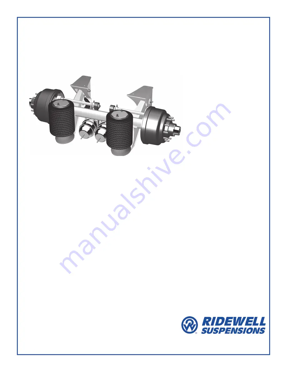
RCA-215T - Trailer
Nonsteerable – Auxiliary Axle Suspension
Installation and Service Manual
Suspension Identification ..................................... 2
Suspension System Serial Tag
Installation ............................................................. 3
Prior to Installation
Axle Integration
Axle Weld Standards
Suspension Mounting
Air Control Kit - Troubleshooting
Maintenance .......................................................... 9
Recommended Service Intervals
Parts Illustration
215T Trailer Suspension
Bushing Replacement Kit
Bushing Replacement Procedure
Appendix .............................................................. 14
Torque Specifications
Axle Alignment
Warranty ............................................................... 16
Part No.:
9710113
Doc.:
215T-Trailer-ISM-RevC-06-06-18


