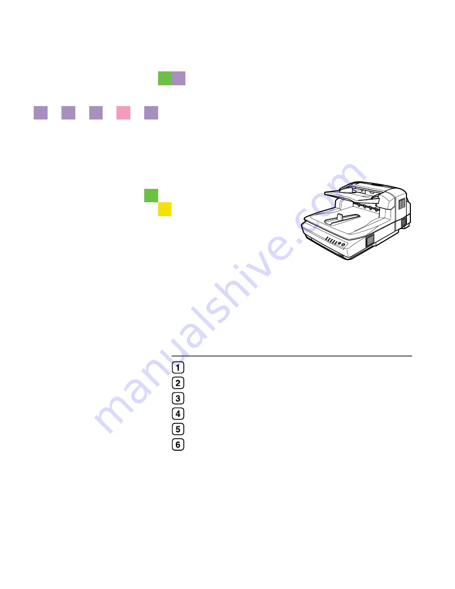
background image

Image Scanner

Operating Instructions

Read this manual carefully before you use this machine and keep it handy for future reference. For safe and correct use, be sure to read the Safety
Information in this manual before using the machine.

Guide to Components

Setting up the Scanner

Installing Software

Setting Originals

Using the TWAIN Driver

Appendix

Summary of Contents for IS760

Page 1: ...use this machine and keep it handy for future reference For safe and correct use be sure to read the Safety Information in this manual before using the machine Guide to Components Setting up the Scan...

Page 2: ...inting cer tain items consult with your legal advisor Power Source Color Scanner 120V 60Hz 10A or more Please be sure to connect the power cord to a power source as above Trademarks Adobe PostScript a...

Page 3: ...Automatically 23 Connecting the SCSI Cable When the Scanner is at the End of the Daisy Chain 24 Connecting the SCSI Cable When the Scanner is not at the End of the Daisy Chain 26 Using the Scanner on...

Page 4: ...ginal is Jammed or Double Fed in the ADF 64 When the Originals are Not Fed Correctly 66 When Scanning is Not Performed as Expected 66 When an Error Message Appears 67 When in Installation and Other Pr...

Page 5: ...manual the following important symbols are used R WARNING Indicates a potentially hazardous situation which if instructions are not followed could result in death or serious injury R CAUTION Indicate...

Page 6: ...sure the wall outlet is near the machine and easily accessible so that in event of an emergency it can be unplugged easily Do not use with a power source with a voltage different from the specified v...

Page 7: ...d to meet high standards of quality and functionality and we recommend that you only use the expendable supplies available at an authorized dealer Keep the machine away from humidity and dust A fire o...

Page 8: ...Original Table Specifications As an ENERGY STAR Partner we have determined that this machine model meets the ENERGY STAR Guidelines for energy efficiency The ENERGY STAR Guidelines intend to establish...

Page 9: ...operation of this scanner all users should read and follow the instructions carefully Quick Installation Guide Describes how to install the scanner Operating Instructions this manual Provides all of t...

Page 10: ...to read the instructions all of which are described in the Safety Information section The statements above are notes for your safety Important If this instruction is not followed paper might be misfe...

Page 11: ...able The originals that have been loaded by the ADF are output here after scanning 5 Original Stopper Stops the originals scanned by the ADF 6 Rotary Switch Use to set SCSI ID 7 DIP Switches Use to se...

Page 12: ...ing 5 ADF Cover Open when clearing the misfed originals or cleaning the rollers 6 Lock Screw This is to lock the scanning parts inside when you transport this machine Re move this screw when you set u...

Page 13: ...l indicators blinking System error Contact your service representative Description of the Error indicator on See p 63 Error Indicators Indicators On Blink Off Status of Power Power On Low Power mode P...

Page 14: ...nnection cannot be used when the SCSI synchronous transmission is set You can turn the DIP Switch No 2 OFF SCSI synchronous transmission enabled when using the scanner only with the SCSI connection A...

Page 15: ...and the other of this ma chine compared to a level surface Space Make sure that the scanner is in a location where there is enough space to pro vide the clearance as illustrated below and also provide...

Page 16: ...vision set In a location subject to extreme temperatures or humidity Near a humidifier Set up the scanner in a location where the temperature and humidity will fall within the ranges shown below Impor...

Page 17: ...screws fixed on the back of this machine Note Use a coin to remove the lock screws Be sure to remove the lock screws Turning the power on without remov ing the screws could result not only in failure...

Page 18: ...ith the Velcro B The removed screws are to be kept fixing on the back of the Pressure Panel C Return the removed Background Panel to where it was Reference Regarding how to set the Background Panel pl...

Page 19: ...e the Setup 15 2 Note Be sure to set the lock lever to the Unlock position Turning the power on leaving the lock lever to the Lock position could result not only in fail ure in scanning but in malfunc...

Page 20: ...l to remove or fix the screws A A A A Turn OFF the power to this product and disconnect all cables connected to the product including the power cable B B B B Remove the three screws on the lower back...

Page 21: ...unit and fix with one accessory screw G G G G Check that it is connected tightly check that there are no foreign objects such as metal on the scanner control unit H H H H Close the scanner control uni...

Page 22: ...ote The optional IEEE 1394 interface board is alternatively used with the USB in terface board A A A A Turn OFF the power to this product and disconnect all cables connected to the product including t...

Page 23: ...s 19 2 D D D D Remove the seven screws on the cover of the scanner control unit E E E E Open the cover of the scanner control unit F F F F Remove the USB 2 0 interface board fixed with 6 screws ADC064...

Page 24: ...oreign objects such as metal on the scanner control unit I I I I Close the scanner control unit cover and fix with seven screws then insert the scanner control unit into the main unit Note Be sure to...

Page 25: ...of the computers About the SCSI Interface Connection of this scanner to the SCSI Small Computer System Interface is as follows This scanner is compliant for SCSI 3 You can daisy chain with SCSI 1 2 c...

Page 26: ...e Push the knob of the cover to the left and pull the cover to open B B B B Confirm the DIP Switch No 1 to the OFF position SCAM function is disabled C C C C Set the SCSI ID by rotating the Rotary Swi...

Page 27: ...SI ID is overlap ping with the other SCSI device set the SCSI ID manually A A A A Open the cover of the switch box on the lower left of the frontside of the scanner Note Push the knob of the cover to...

Page 28: ...in the computer scanner and SCSI connected devices Note Connect the SCSI cable to either one side of the connectors C C C C Open the cover of the switch box on the lower left of the frontside of the s...

Page 29: ...Connecting to the Computer 25 2 Note Press the Hard Reset Switch if you changed the SCSI ID while the power is ON p 34 Using the Hard Reset Switch...

Page 30: ...connected devices B B B B Daisy chain the computer scanner and SCSI connected devices C C C C Open the cover of the switch box on the lower left of the frontside of the scanner Note Push the knob of t...

Page 31: ...scan time The USB and the optional IEEE1394 connection cannot be used when the SCSI synchronous transmission is set A A A A Open the cover of the switch box on the lower left of the frontside of the...

Page 32: ...e time from two computers Interfaces are switched au tomatically when you change from one of the computer to the other A A A A Open the cover of the switch box on the lower left of the frontside of th...

Page 33: ...of some PC Please use the recommended IEEE1394 interface board for your PC As for the recommended boards please ask you service representative You can connect the scanner to three computers at the sam...

Page 34: ...eset Switch if you changed the DIP Switch while the pow er is ON p 34 Using the Hard Reset Switch C C C C Connect the IEEE1394 cable to the IEEE1394 connector Note Connect the cable to either one of t...

Page 35: ...specified voltage Do not use a power outlet with multiple devices plugged in These could create the risk of fire or electric shock Avoid the use of an extension cord Do not damage break twist or modi...

Page 36: ...n the back of the machine is set to the Unlock position Important Be sure to set the lock lever to Unlock Turning on the power with the lock lever set to Lock could result in failure in scanning or in...

Page 37: ...On Turning the Power On when Connected with SCSI Interface Turn the power on from the farthest devices from the computer on the daisy chain Start the computer last Note The scanner will not be detect...

Page 38: ...ou can turn off the scanner and turn it on again or follow the procedures below A A A A Open the cover of the switch box on the lower left of the frontside of the scanner Note Push the knob of the cov...

Page 39: ...ning the power of the scanner OFF System Requirements Install TWAIN Driver to the computer that meets the system requirements be low A recommended environment is for scanning documents by 16 770K Full...

Page 40: ...r Driver s Utilities and Operating Instructions into the CD ROM drive of the client computer The CD ROM Launcher screen appears When installation does not start automatically Auto Run might not automa...

Page 41: ...ue the installation by clicking Continue About TWAIN driver help After you have installed the TWAIN driver Model Name TWAIN V4 will be cre ated under Programs of the Start menu Help files for the TWAI...

Page 42: ...em Requirements Install DeskTopBinder Lite to the computer that meets the system requirements below Hardware PC AT compatible CPU Pentium 133 MHz or faster Pentium II 266 MHz or faster recommended Mem...

Page 43: ...he CD ROM Launcher screen appears When installation does not start automatically Auto Run might not automatically work with certain operating system set tings A Launch Setup exe located in the CD ROM...

Page 44: ...ation Start installation retaining the power of the scanner OFF System Requirements Install ISIS Driver to the computer that meets the system requirements below Hardware PC AT compatible Display Resol...

Page 45: ...ner Driver s Utilities and Operating Instructions into the CD ROM drive of the client computer The CD ROM Launcher screen appears When installation does not start automatically Auto Run might not auto...

Page 46: ...he course of the installation follow the instruction accordingly Even when No approval of the logo test appears on the display you can continue the installation by clicking Continue Changing the conne...

Page 47: ...ion Log on to the computer as a member of the Administrators group for instal lation to Windows 2000 XP or Windows Server 2003 A A A A Start Windows and then insert the supplied CD ROM labeled Scanner...

Page 48: ...Installing Software 44 3...

Page 49: ...ck side It may not be possible to scan a full color original even if it meets require ments of the chart above See Readme txt in the CD ROM for details Where original is set Original size Main scannin...

Page 50: ...n set on the Exposure glass Unable to detect automatically When set on the ADF 11 17 279mm 432mm R 8 1 2 14 Legal 216mm 356mm R 8 1 2 13 216mm 330mm R 8 1 2 11 Letter 216mm 279mm R 8 1 2 11 Letter 279...

Page 51: ...the ADF Placing the following types of originals in the ADF can cause paper misfeeds or result in damage to the originals Place these originals on the exposure glass instead Stapled or clipped origina...

Page 52: ...F A A A A Lift the Pressure Panel B B B B With the side to be scanned facing down place the original on the exposure glass and align it with the home position and scale 1 Home position 2 Scale Importa...

Page 53: ...excess of the upper limit mark In case the end of originals are curled too much to feed with the ADF de crease the number of originals or adjust the curled end of originals straight See p 46 Original...

Page 54: ...hold the stopper to open the ADF B B B B Align the originals To have the originals scanned in order set the originals in order illustrated below Simplex scanning Duplex scanning C C C C Fan the origin...

Page 55: ...ng the root part of the original guide located over the original tray ditch Be careful not to drop any alien objects such as paper clip dust etc into the original tray ditch Check that the ADF is clos...

Page 56: ...s that can be automatically detected will be different depending on the color of the Background Panel p 46 Original Sizes Available for Auto Detection You can reduce the transparencies of the duplex p...

Page 57: ...ground Pan el by rotating the screw on the right to the mark position Note Turn the slit in the way shown in the illustration Do not turn to the other side Turn the slit till you hear the click Rotate...

Page 58: ...el for the Exposure Glass reverse the panel A A A A Lift the Pressure Panel and carefully pull out the Background panel that is fixed with magic tapes B B B B Place the Background Panel on the Exposur...

Page 59: ...ght of the Background Panel with the home position for originals 1 Home position D D D D Close the Pressure Panel slowly and press it down firmly E E E E Lift the Pressure Panel again and press all ov...

Page 60: ...Setting Originals 56 4...

Page 61: ...u may be different depending on the application you use Scanning Originals A Select and start the TWAIN driver Menu may be different depending on the application you use Scanning Originals B F Place t...

Page 62: ...of the scanner you installed with the TWAIN driver will be dis played in the Source list D D D D Select the model name and then click Select The TWAIN driver for the scanner is selected and the Sourc...

Page 63: ...ll close Note With DeskTopBinder Lite it is possible to edit and print scan files For more information about how to edit and print see DeskTopBinder Lite Help J J J J Save the scanned image in DeskTop...

Page 64: ...e No combination or di vision You can divide two page spread originals to two individual page images or combine duplex printed originals to a simplex one page image 256 Colors in Col Grad Reduces 24bi...

Page 65: ...ill be automati cally detected for both ADF and Exposure Glass by the Auto detect Mixed size function Double Feed Detect Ultrasonic Wave Length Ultrasonic Wave Length Off While using ADF it detects an...

Page 66: ...Using the TWAIN Driver 62 5...

Page 67: ...he same status note the status of the indicators and contact your service representa tive Error description Solution The ADF or ADF cover is not fully closed Close the ADF or ADF cover An original is...

Page 68: ...e original by the following procedure A A A A Open the ADF cover and remove if the original is jammed B B B B Remove the original if it is jammed in the cove of the Original Table Note You can easily...

Page 69: ...g the Color of the Background Panel for the Exposure Glass B Turn down blue levers on both sides The unit which stores the Background Panel for the ADF is drawn out C Remove the jammed original Note R...

Page 70: ...re Glass Background panel Feed roller or Original Roller is dirty Clean the Exposure Glass the ADF Expo sure Glass Background panel Feed roller or Original Roller p 71 Cleaning The originals are damag...

Page 71: ...uired Action Cannot find the scanner Check if the scanner main pow er is on The TWAIN driver cannot find the scan ner When using SCSI you have the computer started before turning on the scanner It is...

Page 72: ...n ADF The misfed original is jammed inside the ADF Remove the misfed originals and scan again p 64 When the Orig inal is Jammed or Double Fed in the ADF Remove the misfed originals and clear the error...

Page 73: ...press Yes to contin ue No to end Double Feed More than 2 sheets of origi nal was fed into the ADF at once has oc curred and was de tected To continue scanning replace the double fed originals to the...

Page 74: ...ling Software for details The computer cannot de tect the scanner when they are connected by USB or IEEE1394 SCSI synchronous transmission is en abled Set the DIP Switch No 2 to the ON po sition Then...

Page 75: ...nd then remove moisture thoroughly with dry cloth Important Do not use volatile chemicals such as benzene paint thinner or spray with in secticides This can cause deformation discoloration and crackin...

Page 76: ...all around the Feed Roller with a tightly wrung cloth by turning the roller with your fingers 1 Feed Roller Note Always make sure to clean the Feed Roller after scanning a document writ ten in pencil...

Page 77: ...t let B B B B Lift the Pressure Panel C C C C Wipe the Background Panel the ADF Exposure Glass 1 and the Exposure Glass with the cleaning cloth or a dry and soft cloth taking a good care of the magic...

Page 78: ...simplex model A A A A Turn off the power of the scanner and unplug the power cord from the out let B B B B Lift the Pressure Panel C C C C Take off the Background Panel Reference p 54 Changing the Co...

Page 79: ...y wrung cloth 1 Rollers Reference Regarding how to set back the store box for the ADF Background Panel please refer to the step E of p 52 Changing the Color of the Background Panel for the ADF Regardi...

Page 80: ...the ADF C C C C Wipe the rollers with a tightly wrung cloth by turning them with your fin gers 1 Rollers D D D D Wipe the rollers in the cove with a tightly wrung cloth by turning them with your finge...

Page 81: ...nel in every six months However please clean it properly when it gets dirty A A A A Turn off the power of the scanner and unplug the power cord from the out let B B B B Open the ventilation cover pane...

Page 82: ...r packaging and transport are to be per formed by the customer Moving Over Short Distances A A A A Turn off the power of the scanner and unplug the power cord from the out let B B B B Disconnect all c...

Page 83: ...turn it off B B B B Set the Lock Lever on the left side of the scanner to the Lock position C C C C Fix it with the two lock screws kept on the back of the Pressure Panel A Lift the Pressure Panel an...

Page 84: ...caps are to be kept in a bag and transported together with the machine since they are used at the place where the machine is set up E Fix tightly with the lock screws Note Use a coin to tightly fix th...

Page 85: ...Disposing of the Scanner 81 6 Disposing of the Scanner When you want to dispose of your scanner contact your dealer or a service rep resentative...

Page 86: ...nnot per form a scanning operation with the relevant settings due to the limitation of the TWAIN compliant application you use for scanning For information about the maximum data size that the applica...

Page 87: ...26 15 054 11 17 1 826 7 304 16 435 29 218 81 2 14 1 162 4 648 10 458 18 593 29 052 81 2 13 1 079 4 316 9 711 17 265 26 977 81 2 11 913 3 652 8 217 14 609 22 827 51 2 81 2 456 1 826 4 108 7 304 11 413...

Page 88: ...54 B5 2 123 8 495 19 113 33 982 53 100 76 460 A5 1 411 5 645 12 701 22 581 35 283 50 807 69 154 90 324 B6 1 057 4 230 9 519 16 925 26 446 38 079 51 832 67 701 A6 705 2 822 6 350 11 289 17 639 25 401 3...

Page 89: ...consisting of both texts and photos You can set the photo part alone as the para intermediate gray tone For an orig inal mainly occupied by photos to the contrary you can detect and scan the original...

Page 90: ...m Max 0 4 inch 10 mm Min Sub direction 17 inch 432 mm Max 0 4 inch 10 mm Min Optical resolution Main scanning 400 dpi Sub scanning 400 dpi Scanning grade Input 10 bits per pixel for each color Output...

Page 91: ...consumption During operation 180 W During standby 50 W During Low Power mode 8 W Warm up time Max 20 seconds Transition time to the Low Power mode Recovery time from the Low Power mode Transaction ti...

Page 92: ...Clear Modes key 7 Connecting Computer 21 IEEE1394 29 IEEE1394 Board 18 Image Processing Unit 16 Options 16 Power Code 31 SCSI 21 USB 28 D Data Size 82 DeskTopBinder Lite Installation 38 DIP Switches...

Page 93: ...tallation 43 R Resolution and Data Size 82 Rotary Switch 7 S Scan Area and Data Size 82 SCSI ID Setting Automatically 23 Setting Manually 22 SCSI Interface Connector 8 SD Card Slot 8 Setting Originals...

Page 94: ...90 EN USA G418 8602 MEMO...

Page 95: ...In accordance with IEC 60417 this machine uses the following symbols for the main power switch a a a a means POWER ON b b b b means POWER OFF Copyright 2004...

Page 96: ...Image Scanner Operating Instructions EN USA G418 8602...

Reviews: