manualshive.com logo in svg
background image

Original  Instruction  Manual
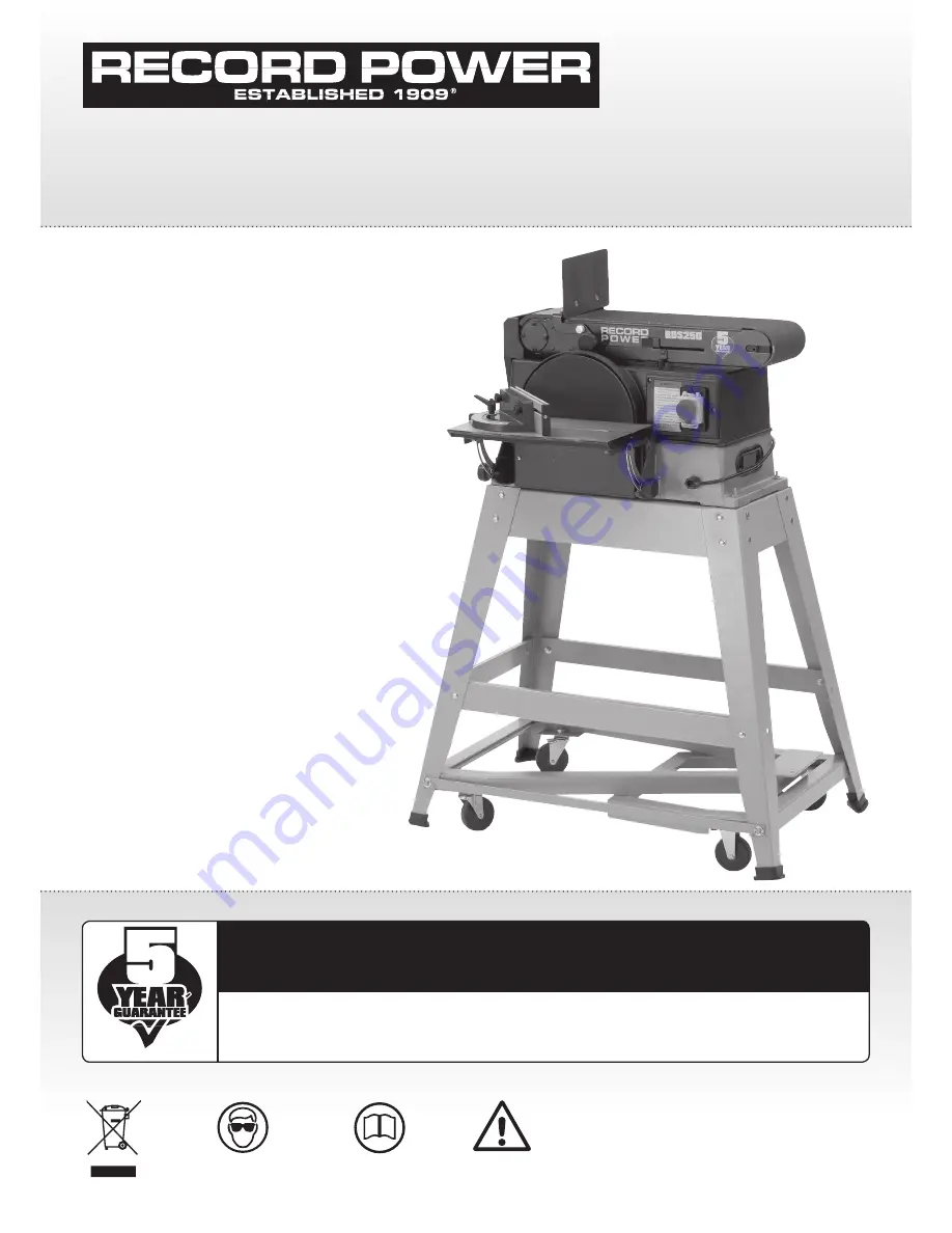
BDS250

 10" x 6" 

Belt & Disc Sander

Always wear safety glasses when 
using woodworking equipment.

Always read the instructions 
provided before using 
woodworking equipment.

i

Kg

Version 3.0

January 2013

Show with optional stand and wheel kit.

To register this product please visit

www.recordpower.info

It is important to register your product as soon as possible in order to receive efficient after sales 

support and be entitled to the full 

5 year guarantee

. Your statutory rights are not affected. 

Please see back cover for contact details.

Important

For your safety read instructions carefully 
before assembling or using this product.
Save this manual for future reference.

i

Kg

Содержание BDS250

Страница 1: ...d and wheel kit To register this product please visit www recordpower info It is important to register your product as soon as possible in order to receive efficient after sales support and be entitled to the full 5 year guarantee Your statutory rights are not affected Please see back cover for contact details Important For your safety read instructions carefully before assembling or using this pr...

Страница 2: ...g Checking Contents 7 Assembly Instructions 8 Getting to Know your Belt Disc Sander 9 No Volt Switch 10 Basic Operation 11 Maintenance 12 Troubleshooting 13 Dust Extraction 14 Electrical Connection Wiring Diagram 15 Exploded Diagram Parts List 16 Assembly of the Optional BDS250 A Stand 17 Assembly of the Optional BDS250 W Wheel Kit EU Declaration of Conformity Contents ...

Страница 3: ... or blades Gloves should NOT be worn when using the machine as they can be caught in moving parts of the machine Non slip safety footwear is recommended when using the machine and handling large work pieces 2 Dress appropriately Do not wear loose clothing neckties or jewellery they can be caught in moving parts of the machine Roll up long sleeves above the elbow Wear protective hair covering to co...

Страница 4: ...allows your body to remain balanced and feed the work piece in to the machine without overreaching Keep proper footing and balance at all times 15 Electrical supply Electrical circuits should be dedicated to each machine or large enough to handle combined motor amp loads Power outlets should be located near each machine so that power or extension cables are not obstructing high traffic areas Obser...

Страница 5: ...section of the manual for details of the specific dust extraction requirements for this machine The dust extractor should be switched ON before starting the machine that it is connected to The dust extractor should be left running for 30 seconds after the last machining operation is complete in order to clear any residual waste from the machine 26 Ensure that the machine is correctly guarded Never...

Страница 6: ...im under this guarantee proof of the original purchase date will be required to validate the warranty period 2 Claims Procedure 2 1 In the first instance please contact the Authorised Dealer who supplied the Product to you In our experience many initial problems with machines that are thought to be due to faulty parts are actually solved by correct setting up or adjustment of the machines A good A...

Страница 7: ...arning For your own safety never connect plug to power source outlet or switch on until all assembly steps are complete and until you have read and understood the entire Owner s manual For assembly you will need not included Standard Screwdriver Phillips Screwdriver 10 mm wrench Item Description Quantity A Belt disc sander assembly 1 B Owner s manual 1 C Table 1 D Sanding disc 1 E Mount support ta...

Страница 8: ...movement the supporting surface where the belt and disc sander is mounted should be examined carefully after mounting to ensure that no movement during use can result If any movement occurs secure the workbench or supporting surface before resuming operation of the belt and disc sander Installing Sander Disc and Guard 1 Remove the backing from the self adhesive sanding disc Align perimeter of disc...

Страница 9: ...ng the work or fingers between the table and sanding surface the table edge should be a maximum of 3 mm from sanding surface 7 Loosen the 4 M6 hex nuts under the table 8 Using a suitable spacer for example a 3 mm thick piece of card or 3 mm diameter drill bit hold the table against the spacer and tighten the 4 M6 hex nuts Fig 7 6 Squaring Table Assembly Warning To avoid injury from accidental star...

Страница 10: ...ever to the left to release the belt tension Fig 7 12 6 Place the sanding belt over the drums with the direction arrow pointing as shown in Fig 7 13 Make sure the belt is centred on both drums 7 Slide tension lever to the right to apply belt tension Fig 7 12 8 Tighten hex socket screw when bed is in desired position 9 Reinstall the work support 10 Rotate the belt by hand in the direction of the ar...

Страница 11: ...he left applies belt tension 5 Work support hex screw 6 Work support Supports the workpiece on the sanding belt 7 Base 8 Belt bed 9 Mounting holes 10 No volt switch 11 Sanding Disc 12 Sanding paper 13 Work table assembly 9 No Volt Switch Note The no volt switch has no volt release and emergency stop feature This feature is intended to prevent the unauthorised starting 1 To turn machine on raise th...

Страница 12: ...t the side coming up from under the table could damage the work by making it chatter or tear the work from your hands and throw it In the Event of a Blockage or if the Machine Stalls If the machine stalls due to the work piece or sanding belt becoming trapped switch the machine of immediately by pressing the red button on the switch marked O Locate and rectify the source of the blockage If the san...

Страница 13: ...cket head locking screw Surface Sanding On The Belt Warning To avoid injury from slips jams or thrown pieces adjust the work support to clear the sanding surface by no more than 3 mm When checking clearance between the belt and work support press the belt flat against the metal beneath it Hold the workpiece firmly with both hands keeping fingers away from the sanding belt Fig 10 5 Keep the end but...

Страница 14: ...side of the disc can cause workpiece to fly up kickback and result in injury Sanding Small End Surfaces on the Sanding Disc Note Use of a mitre fence is recommended for this operation Always move the work across the left side of centre on the sanding disc face as shown Fig 10 8 Warning For your own safety remove the plug from power source outlet before adjusting the sander Use a combination square...

Страница 15: ...wrench to tighten tension between pulleys Fig 11 2 5 Tighten 4 M8 hex head screws careful 6 Test belt tension by placing fingers on either side of the belt and squeeze There should be about a 6mm give on the belt Fig 11 3 Please note Excessive tension on the pulley belt may cause increased noise and overload the motor Excessive movement on pulley belt may cause the belt to fail prematurely 7 Locat...

Страница 16: ...tor is switched off for 20 minutes then the other can be used thus enabling continuous usage Or both motors can be used simultaneously giving maximum suction but in this mode the extractor must be switched off for 20 minutes every hour 0 5 micron filtration DX5000 High Filtration Dust Extractor Bag type extractor 200 litre capacity Twin 1 kW motor suitable for heavy usage ie if one motor is switch...

Страница 17: ...63 plug for use in the UK always ensure that it is fitted with a fuse conforming to BS1362 appropriate to the rating of the machine If replacing the original fuse always fit a fuse of equivalent rating to the original Never fit a fuse of a higher rating than the original Never modify the fuse or fuse holder to accept fuses of a different type or size Where the current rating of the machine exceeds...

Страница 18: ...18 15 Exploded Diagram Parts List ...

Страница 19: ...llector 35 Pan head screw M5 x 16 36 Clamp handle 37 Handle 38 Pan head screw M5 x 16 39 Cast Base 40 Motor cover 41 Lower safety guard 42 Pan head screw M5 x 8 43 Thread M6 x 145 44 Rubber sleeve 45 Support stem 46 Lock base sander belt 47 Motor 48 Hex head screw 49 Lock washer 50 Drive pulley 51 Countersink washer 52 Flat cross screw M5 x 10 53 Pulley cover 54 Timing belt 55 Drive pulley 56 Flat...

Страница 20: ... comes as a self assembly unit Fig 16 1 Stand 1 2 x Long mid brace supports 2 Short mid brace supports x2 3 2 x Long top brace supports 4 2 x Short top brace supports 5 4 x Legs 6 24 x Stand fixing nuts bolts and washers each 7 Long fixing bolts 2 washers and 2 nuts x 4 i Kg i Kg 16 Assembly of the Optional BDS250 A Stand 3 7 6 1 4 5 Fig 16 1 2 x 24 x 4 ...

Страница 21: ...ing the nuts bolts and washers supplied Fig 16 2 2 In the same way attach the second leg to the brace support Fig 16 3 3 Locate the short top brace supports and fix to the legs as shown Fig 16 4 4 Continue in this way until all of the legs and top brace supports have been fitted Fig 16 5 5 The locating holes a third of the way down each leg are for securing the mid brace supports Fix the long mid ...

Страница 22: ...er the stand and place the long fixing bolts through the four location holes in the machine base Fig 16 9 2 Secure the machine to the stand with the remaining washers and nuts Fig 16 9 Fig 16 8 LONG FIXING BOLTS 1 Feed the long fixing bolts up through the stand and secure the four corners using the washers and bolts provided Fig 16 8 The whole stand can now be fully tightened ready for the machine...

Страница 23: ...sing one of the pins and washers provided Fig 17 6 5 Feed the axle through the fixing holes on both of the rear legs of the stand and pedal Fig 17 7 The rear side of the machine is that which is closest to the sanding disc see Fig 17 8 6 Repeat this process at the opposite side ensuring that both sides of the axle have been secured with the fixing pins and washers and that both sides of the pedal ...

Страница 24: ...dal Wheel Kit Fig 17 2 FLATTENED AREAS Fig 17 6 FIXING PIN Fig 17 10 RELEASE CATCH PEDAL OPERATING FRAME Fig 17 9 Fig 17 5 AXLE BRACE SUPPORT BAR Fig 17 11 Fig 17 7 AXLE FIXING PIN PEDAL Fig 17 3 RELEASE CATCH Fig 17 4 Fig 17 8 REAR OF MACHINE ...

Страница 25: ...EC LOW VOLTAGE DIRECTIVE 2006 95 EC ELECTROMAGNETIC 2004 108 EC COMPATIBILITY DIRECTIVE EN 55014 1 2006 EN 61000 3 2 2006 EN 61000 3 3 1995 A1 A2 EN 55014 2 1997 A1 and conforms to the machinery example for which the EC Type Examination Certificate No AM50166729 AN50166726 and AE50136031 has been issued by TÜV Rheinland Product Safety GmbH at Am Grauen Stein D 51105 Cologne Germany and complies wi...

Страница 26: ......

Страница 27: ...27 ...

Страница 28: ...cordpower co uk Eire Record Power Ltd Centenary House 11 Midland Way Barlborough Links Chesterfield Derbyshire S43 4XA Tel 01246 571 020 Fax 01246 571 030 www recordpower co uk Australia Tools 4 Industry Po Box 3844 Parramatta 2124 Tel 1300 124 422 Fax 1800 262 725 www recordpower com au New Zealand Tools 4 Industry Po Box 276079 Manukau City 2241 Tel 0800 142 326 Fax 09 2717 237 www recordpower c...

Отзывы: