Raypak 131, Service Instructions Manual
Get your hands on the assembly instructions manual for the Pollard 131 conveniently at manualshive.com. This free download offers a comprehensive guide to effortlessly assemble your Pollard 131, ensuring a hassle-free experience. Accessible in a user-friendly format, grab your manual now to start assembling your Pollard 131 with ease.
Share
Download


Reviews:
No comments
Related manuals for 131

Plus
Brand: Radiatori 2000 Pages: 2

UHF-829
Brand: UNITED Pages: 4

HTIF30FYW
Brand: nedis Pages: 10

IB75101
Brand: Morphy Richards Pages: 8

BLACKLIGHT 7815
Brand: MO-EL Pages: 12

MH125QFAV
Brand: Mr. Heater Pages: 36
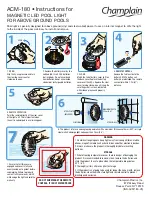
ACM-180
Brand: Champlain Pages: 2

BFH2242M
Brand: Bionaire Pages: 12

21222292
Brand: Sonnenkonig Pages: 48

CRISTAL MAGIC Pool Pilot Digital 36
Brand: R B F International Pages: 19

FREESYSTEM
Brand: DELTACALOR Pages: 47

050-HA-50070
Brand: DELLA Pages: 14

014-HG-PH42
Brand: Belleze Pages: 24

5812
Brand: Lasko Pages: 4

EHXD
Brand: Daikin Pages: 4

AD 7815
Brand: Adler Europe Pages: 72

AD 77
Brand: Adler Europe Pages: 60

AD 7709
Brand: Adler Europe Pages: 64


