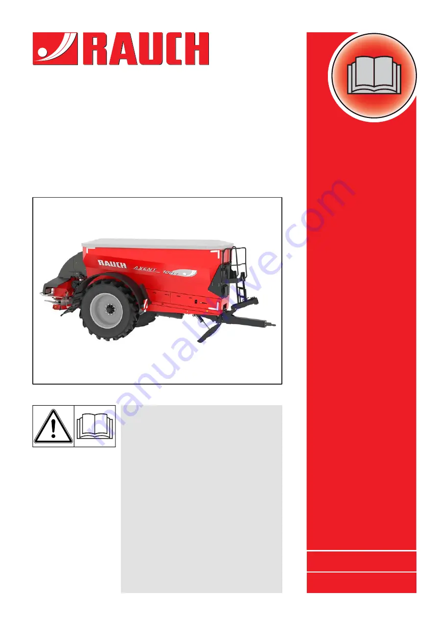
background image

OPERATOR'S MANUAL

AXENT

5901645-

e

-en-0219

Please read carefully 
before using the 
machine.

Keep for future reference.

This instruction manual/assembly
instruction is to be considered as part of
the machine. Suppliers of new and sec-
ond-hand machines are required to
document in writing that the instruc-
tion manual/assembly instruction was
delivered with the machine and
handed over to the customer.

Original manual

Summary of Contents for AXENT Series

Page 1: ...reference This instruction manual assembly instruction is to be considered as part of the machine Suppliers of new and sec ond hand machines are required to document in writing that the instruc tion m...

Page 2: ...n your machine Please note that damage caused by incorrect operation or improper use is not covered by warranty claims Technical improvements We are continuously improving our products Therefore we re...

Page 3: ...ing the machine 8 3 5 2 Filling the machine 8 3 5 3 Checks before start up 9 3 5 4 Hazard zone 9 3 5 5 Operation 10 3 5 6 Wheels and brakes 10 3 6 Using fertiliser and lime 11 3 7 Hydraulic system 11...

Page 4: ...ding unit 46 5 Transport without tractor 49 5 1 General safety instructions 49 5 2 Loading and unloading parking 49 6 Commissioning 51 6 1 Accepting the machine 51 6 2 Operating licence 52 6 2 1 Germa...

Page 5: ...ine on the ISOBUS terminal 94 7 4 4 Set the working width 97 7 4 5 Setting the drop point 100 7 4 6 Adjusting the application rate 101 7 4 7 Spreading in the headland 102 7 4 8 Spreading sideways on t...

Page 6: ...belt scraper tight 140 9 10 Maintenance of chassis and brakes 141 9 10 1 Checking the condition and function of the brake system 141 9 10 2 Draining the air tank 142 9 11 Maintenance of hydraulic syst...

Page 7: ...ufacturer Only genuine spare parts from the manufacturer may be used as spare parts Only persons who are familiar with the features of the machine and aware of the dangers are permitted to use service...

Page 8: ...Intended use 1 2...

Page 9: ...ew owner The operator s manual is intended for the operator of the machine and anyone involved in operating and maintaining it It must be read understood and applied by all persons entrusted with the...

Page 10: ...ront of these instructions Handling instruction 2 3 2 Listings Listings without a specific sequence are shown with bullet points level 1 and dashes level 2 Property A Point A Point B Property B 2 3 3...

Page 11: ...observe this operating manual before the start up Warning notes on the supplier components can be found in the respective supplier documentation These warning instructions must also be observed 3 2 Si...

Page 12: ...warns of a possible dangerous situation for the health of persons Ignoring these warnings will result in very serious injury Always observe the measures described to prevent this danger n CAUTION Type...

Page 13: ...the operator It is the operator s responsibility that the machine is used as intended 3 4 1 Personnel qualifications Before starting any work on or with the machine all persons who are involved in op...

Page 14: ...parking the machine Park the machine on level solid ground Before uncoupling the machine check that it is secured against tipping over and rolling away Has the parking brake been applied Is the suppor...

Page 15: ...a great hazard caused by the tractor rolling away or by machine movements which may have fatal consequences The following figure displays the hazard zones of the machine Figure 3 1 Hazard zones aroun...

Page 16: ...els and brakes The chassis of the towed machine is exposed to high loads due to the high total weight and the driving terrain To ensure operational safety pay particular atten tion to the following po...

Page 17: ...n connecting the hydraulic hoses to the tractor ensure that the hydraulic system is depressurised both on the tractor and the machine side Attach the hydraulic hoses of the tractor and the spreader hy...

Page 18: ...ms is to be carried out by qualified technicians only 3 8 2 Wear parts The maintenance and service intervals described in the present operator s manual are to be strictly adhered to at all times Furth...

Page 19: ...e empty container on level solid ground and secured against rolling away Depressurise the hydraulic system before carrying out any maintenance and servicing work Disconnect the power supply before wor...

Page 20: ...ssible towing load and vertical load of the trailer unit as well as the permissible axle load Observe the permissible brake load the permissible tyre load capacity and the permissible tyre pressure Is...

Page 21: ...ufficient visibility Another person is required for directing the driver if this is not ensured e g when reversing Observe the permissible maximum speed Avoid sudden curves when driving uphill and dow...

Page 22: ...ontour marks 2 Warning not transport passengers 3 Warning of high voltage electrical power lines 4 Read the operating manual warning notice 5 Warning of material ejection 6 Instruction for PTO shaft s...

Page 23: ...tions rear 1 Warning sign 2 Tail light brake light turn signals 3 Tail light brake light red reflectors 4 Mudguard extension 5 Red reflectors 6 Moving parts warning notice 7 Red reflector stripes 8 Re...

Page 24: ...ons ring eyelet in hopper 3 Cleaning flap instruction 4 Warnings of danger of explosion under the container not visible here 5 Warnings of moving parts behind the folding side covers 6 Cover 7 Deflect...

Page 25: ...ring sliders Prevents body parts from being drawn in by the agitator Contains the lighting system for the rear lighting with warning sign tail light brake light warning lights and turn indicators Rear...

Page 26: ...ual and warnings Read and observe the operating manual and warning notices before starting the machine The operating manual provides detailed instructions on operating the machine and provides useful...

Page 27: ...d zone between the tractor and the machine No passengers Danger of slipping and injury Do not climb onto the platform of the machine during spreading work and transport Danger of explosion The nitroge...

Page 28: ...nameplate PTO shaft speed The rated speed of the PTO shaft is 750 rpm Ring eyelet on the frame Identification of the holder for attachment of the lifting harness Lubrication points Cleaning flap is op...

Page 29: ...m axle Nameplate and serial number of towing bar Name plate trailer hitch France DREAL registration plate 3 AXENT PTAC Masse maxi essieu 1 Masse maxi attelage R ceptionn le par la DREAL ALSACE 15 000...

Page 30: ...ed axle load 4 Admissible total weight Rauch Landmaschinenfabrik GmbH Landstr 14 76547 Sinzheim Germany Brand Serial No Maschine Model Unladen Mass RAUCH RLxxxxxxxxxxxxxxx min xxx kg max xxx kg Made i...

Page 31: ...ing to regulations and must be ready to operate at all times They not be covered or obscured by dirt The machine has been equipped with front rear and side identification according to regulations at t...

Page 32: ...Safety 3 26...

Page 33: ...203 4 2 Description of the machine Use the AXENT large area spreader in accordance with the chapter Intended use on page 1 The machine consists of several assemblies each with a specific function Con...

Page 34: ...4 2 1 Basic machine Figure 4 1 Assemblies and function of the machine AXENT side view 6 7 8 1 Hopper 2 Rear view camera 3 Wheel 4 Parking brake 5 Service brake 6 Support stand 7 Folding side cover 8 U...

Page 35: ...Figure 4 2 Assemblies and function of the machine AXENT front view 1 Filler plug oil tank 2 Transport storage place for wheel chock 3 Conveyor belt 4 Maintenance flap 5 Ladder 6 Hose and cable storag...

Page 36: ...Technical data 4 30 Figure 4 3 Assemblies and function of the machine AXENT rear view 1 Pre metering slider 2 Comb roller 3 Removable separating plate...

Page 37: ...eading unit Figure 4 4 Assemblies and function of the AXIS PowerPack fertiliser spreading unit 1 Coupling points 2 Hopper 3 Adjustment centre drop point 4 Spreading disc drive 5 Spreading disc 6 Sprea...

Page 38: ...owerPack lime spreading unit Figure 4 5 Assemblies and function of the LIME PowerPack lime spreading unit 1 Coupling points 2 Funnel 3 Spreading disc protection 4 Deflector bracket 5 Spreading disc dr...

Page 39: ...k for spreading lime AXIS PowerPack for spreading fertiliser NOTICE Some models are not available in all countries Type AXENT 100 1 Steering axle AXENT 100 1 Rigid axle Pneumatic brake system Hydrauli...

Page 40: ...5 m France 4 60 m Conveying capacity conveyor belt 1 max 1 600 kg min Hydraulic pressure max 280 bar Oil quantity hydraulic system max 100 l min Track width 2 2 00 m Standard tyres 3 520 85 R42 AC85...

Page 41: ...for the wheel load With towing bar for top hitching DOH 12 000 kg With towing bar for bottom hitching DUH 13 000 kg Weight of AXIS PowerPack fertiliser spreading unit approx 350 kg Weight of LIME Pow...

Page 42: ...tre of gravity with full container B Centre of gravity with empty container NOTICE The centre of gravity depends on the coupling variant the axle position and the filling quantity of the container L1...

Page 43: ...4 Figure 4 7 Centre of gravity in top hitching A Centre of gravity with full container B Centre of gravity with empty container L1 H1 H2 L2 L3 L4 A B Length Top hitching mm L1 337 L2 721 L3 2390 L4 45...

Page 44: ...ty weight mass stated on the nameplate refers to the standard version Data AXENT P1 1 P pneumatic brake system H2 2 H hydraulic brake system Admissible total weight 3 3 Observe the entries in the oper...

Page 45: ...gravity with full container B Centre of gravity with empty container NOTICE The centre of gravity depends on the coupling variant the axle position and the filling quantity of the container L1 H1 H2...

Page 46: ...th 13 000 kg axle load 5 m 4 60 m Conveying capacity conveyor belt 1 max 1 600 kg min Hydraulic pressure max 280 bar Oil quantity hydraulic system max 100 l min Track width 2 3 00 m Standard tyres 3 5...

Page 47: ...s to the standard version Data AXENT Admissible total weight 1 1 Observe the entries in the operating licence for the wheel load 15 000 kg Weight of AXIS PowerPack fertiliser spreading unit approx 350...

Page 48: ...gravity with full container B Centre of gravity with empty container NOTICE The centre of gravity depends on the coupling variant the axle position and the filling quantity of the container L1 H1 H2 L...

Page 49: ...tainer Approx 200 l Mass flow 2 2 Max mass flow depending on the fertiliser type 500 kg min Hydraulic pressure 200 bar Hydraulic performance 60 l min Data LIME PowerPack Total width with deflector bra...

Page 50: ...g LI 173 for a load capacity of 6 500 kg NOTICE Some models are not available in all countries Wheel size Track width in m Rigid axle 2 m Steering axle 2 m Rigid axle 3 m Tyre pressure in bar Load cap...

Page 51: ...y 5 000 kg at 40 km h Load capacity 6 500 kg at 25 km h VF 380 90 R46 HC1000 173D 2 25 3 2 4 4 3 00 VF 380 105 R50 HC1000 176D 2 25 2 4 3 4 3 00 VF 420 95 R50 SprayBib TL 177D 3 00 1 8 3 0 VF 480 80 R...

Page 52: ...t for Germany 4 5 2 Special equipment for lime spreading unit LIME PowerPack lime spreading unit with comb roller Parts set of granulate discs for LIME PowerPack with S4 spreading disc set Shaker moto...

Page 53: ...onsists of intensive LED light and is specifically aimed at the spreading fans Possible incorrect settings or clogging at the dispensing gates are recognised immediately Moreover the user can respond...

Page 54: ...Technical data 4 48...

Page 55: ...t must ensure the machine is transported appropriately Unauthorised persons are to be kept away from the transport route Cordon off the affected areas Cautiously transport the machine and handle it wi...

Page 56: ...Transport without tractor 5 50...

Page 57: ...s for the ball valves of the towing bar suspension 1 AXENT H ISOBUS electronic machine control unit with operating manual 1 type approval 21 StVZO Road Traffic Licensing Regulation Germany For France...

Page 58: ...our local registration office The licence is granted by assigning a separate official number plate stamping the number plate and issuing part 1 and part 2 of a registration certificate The towed AXENT...

Page 59: ...or public road traffic For additional identification warning sign lighting please contact your dealer or importer 6 3 Tractor requirements To ensure the machine is used safely as intended the tractor...

Page 60: ...he specialist workshop may carry out retrofitting work on the steering axle n CAUTION Material damages due to unsuitable drive shaft The machine is delivered with a drive shaft that is designed accord...

Page 61: ...e shaft onto the gear journal until the sliding pin engages in the annular groove 7 Release the sliding pin Figure 6 3 Fitting the universal drive shaft on the gear journal 8 Apply the protective plat...

Page 62: ...56 Dismantling instructions Dismantle the universal drive shaft in the opposite order as when installing it 11 Fasten the retaining chain through the hole in the ring eyelet Figure 6 5 Fastening the...

Page 63: ...s that comply with the technical require ments of the machine Use the vehicle s documentation to check if your tractor is suitable for the machine n DANGER Danger to life due to inattention or faulty...

Page 64: ...support stand 3 Hydraulic line for hopper cover 4 Hydraulic line for hopper cover 5 Pneumatic control line compressed air brake 6 Pneumatic line for compressed air tank compressed air brake 7 Hydrauli...

Page 65: ...e with 2 red rubber bands on the handle fold in the support stand 4 Hose with 1 grey rubber band on the handle unfold the support stand 3 Connect the hydraulic hoses 3 and 4 of the support stand to th...

Page 66: ...ion the tractor s ball coupling exactly under the machine s coupling bracket 3 Apply the handbrake of the tractor 4 Actuate the control valve on the tractor until the support stand is completely retra...

Page 67: ...Hitch coupling variant C 1 Start the tractor The PTO shaft is switched off The hydraulic system is switched off 2 Drive the tractor up to the machine 3 Adjust the height of the machine s hydraulic sup...

Page 68: ...pment Figure 6 9 Gyroscope and holder NOTICE Install the gyroscope and its holder on the tractor Observe the installation instructions in the operating manual for the ISO BUS TRAIL Control Midi from M...

Page 69: ...s can cause damage to the drive shaft the transmission or the machine Check the clearance between the machine and the tractor Make sure there is enough space at least 20 to 30mm between the outer pipe...

Page 70: ...he tightness and function of the brake system after the coupling process and each time before driving To do so operate the service brake of the tractor Do not drive with the coupled machine until the...

Page 71: ...f the brake pressure regulator to the filling quantity of the machine n DANGER Danger to life due to defective brake system There is a danger to life if the brake system is used improperly or is defec...

Page 72: ...pull chain serves as a breakaway coupling in the event of accidental uncoupling of the machine from the tractor Observe the connection order See Figure 6 6 Make sure the pull chain is connected to th...

Page 73: ...1 only when the machine is attached to the tractor and the compressed air lines are connected Figure 6 13 Releasing the parking brake 1 Parking brake 2 Service brake Hydraulic brake system Figure 6 14...

Page 74: ...g axle special equipment The axial reciprocating pump ensures a constant operating pressure at a univer sal drive shaft speed of 650 to 1300 rpm The hydraulic folding support stand and the hydraulic t...

Page 75: ...70 The large area spreader is empty The large area spreader is coupled to the tractor The large area spreader and the tractor are secured against rolling away The cover is folded up The adjustment le...

Page 76: ...edge of the container Secure the forklift against rolling away Place all parts of the feeder mesh securely on the pallet Figure 6 16 Unlocking the holders 1 Adjustment lever 2 Locking the mesh suppor...

Page 77: ...en the holder and the spreading unit hopper The separating plate is now dismantled 1 Adjustment lever left in direction of travel hose storage place Figure 6 17 Adjustment lever 1 Remove the adjustmen...

Page 78: ...unit regularly reinstall the separating plate and the feeder mesh Installing the feeder mesh AXIS PowerPack page 74 at the machine outlet before attaching the AXIS PowerPack spreading unit Figure 6 20...

Page 79: ...sheet guide is inserted in the guide holder at the separating plate 4 Push the fork 2 onto the round tube with the handle 1 5 Turn the lock 3 90 degrees with the adjustment lever The separating plate...

Page 80: ...oning parts Figure 6 23 Installing the holders of the feeder mesh A Mesh support with lock B Mesh support with positioning parts 1 Install the mesh supports 4x with a lock at the positions A 2 Install...

Page 81: ...mesh onto the mesh supports and push it into the plastic hook 2 The positioning parts 1 engage exactly in the feeder mesh Figure 6 24 Installing the feeder mesh 1 Positioning part 2 Plastic hook 4 In...

Page 82: ...g the feeder mesh 1 Adjustment lever 2 Locks 5 Turn the locks 90 with the adjustment lever Figure 6 26 Securing the feeder mesh in the hopper 6 Check whether all parts of the feeder mesh are fitted co...

Page 83: ...preading unit and pallet with a forklift 3 Drive the forklift up to the large area spreader n DANGER Danger to life due to inattention or faulty operation There is fatal danger of people becoming crus...

Page 84: ...nit for secure fitting in the hook 5 Drive away the forklift 6 Close the catch hook 9 Check the tight fitting of the machine 7 Insert the bottom pin of the spreading unit into the elongated hole of th...

Page 85: ...t the electrical and hydraulic lines 6 8 Converting spreading units The spreading unit is removed in the opposite order as its attachment The cover is open The mudguard extensions have been detached f...

Page 86: ...AXIS PowerPack page 72 6 7 5 Installing the feeder mesh AXIS PowerPack page 74 When converting to the LIME PowerPack lime spreading unit 6 7 2 Dismantling the feeder mesh LIME PowerPack page 70 6 7 3...

Page 87: ...cess Make sure the parking brake is applied n CAUTION Inadmissible overall weight If the permissible total weight is exceeded this will affect the oper ational safety and road safety of the vehicle la...

Page 88: ...Prerequisites The hydraulic system is switched on 1 Open the hopper cover of the machine 2 Fill the machine evenly Use a front end loader or auger for this purpose 3 Check the level in the hopper for...

Page 89: ...eable ladder 4 Snap in pin of the folding ladder 5 Platform n WARNING Risk of injury due to falling from the platform The platform is more than 1 50 m above the ground There is a danger of falling ont...

Page 90: ...ree Figure 6 37 Lowering the top part of the ladder 3 Pull the folding ladder until the snap pins 1 disengage 4 Fold down the ladder Figure 6 38 Unfolding the bottom part of the ladder NOTICE Climb on...

Page 91: ...ain in accordance with the instructions in chapter 3 Safety page 5 5 Folding up the bottom ladder 6 Snap the snap pin 1 into the groove of the snap fasteners Figure 6 39 Folding in the ladder 7 Push u...

Page 92: ...o the rear approx 7 m B Radius 5 80 m C Diameter of the field of vision to the right and left 10 m W Viewing angle 120 1 Rear view camera Figure 6 42 Screen shot of rear view camera NOTICE The rear vi...

Page 93: ...machines are manufactured with care deviations in the spreading or other faults cannot be ruled out even if they are used as intended The reasons for this may be Changes to the physical properties of...

Page 94: ...ard types of fertiliser e g calcium ammonium nitrate kieserite in crease the wear ALWAYS use the feeder mesh in conjunction with the AXIS PowerPack fertiliser spreading unit to block clogging e g due...

Page 95: ...mers controlled by the machine control unit stop conveyor belt pre metering slider comb roller hopper cover Figure 7 1 Closing the cover 1 Handles 2 Plastic clips 3 Tieback 4 Bolt n WARNING Danger due...

Page 96: ...s ready for operation 1 Grip and pull the tieback by hand The cover closes downwards Figure 7 2 Pulling the tieback 2 Grip the cover by the han dles and lower it slowly Figure 7 3 Grip the cover by th...

Page 97: ...r belt is described in a separate operating manual for the electronic control This operating manual is part of the AXENT ISOBUS electronic control NOTICE The spreading unit hopper will not be reported...

Page 98: ...e Page 72 et seq Attaching the fertiliser spreading unit to the large area spreader Page 69 Closing the pre metering sliders Filling the machine Page 81 Machine settings working width application rate...

Page 99: ...alibration test Check the fertiliser distribution for the working width with a practice test kit special equipment Use only those fertilisers listed in the fertiliser chart Let us know if you are miss...

Page 100: ...th normal fertilisation A symmetrical spreading pattern is created by field spreading with normal fer tilisation The fertiliser is distributed evenly if the spreading setting is correct see informatio...

Page 101: ...ter them in the Fertiliser settings menu Application rate Working width Drop point Limited border spreading mode select Limited bd Quantity reduction 2 Activate the limited border spreading function i...

Page 102: ...fertiliser chart and enter them in the Fertiliser settings menu Application rate Working width Drop point Limited border spreading mode select Full bord 2 Activate the full border spreading function...

Page 103: ...parts can be sheared off crushed or amputated due to con tact with the spreading equipment spreading discs spreader vanes Body parts or objects may be caught and pulled in Do not remove the deflector...

Page 104: ...s caused by mechanical components and escaping fertiliser Never dismantle or install the spreading discs while the tractor engine is running Turn the tractor motor off Remove the ignition key 1 Adjust...

Page 105: ...t on the hub remove any dirt if necessary 2 Carefully position the cap nut do not tilt it 3 Tighten the cap nut with approx 38 Nm 4 Check the free passage between the spreader vane and the outlet To d...

Page 106: ...mbers The fertiliser is ejected earlier This results in spreading patterns for smaller working widths Adjusting in the direction of large numbers The fertiliser is ejected later and spread further to...

Page 107: ...large area spreader is equipped with an electronic slide actuator for setting the spreading quantity on the fertiliser spreading unit The electronic metering slide actuator is described in a separate...

Page 108: ...the tracks precisely Limited border spreading When spreading in the headland in limited border spreading mode speed reduction drop point adjustment and quantity reduction Figure 7 12 Limited border sp...

Page 109: ...the metering slide when the following condition is met The end of the spreading fan on the field E is about half the working width 4 to 8 m away from the field border of the headland The distance of...

Page 110: ...deways on the slope You can counter act this drifting movement with the kingpin steering special equip ment Use the offset function on your steering computer for this purpose Figure 7 14 Kingpin steer...

Page 111: ...der mesh and separating plate Attaching the lime spreading unit to the large area spreader Page 57 Closing the pre metering sliders Filling the machine Page 81 Making machine settings density travel s...

Page 112: ...or even distribution of the lime ex works Figure 7 15 Normal spreading pattern drop point in neutral position Both marks for the neutral position are centred Figure 7 16 Drop point in neutral position...

Page 113: ...ards or back Figure 7 17 Setting the drop point 1 Fixing screws 2 Neutral position mark 3 Adjusting screw Undo the fixing screws 1 with a size 36 spanner on each side Insufficient lime in the middle 1...

Page 114: ...Excessive lime in the middle 1 Turn the adjusting screw 3 with a size 36 spanner to move the sliding part to the front in the direction of travel Figure 7 19 Excessive lime in the middle The drop poi...

Page 115: ...r opening 3 Start lime operation by means of the AXENT ISOBUS machine control unit The conveyor belt starts The comb roller starts NOTICE The overload function of the machine in connection with the li...

Page 116: ...XIS PowerPack The spreading discs have been dismantled See Dismantling the spreading discs on page 98 LIME PowerPack The lime spreading unit has been dismantled n DANGER Danger due to rotating spreadi...

Page 117: ...material at the spreading unit by means of the AXENT ISOBUS machine control unit 4 Follow the instructions on the screen 5 Clean the machine after completely emptying the spreader hopper See chapter 9...

Page 118: ...brake The parking brake is applied Figure 7 20 Releasing the manual parking brake 1 Parking brake 2 Service brake n WARNING Danger due to tipping The AXENT 100 1 large area spreader is a single axle...

Page 119: ...hand crank of the parking brake clockwise The parking brake is applied 2 Remove the wheel chocks from the transport storage place at the mudguard 3 Push the sliding pin 1 and open the wheel chocks Fig...

Page 120: ...e electrical connections from the tractor 8 Protect all plug connections with the dust caps 9 Uncouple the universal drive shaft from the tractor 10 De pressurise the hydraulic system of the tractor f...

Page 121: ...ided 15 Place all cables and hoses on the console above the towing bar in the holders provided for this purpose Figure 7 24 Storage console for cables hydraulic hoses and pneumatic lines 1 Storage pla...

Page 122: ...Spreading operation 7 116...

Page 123: ...preader hopper The universal drive shaft is not connected or switched on The machine control unit is not switched on The AXENT container is empty The fertiliser spreader is full The level sensors in t...

Page 124: ...Faults and possible causes 8 118...

Page 125: ...manufacturer This is ensured for example only by genuine spare parts Only qualified personnel are allowed to repair tyres and wheels with suitable assembly tools Before starting any cleaning maintenan...

Page 126: ...spreader Components Maintenance work Maintenance schedule Comment Wear parts and screw connections Check regularly Page 127 Cleaning Perform after each use Page 125 Towing eye ball coupling Check for...

Page 127: ...nance work Maintenance schedule Comment Nitrogen tank External inspection at the latest every 2 years Check nitrogen tank and connections for damage before driving Hydraulic hoses Check condition Repl...

Page 128: ...ampere fuse The fuses are behind the maintenance flap Checking the electrical cables Visually inspect all electrical cables for wear Pay particular attention to external damage or breakages Checking t...

Page 129: ...the level sensors n WARNING Risk of injury The electronic control is checked in real time This means that the machine components immediately execute the selected function Make sure everybody leaves th...

Page 130: ...ame Gear unit After the first 50 operating hours Then every 500 operating hours 1 5 l DIVINOL MCL ISO 320 Alternative oil SAE 90 On board hydraulic Vario drive After the first 100 operating hours or a...

Page 131: ...mponents 9 3 1 Cleaning the bearings of the guide rollers Dust and dirt accumulate at the guide rollers of the conveyor belt during spreading operation Clean the guide rollers You must open the side c...

Page 132: ...l parts with an environmentally friendly anti corrosion agent A suitable polishing kit can be ordered from authorised dealers to treat the rust spots 4 Clean the guide rollers with a soft water jet 5...

Page 133: ...you have the condition of the towed large area spreader checked after each season by your specialist dealer paying particular atten tion to its fastening components hydraulic system and hoses Spare pa...

Page 134: ...vicing 9 128 9 5 Recovery of the machine If the tractor can no longer pull the machine proceed as follows to recover the machine from the field Attach a rope around the axle body Figure 9 6 Recovering...

Page 135: ...d off crushed or amputated due to contact with the spreading equipment spreading discs spreader vanes Body parts or objects may be caught and pulled in Do not remove the deflector bracket fitted on th...

Page 136: ...jury from heavy spreading discs The spreading discs of the LIME PowerPack lime spreading unit weigh 25 kg Strains cuts on the limbs and back aches can be caused by handling the spreading discs Handle...

Page 137: ...spreading disc 2 Locating pin The following assembly procedure is described with the left spreading disc Install the right spreading disc also according to these instructions 1 Place the left spreadin...

Page 138: ...cocks have been dismantled and supplied together with the machine The height of the coupling points may vary due to the characteristics of your tractor e g small wheels low coupling points You may the...

Page 139: ...between bottom edge of container frame and floor front Setting the towing bar height 2 Fit the levers on the stopcocks 3 Open both stopcocks The hydraulic circuit for the towing bar suspension and th...

Page 140: ...Figure 9 12 Closing the left stopcock 7 Check the towing bar suspension cylinder The piston rod must be extended min 50 mm and max 140 mm 50 mm x 140 mm Figure 9 13 Extending the piston rod NOTICE Co...

Page 141: ...11 Dismantle both handles of the ball valves and stow them safely away 8 Retract the support stand with the hydraulic control unit of the tractor 9 Set the pressure to 70 bar The support stand is ret...

Page 142: ...sition 1 Conveyor belt 2 Hopper wall X Measure the distance between conveyor belt and hopper wall on left right Adjust the drive roller if the deviation between the two sides is greater than 20 mm The...

Page 143: ...ck the tension of the conveyor belt after the first few hours of operation or if you notice any slippage at the conveyor belt The tension pulleys of the conveyor belt are located at the front between...

Page 144: ...on each side The marking plate should be in the area of the same mark ing tooth A on both sides The scale 1 of the deflection roller should also coincide on each side If the position of the mark ings...

Page 145: ...belt scraper 9 9 2 Adjusting the holder for the belt scraper 1 Undo the five screws 3 of the clamping plate 1 2 Remove the belt scraper 2 Figure 9 20 Dismantling the clamping plate 1 3 2 1 Take a 4 mm...

Page 146: ...belt 4 Adjust the position of the holder above the elongated holes 5 Re tighten the screws 1 Figure 9 22 Adjusting the position of the holder 1 1 Re apply the belt scraper 1 Pay attention to the posit...

Page 147: ...e only the brake pads specified for the axles n WARNING Danger of accident due to improperly executed work Improperly executed work on the chassis and brake system will impair the operational safety o...

Page 148: ...ake circuit and accumulate in the air tank To prevent corrosion related damage to the compressed air brake system drain the air tank daily 1 Pull the actuating pin 1 with a finger The tilt valve opens...

Page 149: ...essurise the hydraulic system before carrying out any work Stop the tractor engine and secure it against being switched on again Allow the hydraulic system to cool down Always wear protective goggles...

Page 150: ...rt of the spreading sea son Replace the hydraulic hoses if the storage and usage time is exceeded 9 11 2 Replacing hydraulic hoses Preparation Make sure the hydraulic system is de pressurised and has...

Page 151: ...raulic hose Tighten the hose fittings 7 Secure the hydraulic hose in place with the hose fittings 8 Check the position of the new hydraulic hose The hose routing must be identical to that of the old h...

Page 152: ...er between the filter cartridge and the adjustment unit for the towing bar suspension 7 Screw on the new oil filters 2 Open the hydraulic tap 1 3 Allow the residual oil to flow into the collection con...

Page 153: ...ial damage to the machine hydraulics and the machine parts moved by the hydraulic system can be caused by a wrong type of oil or by mixing different types of oil Use only the permitted oil types descr...

Page 154: ...ponents of the hydraulic system are The hydraulic cylinders of the pre metering sliders The hydraulic motor of the conveyor belt drive The hydraulic cylinders used to drive the hopper cover Checking t...

Page 155: ...veyor belt drive Actuating functions hydraulic cylinder 1 for the hopper cover front and rear Figure 9 32 Hydraulic cylinder hopper cover 1 Regularly check the conveyor belt motor but at least before...

Page 156: ...t can cause stress cracks on wheels and tyre damage Keep the contact surfaces to the tyre and to the wheel hub rust free Replace torn or deformed wheels or wheels damaged in any other way Replace whee...

Page 157: ...of a wheel of the large area spreader can result in serious accidents involving personal injury Change the wheel only on the empty large area spreader attached to the tractor To change the wheel the l...

Page 158: ...pwise and crosswise with a torque wrench Tighten the wheel nuts with a tightening torque of 560 Nm Screw and tighten all 10 wheel nuts per wheel The wheel nuts loosen due to setting procedures during...

Page 159: ...1 Lubrication points of AXENT basic machine The lubrication points are distributed and marked over the entire machine You can recognize the lubrication points by this sign Figure 9 35 Sign for lubric...

Page 160: ...ing 9 154 Figure 9 37 Brake linkage 1 Lubrication point support stand Figure 9 38 Support stand 1 Lubrication point Figure 9 39 Hydraulic cylinder support stand 1 Lubrication point deflection roller F...

Page 161: ...nd servicing 155 9 9 13 2 Lubrication points of the LIME PowerPack lime spreading unit 1 Lubrication points towing bar Figure 9 41 Towing bar 1 1 1 Lubrication point container Figure 9 42 Lubrication...

Page 162: ...General maintenance and servicing 9 156...

Page 163: ...e sewers The ingress of oil into the sewage system must be pre vented by building dams made of sand and or earth or by other suitable damming means n WARNING Environmental pollution caused by inapprop...

Page 164: ...d implement them 1 All components auxiliary and operating materials from the machine must be removed by specialist staff Hereby these components and substances must be cleanly separated into categorie...

Page 165: ...Faults 117 Setting the speed 91 Coupling Ball head 60 Hitch 61 Pin 61 D Discharging residual material 110 Disposal 157 F Faults 117 Fertiliser 10 Fertiliser chart 93 Filling level 83 Full border spre...

Page 166: ...ling 29 30 61 Platform 29 30 Level control 83 R Reflector 25 S Safety 5 25 11 Accident prevention 8 Fertiliser 10 Maintenance 13 Operation 8 Reflector 25 Safety equipment 16 Servicing 13 Sticker 20 Tr...

Page 167: ...Tyre pressure 44 U Universal drive shaft Dismantling 56 Installation 54 Safety equipment 18 Urea 93 Use Intended 1 User instructions 3 W Warning notes Stickers 20 Warnings Meaning 5 Wear parts 12 127...

Page 168: ...Index D...

Page 169: ...g manual must be observed In all cases of doubt contact our sales representatives or the factory directly Warranty claims must be submitted to the factory by 30 days at the latest after occurrence of...

Page 170: ......

Reviews: