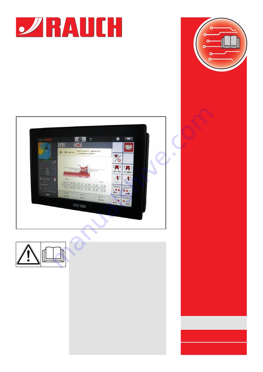
background image

AERO ISOBUS

Please read carefully

before using the

machine!

Keep for future use

This operator's and assembly manual is
an integral part of the machine. Suppliers
of new and second-hand machines are
required to document in writing that the
operator's and assembly manual was
delivered with the machine and handed
over to the customer.

Version 2.10.00

5903001-

c

-en-0522

Original instructions

Complementary instructions

Summary of Contents for AERO ISOBUS

Page 1: ...manual is an integral part of the machine Suppliers of new and second hand machines are required to document in writing that the operator s and assembly manual was delivered with the machine and hand...

Page 2: ...machine control unit AERO ISOBUS has been calibrated at the factory for the fertilizer spreader with which it was supplied It cannot be connected to another machine without new calibration Please ente...

Page 3: ...s 13 2 2 4 Other icons 14 2 3 Structural menu overview 16 3 Attachment and installation 17 3 1 Tractor requirements 17 3 2 Connections sockets 17 3 2 1 Power supply 17 4 Operation 18 4 1 Switching on...

Page 4: ...n functions 53 4 13 WIFI module 55 5 Spreading operation 57 5 1 Working with sections 57 5 2 Spreading with the AUTO km h operating mode 57 5 3 Spreading with the MAN km h operating mode 58 5 4 Automa...

Page 5: ...are classified according to the severeness of the risk and the probability of its occurrence The warning symbols draw attention to the unavoidable residual risks inherent in the design to which users...

Page 6: ...is a note General information containing application tips and particularly useful information but which constitutes neither warnings nor hazards 1 3 Notes on text descriptions 1 3 1 Instructions and p...

Page 7: ...n be made selection lists text or number entries starting a function The various menus and buttons of the machine control unit are illustrated in bold letters The hierarchy and the path to the request...

Page 8: ...al in the corresponding operator s manual 2 1 Display The display shows the current status information as well as the selection and input options for the electronic machine control unit The most impor...

Page 9: ...of metering units 8 Application rate adjustment for the left boom section 9 Display of boom type mineral fertilizer spreader 10 Current application rate from the fertilizer settings or the task contro...

Page 10: ...orresponding display field in the touch screen The available options are displayed in a list u Select the new value to be assigned to the display field u Press the OK button The working screen is disp...

Page 11: ...spreading operation START 2 1 4 Display of sections Fig 4 Display of the section states 1 Activated sections on entire working width 2 Reduce right section button 3 Right section is reduced by severa...

Page 12: ...ght next page Back to the previous menu Switch from a menu window directly to the main menu Switch between working screen and menu window Cancellation closing the dialog window 2 2 2 Menus Icon Meanin...

Page 13: ...ding operation has started stop the application rate regulation Activate Distance Control option Distance Control option is active Reset the quantity adjustment to the pre set application rate Switch...

Page 14: ...antity adjustment right minus Increase left sections plus Reduce left sections minus Increase right sections plus Reduce right sections minus 2 2 4 Other icons Symbol Meaning Fold in start sections an...

Page 15: ...Lock boom Unlock boom Automatic axle suspension active Automatic axle suspension switched off Lift boom Lower boom Inclination of boom lift left Inclination of boom lift right Automatic retensioning o...

Page 16: ...2 3 Structural menu overview 2 Layout and function 16 5903001 AERO ISOBUS...

Page 17: ...tractor for connecting the machine control unit to the ISOBUS 9 pin terminal plug ISO 11783 for connecting an ISOBUS terminal to the ISOBUS The power supply of the machine control unit is implemented...

Page 18: ...of the machine control unit is displayed Subsequently the machine control unit displays the activation menu for a few seconds u Press the enter key The working screen then appears 4 2 Navigation with...

Page 19: ...revious menu windows tabs using the left right arrow keys n Exiting menus u Confirm settings by pressing the Return key You will return to the previous menu u Press the Working screen main menu key Yo...

Page 20: ...regarding spreading work carried out and functions for weighing operation 4 11 Weighing Trip counter In addition to using the sub menus you can select the Lift lower and Inclination to the left right...

Page 21: ...o calibrate or maintain the hydropneumatic suspension its height can be adjusted manually Please observe the operator s manual for your machine CAUTION Risk of injury from adjusting the hydropneumatic...

Page 22: ...selected from the fertilizer chart 4 5 4 Fertilizer charts Appl rate kg ha Input of target value for the application rate in kg ha 4 5 1 Application rate Manufacturer Fertilizer manufacturer input Com...

Page 23: ...also enter or adjust the application rate directly via the working screen u Press the Appl rate kg ha 1 button on the touch screen The number input window is displayed Fig 8 Entering the application r...

Page 24: ...ke sure to execute a calibration The calibration factor for this fertilizer is determined precisely 4 5 3 Calibration You execute the calibration to calibrate the precise amount of fertilizer Fertiliz...

Page 25: ...on 2 Selecting the section on which the calibration test is performed u Enter the new designation in the input field Fertiliser name u Select the desired section for the calibration test w To do so ch...

Page 26: ...ved in the machine control unit The display switches to page 3 The metering roller now fills the spreader tank and automatically stops after 5 s The display switches to page 4 u Empty the fertilizer c...

Page 27: ...ation test has been performed and is therefore complete 4 5 4 Fertilizer charts In this menu you can create and manage your own fertilizer charts Selecting a fertilizer chart affects the machine ferti...

Page 28: ...display shows the selection window u Press the option Open and back to fertiliser settings The Fertiliser settings menu is displayed and the selected element is loaded into the fertilizer settings as...

Page 29: ...rop point and the normal disc speed The machine control unit will move the drop point to the value stored in the fertilizer chart Copying an existing fertilizer chart u Select the desired fertilizer c...

Page 30: ...ilizer chart is displayed Fig 12 Managing the fertilizer chart via the touch screen 1 Button Application rate 2 Button Fertiliser chart u Enter the new value in the input field u Press OK The new valu...

Page 31: ...keys Sub menu Meaning Description AUTO MAN mode Specifying automatic or manual operating mode 4 6 1 AUTO MAN mode MAN km h Setting the manual speed only influences the respective operating mode To be...

Page 32: ...r km h Determining or calibrating the speed signal 4 6 3 Forward speed calibration 4 6 1 AUTO MAN mode The machine control unit automatically adjusts the metering quantity according to the speed signa...

Page 33: ...ncrement of the application rate change for normal spreading The preset value of the metering rollers serves as a basis 100 During operation the Quantity Quantity function keys can be used to adjust t...

Page 34: ...can save up to 4 different profiles for the type and number of pulses and assign names to these pulses e g tractor name Before spreading check that the correct profile is opened in the control unit Fi...

Page 35: ...is known it can be entered directly u From the selected tractor profile select the Pulses 100m menu entry The Pulses menu is displayed for manual entry of the pulse count If the exact pulse count is...

Page 36: ...e people while they are folded in and out Keep in mind especially that the boom packages also require space behind the machine u Only operate boom if there is enough free space around the spreader u O...

Page 37: ...unlock function key The Lock symbol appears on the menu screen The pendulum frame locking mechanism is unlocked The boom is ready for spreading NOTICE Damage due to closed locking mechanism If the pe...

Page 38: ...e Lift boom function key until the time has elapsed The boom is in the highest position u Press the Lock function key for at least 3 seconds The Fold in end sections symbol appears on the menu screen...

Page 39: ...wer the boom with the function keys 1 Adjusting the inclination of the boom u Switch from the working screen to the main menu u Use the function keys 2 on the left or right side to increase the inclin...

Page 40: ...diagnosis Checking of actuators and sensors 4 9 2 Test diagnosis Service Service settings Password protected only accessible for service personnel 4 9 1 Total data counter In this menu all of the spre...

Page 41: ...machine CAUTION Risk of injury due to moving machine parts During the tests machine parts may move automatically u Before carrying out the tests ensure that nobody is present in the danger zone of th...

Page 42: ...ir u Access the menu Test diagnosis Oil tank The display shows the status of the sensors Fig 20 Test diagnosis Example Oil tank 1 Signal display 2 Bar graph Fill level of oil reservoir 3 Status displa...

Page 43: ...uipment error 2 blockage 4 overload CAUTION Risk of injury due to moving machine parts During the tests machine parts may move automatically u Before carrying out the tests ensure that nobody is prese...

Page 44: ...hopper 2 Bar with status of hopper filling level Hopper is full values in percent 3 Status of empty indicator sensor 4 Status voltage level on signal input 5 Status information of the empty indicator...

Page 45: ...ance Controller Bit 1 Distance Control error Bit 2 Distance Control status u Check to make sure that all cables and other lines hydraulic system sensors etc are connected correctly and in proper condi...

Page 46: ...exiting the menu 5 Tank filling activated 6 The controller sends diagnostic messages on the machine bus 7 Bring the shutoff valves for the slope inclination cylinder into the floating position 8 Curre...

Page 47: ...l speed 4 Revolution counter 5 Resetting the revolution counter 6 Metering module version 7 Error display via status bits u The metering module version 6 must display at least 20308 This corresponds t...

Page 48: ...the system Short circuit 5 Maximum speed not reached during calibration Metering valve did not reach 100 rpm Mostly in conjunction with bit 3 6 reserved Contact your Customer Service department or sp...

Page 49: ...ol unit This menu provides information on the configuration of the machine The information list depends on the equipment of the machine 4 11 Weighing Trip counter This menu provides values regarding s...

Page 50: ...can be obtained the remaining spreading quantity can be observed and the trip counter can be reset by deleting u Access the menu Weighing Trip count Trip counter The Trip counter menu appears During s...

Page 51: ...ess the menu Weighing Trip count Rest kg ha m The Rest kg ha m menu appears The current fill weight in the weighing spreader can only be determined by weighing In all other spreaders the remaining fer...

Page 52: ...different joystick please contact your dealer Please observe the instructions in the operator s manual of the ISOBUS terminal 4 12 1 CCI A3 joystick Fig 28 CCI A3 Joystick front and rear 1 Light senso...

Page 53: ...A3 joystick button functions The joystick offered is pre programmed with specific functions at the factory The meaning and function of the icons can be found in Chapter 2 2 Library of icons used Plea...

Page 54: ...Fig 30 Button functions Level 1 Fig 31 Button functions Level 2 4 Operation 54 5903001 AERO ISOBUS...

Page 55: ...ial equipment A WiFi module can be used for communication between a smartphone and the ECU The following functions are possible Transmission of information from the fertilizer charts app to the ECU Th...

Page 56: ...module You can find more information on assembly of the WiFi module and communication with the smartphone in the WiFi module assembly instructions The WiFi password is quantron 4 Operation 56 5903001...

Page 57: ...equirements during spreading operation Button Spreading type Switching off the section from the left to the center Activating the section from the center to the left Switching off the section from the...

Page 58: ...ngs AUTO MAN mode u Select the MAN km h menu item The display shows the input window Forward speed u Enter the value for the forward speed during spreading u Press OK u Configure the fertilizer settin...

Page 59: ...the AUTO re tensioning function Requirement The boom is folded out See Chapter 4 7 1 Folding out the boom Page 36 u Press the AUTO re tensioning function key in the main menu Re tensioning is active...

Page 60: ...s may move unexpectedly Follow the displayed instructions only if all risks have been eliminated 81 Low oil level Insufficient oil level in the hydraulic circuit Stop the machine and refill oil 83 Red...

Page 61: ...bol Fig 34 Alarm message example 6 2 1 Acknowledging an alarm message Acknowledging an alarm message u Rectify the cause of the alarm message Observe the operating manual for the mineral fertilizer sp...

Page 62: ...For this purpose follow the instructions on screen 6 Alarm messages and possible causes 62 5903001 AERO ISOBUS...

Page 63: ...7 Special equipment Illustration Designation Level sensor CCI A3 joystick WiFi module DistanceControl 7 Special equipment AERO ISOBUS 5903001 63...

Page 64: ...mpany representatives of the parent company if you have any questions or doubts Warranty claims must be submitted to the company within 30 days at the latest after the damage has occurred The date of...

Page 65: ......

Page 66: ......

Reviews: