Raspberry Pi Pi Cruiser, Assembly Instructions Manual
The Raspberry Pi Pi Cruiser is a customizable mini computer kit perfect for beginner coders and tech enthusiasts alike. Assembly Instructions Manual can be downloaded for free from manualshive.com, providing step-by-step guidance on how to build and program your very own Raspberry Pi cruiser. Start your creative journey today!
Share
Download


Reviews:
No comments
Related manuals for Pi Cruiser

5120012
Brand: WEISS ROBOTICS Pages: 69

XT3803085
Brand: Stem Pages: 20

Zumo 32U4
Brand: Pololu Pages: 5

LBV150
Brand: SeaBotix Pages: 64

MHM-25D-X7400A-TM
Brand: SMC Networks Pages: 28

MHM-25D-X7400A
Brand: SMC Networks Pages: 28

MHM-25D-X7400A-CRX
Brand: SMC Networks Pages: 31

JMHZ2-16D-X7400B-DTB-N
Brand: SMC Networks Pages: 44

PULSE 75
Brand: rozum robotics Pages: 32

GIZMO ODY-555
Brand: Odyssey Pages: 14

Robot Beginner Kit with Arduino
Brand: DFRobot Pages: 6

TEL0070
Brand: DFRobot Pages: 6

SumoBot WX Board
Brand: Parallax Pages: 9

ET8383
Brand: QUICK INTELLIGENT EQUIPMENT Pages: 41

Easifold Rollaway 19
Brand: Butterfly Pages: 4
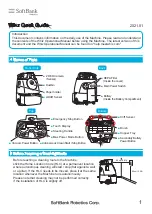
Whiz
Brand: SoftBank Pages: 4

WeeeBot Extended Form B
Brand: WEEEMAKE Pages: 10

Mousr
Brand: Petronics Pages: 24


