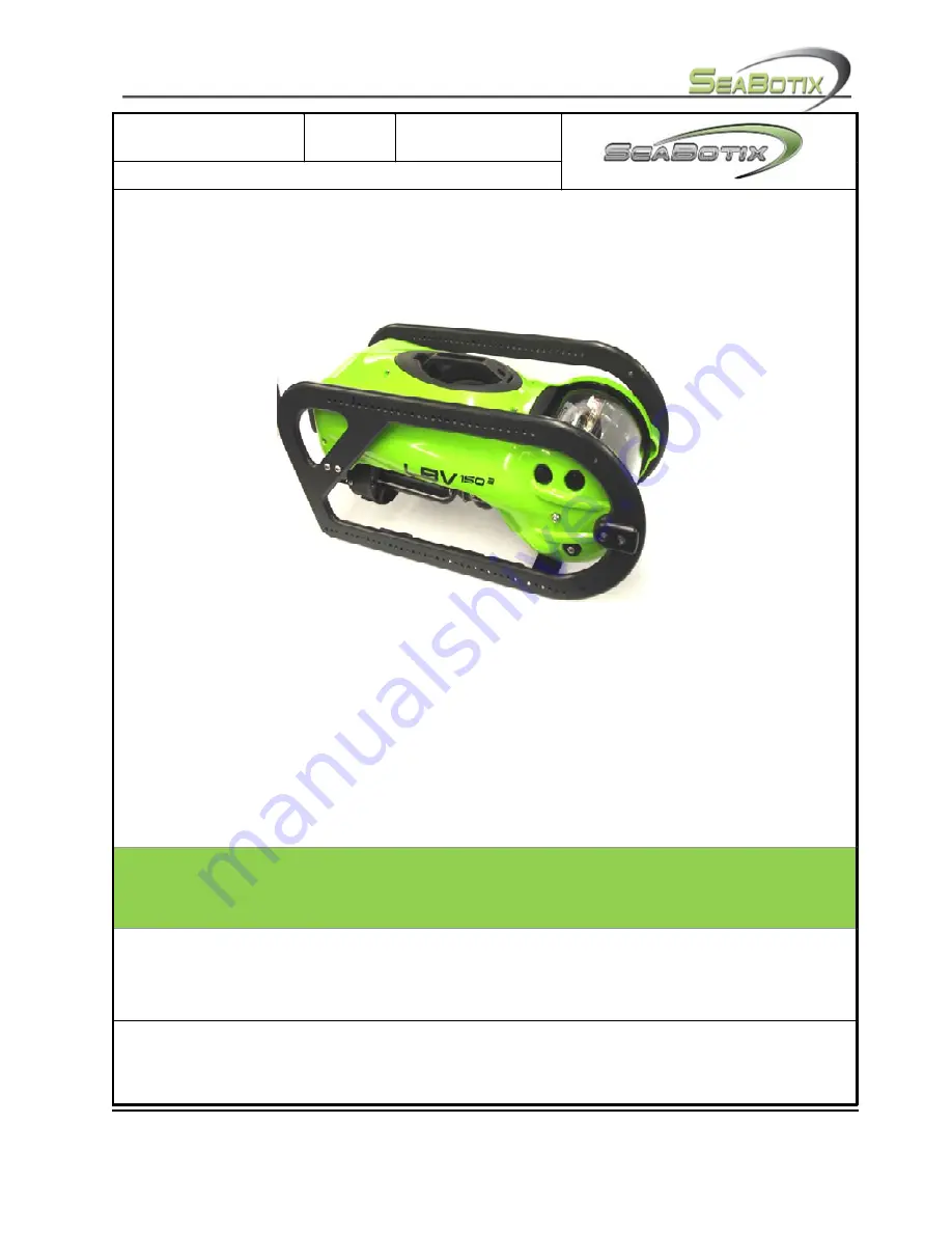
background image


Title: 

LBV150 

Revision:  

Revision Date:  

27 Jan 10 

Document Number:


DOCS-


001  


©2009 SeaBotix Inc., all rights reserved 


User’s


Manual


Proprietary


Notice:


Words


and


logos


marked


with


®


or


are


registered


trademarks


or


trademarks


of


their


respective


owners.


No


license


under


any


copyright,


trademark,


patent


or


other


intellectual


property


right


of


SeaBotix


or


any


third


party


are


granted


by


implication


in


connection


therewith.


This


Document


is


being


furnished


in


confidence


by


SeaBotix


Inc.


This


Document


and


the


information


disclosed


herein


are


proprietary


data


of


SeaBotix


Inc.


Neither


this


Document


nor


the


information


contained


within


shall


be


used,


reproduced,


or


disclosed


to


third


parties


without


the


express


written


authorization


of


SeaBotix


Inc.


Use


of


this


Document


for


other


than


the


intended


purpose


is


strictly


prohibited.


Head Office

: SeaBotix Inc., 2877 Historic Decatur Road STE 100, San Diego, CA 92106 USA +1 (619) 450-4000 

Australia Office

: SeaBotix Australia Pty Ltd.8A Sparks Road, Henderson, WA 6166, Aus61 (0)8 9437-5400


Summary of Contents for LBV150

Page 1: ...th This Document is being furnished in confidence by SeaBotix Inc This Document and the information disclosed herein are proprietary data of SeaBotix Inc Neither this Document nor the information contained within shall be used reproduced or disclosed to third parties without the express written authorization of SeaBotix Inc Use of this Document for other than the intended purpose is strictly prohi...

Page 2: ... Unpacking System 10 1 2 Power Requirements 11 1 3 Setting up System 11 1 3 1 LBV 11 1 3 2 Integrated Control Console 13 1 4 Pre Dive Inspection and System Test 13 1 4 1 Inspection 14 1 4 2 Powering up the system 15 1 4 3 Testing system 15 1 4 3 1 Thrusters 15 1 4 3 2 Camera s 16 1 4 3 3 Video Overlay 16 1 4 3 4 Accessories 16 1 5 Post Dive Inspection 17 1 6 Storage of System 17 1 7 Trimming ROV 1...

Page 3: ...s counter 25 2 2 1 5 Depth 25 2 2 1 6 Camera Angle 26 2 2 1 7 Temperature 26 2 2 1 8 Time 26 2 2 1 9 Date 26 2 2 2 0 User Text 26 2 3 MENUS 27 2 3 1 Quick Menu 27 2 3 2 Main Menu 27 2 3 3 Setup Menu 28 2 3 4 Calibrate Menu 29 2 3 5 Diagnostics Menu 31 2 3 6 Options Menu 31 Section 3 Operating the LBV 33 3 1 Operating Environment 33 3 2 Deployment 33 3 3 Tether 33 3 4 Piloting 33 3 5 Practice 34 3 ...

Page 4: ...al Components 44 Section 5 Troubleshooting 45 5 1 Introduction 45 5 2 Brief Theory of Operation 45 5 3 Troubleshooting Aids 46 5 4 Proper Operating Conditions 47 5 5 Failure Modes 48 Glossary of Abbreviations 51 Sales Terms and Conditions 24 Month Limited Warranty 54 Limitations and Exclusions 61 Shipping and Return Material Authorization RMA Forms 61 Allocation of Risks 62 APPENDIX BY ALPHABET 63...

Page 5: ...pplicable safety messages There are potential safety hazards associated with the operating environment and with the operation of this equipment SeaBotix Inc will not be held liable for negligent or unsafe operation It is your responsibility to make this document available to others that will operate or maintain this product Purpose of this manual The purpose of this manual is to provide LBV operat...

Page 6: ...f SeaBotix Inc or any third party are granted by implication in connection therewith This document is being furnished in confidence by SeaBotix Inc This document and the information disclosed herein are proprietary data of SeaBotix Inc Neither this document nor the information contained within shall be used reproduced or disclosed to third parties without the express prior written authorization of...

Page 7: ... Nothing in this document is intended to supersede applicable local state country federal etc laws regulations and standards or as directed by the Governing Regulatory Body In the event of conflict between this document and applicable legislative requirements the legislative requirements shall prevail General Safety Overview This section and the safety messages throughout this document is intended...

Page 8: ...that safe work conditions exist that they are working in a safe manner and to anticipate any potential risks If an unsafe or potentially unsafe condition exists stop work immediately until the unsafe condition is corrected Whenever there is any doubt always err of the side of caution and stop work until it has been positively determined that it is safe to continue working Anyone who uses a service...

Page 9: ...the tether is cut chafed or otherwise damaged do not operate the LBV Do not open the LBV housing when the power is on Testing Each LBV system is carefully manufactured to ensure long term safe operation Prior to shipment every LBV is tested for proper operation including pressure testing to full operating depth Should a defect be found contact SeaBotix Inc or an authorized distributor immediately ...

Page 10: ...d from harsh conditions and clear of potential hazards Requirements for operation Suitable power source Dry area Contents of packaging LBV underwater vehicle Integrated Control Console Tether and or Tether reel Spares Tool Kit Manual CD ROM Accessories if applicable Note When unpacking the LBV after receipt inspect the LBV for damage It is strongly recommended that vacuum be verified before each u...

Page 11: ...hat is configured to 100 130 VAC into 200 250 VAC or vice versa This will damage the LBV system and may cause physical harm LBV systems fitted with the HPDC1502 Brushless DC Thrusters have a requirement for 1200 watts at 100 130 200 250 VAC 50 60 Hz 1 3 Setting up System Select a suitable area from which the LBV will be deployed and controlled The area should be dry and not in direct sunlight Now ...

Page 12: ...ocking rod to be flush with the D portion of the shackle Step 6 ALWAYS ATTACH THE SHACKLE PRIOR TO ATTACHING THE TETHER Slide the shackle over the pad eye on the flotation module Twist the locking rod to secure Step 7 Push the female connector onto the male bulkhead connector being careful to align the pins There is a single small pin used for alignment Step 8 Tighten the locking sleeve clockwise ...

Page 13: ... the LBV 5 There is an RS 232 connector which is used for flashing the LBV SONAR interface and or tracking responder triggering 1 Circuit Breaker 2 Red LED POWER 3 Amber LED STATUS 4 Video In 5 AUX Video Out 6 RS232 Connector 7 Tether Whip Connection 8 Power Input Connection NOTE Make sure that there is no water or debris on or in the connectors prior to connecting 1 4 Pre Dive Inspection and Syst...

Page 14: ...he propellers 4 Check the vacuum before every dive The following page outlines the procedure for performing a vacuum seal check on the primary LBV housing Step 1 Place the LBV on a table with the vacuum check valve facing you Step 2 Remove the Phillips pan head seal screw from the vacuum valve Step 3 Connect the vacuum hose and ensure that the fitting is tight Step 4 Pull vacuum to 10 inches of me...

Page 15: ... Power Supply should begin to strobe 2 seconds on off c The camera video should come up on the monitor with Video Overlay 3 The 12 VDC 5 VDC LED s on the Motherboard should illuminate 4 The Data In Out LED s on the Motherboard should flash at a 2 Hz twice per second rate 5 The Power LED red on the sensor board should illuminate 6 The status LED amber on the sensor board should strobe 2 seconds on ...

Page 16: ...tional second camera if fitted a Test FOCUS and FOCUS on the second camera if fitted NOTE The FOCUS function will not operate on a rear facing camera 4 Push the LIGHT key to turn on the internal light 5 Push and to vary the light intensity a Repeat with the second camera if fitted NOTE Do not leave the light on for more than a few seconds when the LBV is out of the water Leaving the light on may c...

Page 17: ...all cables and store If the LBV is equipped with an ICC place the operator control unit face down in its storage tray Place the Surface Power Supply in a carrying shipping case Place the operator control unit in a carrying shipping case Coil the tether as described in Tether section page 30 section 3 3 Place the tether in a carrying shipping case Close and clamp cases closed for transport or stora...

Page 18: ...ps and attach to the lower portion of the bumper frame using M5x10 button head screws Be sure to place in the same relative position to ensure that the LBV is properly set up left to right and fore to aft 1 8 Calibrating Compass The LBV is fitted with a magnetic compass that is designed to provide basic heading data It should be noted that the sensor is fixed inside the LBV and therefore is suscep...

Page 19: ... key to successful calibration is that the LBV is level and rotated as slowly as possible This may take several minutes but ensures the most accurate reading Once complete Press ENT Press PGRM NOTE This calibration is required initially and is then stored into memory however should the LBV be used in a different geographic location re calibration may be required It is good practice to calibrate th...

Page 20: ... the vertical thruster knob Place the right hand in such a way that the forefinger and thumb holds the top of the joystick and the other three fingers support the console Some may prefer to place the console on a flat surface 2 1 1 Joystick Pushing the joystick forward moves the LBV in the forward direction Pulling the joystick backwards moves the LBV in the reverse direction Moving the joystick l...

Page 21: ...ock the thruster settings without having to manually hold a key or move the joystick For example a user wishing to maintain a heading and speed need only hold the joystick producing the desired vector while depressing the TRIM button once Press the TRIM button again to regain control Vertical trim is accomplished with the vertical thruster knob TRIM on and off is displayed on the Video Overlay 2 1...

Page 22: ...r down The maximum rotation is 180 degrees per camera giving a total of 270 degrees if an optional second camera is fitted As the camera chassis rotates the angle is displayed on the Video Overlay Note In the options menu the keys can be reversed for the desired preference See Options Menu section page 29 section 2 3 6 3 2 1 10 FOCUS The FOCUS buttons allow the user to focus the cameras Pressing t...

Page 23: ...ection 2 2 2 1 14 ACCESSORIES If optional accessories are fitted such as a grabber the and the keys allow the user to activate the accessory For the grabber the opens and the closes the jaws 2 1 15 KEYPAD The KEYPAD offers a variety of functions When adjusting the gain control for the thrusters the numbers are used to select the percentage of power available The keypad is used to input alphanumeri...

Page 24: ...position and orientation The Video Overlay can be manipulated to display the information how it best suits the user Video Overlay 1 User Text 7 Date 2 Vertical thruster GAIN 8 Horizontal Thruster GAIN 3 Internal Light Trim Function 9 Selected Accessory 4 Heading 10 Depth Reference 5 Turns Counter 11 Temperature Reference 6 Camera Angle 12 Time 4 2 3 5 6 7 8 9 10 11 12 User text here 1 ...

Page 25: ...splay will alternate between TRM and L 2 2 1 3 Heading Heading is displayed at the top middle of the Video Overlay 4 The three digits illustrate the 360 degrees of a compass heading To the right of heading is a or a 2 2 1 4 Turns counter This is the turns counter which represents the number of turns the LBV makes in one direction of 360º 5 The indicates turns in the clockwise direction and the ind...

Page 26: ... is derived from an onboard sensor which detects both water and air temperature depending on the medium This value can be displayed in either centigrade or Fahrenheit To change the setting or calibrate the temperature see the Menu section page 28 section 2 3 4 2 2 2 1 8 Time At the right of the display is the time 12 This information is preset at the factory and can easily be changed to the time z...

Page 27: ...ional accessory Same as 1 3 Acc Not Found a Pressing the 3 key will enable the Accessory and keys to operate an optional accessory Same as 1 and 2 4 Acc Not Found a Pressing the 4 key will enable the Accessory and keys to operate an optional accessory Same as 1 and 2 5 Acc Not found a Pressing the 5 key will take you to the Main Menu 2 3 2 Main Menu The main menu is the starting point for customiz...

Page 28: ...the month is March press 0 then 3 4 Press ENT 5 Select the year by using the keypad 6 Press ENT 7 Enter the hour of the day in 24 hour time by using the keypad 8 Press ENT 9 Enter the minute of the hour by using the keypad 10 Press ENT 11 Enter the second of the minute by using the keypad 12 Press ENT 2 Units Water Type a Pressing the 2 key will allow you to adjust the type of measurement being us...

Page 29: ...t 1 Press 5 three 3 times until the L is shown 2 Press ENT 3 Press 2 two 2 times until the B is shown 4 Press ENT 5 Press 8 three 3 times until the V is shown 6 Press 0 two 2 times 7 Press ENT 8 Press 1 one 1 time 9 Press ENT 10 Press 5 four 4 times 11 Press ENT 12 Press 0 one 1 time 13 Press 14 Press PRGM 5 Reset to Defaults a Pressing the 5 key will reset the entire LBV to factory settings 2 3 4...

Page 30: ... the value Press key 2 to decrease the value Press key 3 to set to zero Press key 4 to reset to default Press key 5 to set the slope 4 Compass Heading a Pressing the 4 key will allow you to calibrate the compass heading information on the Video Overlay To calibrate the compass refer to page 14 section 1 8 Calibrating Compass for more information 5 Monitor a Pressing the 5 key will allow you to adj...

Page 31: ...BV has been powered up 4 Display Ext Temp a Pressing the 4 key will display the internal temperature of the LBV where the external temperature is normally displayed When you exit the menu the temperature reading resets to the external temperature 2 3 6 Options Menu 1 Camera Rotate a Pressing the 1 key will allow you to turn camera rotate on and off Camera rotate allows the user to select how the c...

Page 32: ...of the camera tilt keys 4 Vertical Thrust a Pressing the 1 key will reverse the operation of the vertical thruster control knob Rotate forward will now dive the LBV Rotation aft will surface the LBV NOTE The internal microphone is not available in all models If your LBV is equipped with Fiber Optic Video the internal microphone is not available ...

Page 33: ... out 3 3 Tether A key feature to the LBV performance is the small diameter tether By reducing the size of the tether drag is greatly reduced thus enabling the LBV to operate in strong currents or with long lengths of cable in the water Because of its small size and light weight managing the tether is simple The tether is neutrally buoyant in fresh water and slightly positively buoyant in sea water...

Page 34: ...ing depth gain control time date temperature and more Turns counter Keeps track of how many turns in the tether to avoid entanglement 270 Degree field of vision Allows the operator to view straight up or straight down movement on the Video Overlay Rotating light Illuminates where the camera is looking User text Used to keep track of information for review at a later date 3 5 Practice Before using ...

Page 35: ...r that is comfortable to you The most common way is with the left hand supporting the left side of the controller with your thumb on the vertical thruster knob Use your right hand to hold the right side with your fore finger and thumb holding the top of the joystick Consider these points Move the joystick with a smooth motion Do not over steer Adjust the thruster gain to suit conditions lower gain...

Page 36: ...are just as they sound By pressing either of the keys the LBV will hold depth or maintain heading A green LED above each key will illuminate to show that the auto function is on An important item to remember is that for this function to operate correctly the LBV must be on a stable heading and or at depth when the function is selected Auto Depth When a desired depth is obtained press the Auto Dept...

Page 37: ...e that may have occurred during use If used in sea water wash the LBV thoroughly with fresh water It is recommended that the LBV be submerged in a container filled with fresh water Let as much water drip off of the LBV as possible Place the LBV in its protective carrying case Wash the tether with fresh water Coil the tether for storage 4 1 1 After each use dirty water conditions If the LBV is oper...

Page 38: ...aid to any cabling exiting the camera chassis Placing stress on these cables can damage the cable and or the water tight integrity of the LBV itself Step 5 Remove the four M6 x button head screws securing the bumper frame to the shell TO005 required Step 6 Fasteners removed 1 ea Lead Trim Weight if installed 2 ea M4 X 20 Button Head Screws 2 ea M4 X 25 Button Head Screws Step 7 Remove the two M5 x...

Page 39: ...tep 11 Fasteners removed 1 ea Lead Trim Weight if installed 2 ea M4 X 20 Button Head Screws 2 ea M4 X 25 Button Head Screws Step 12 If a grabber is installed disconnect the grabber at this time Now remove the bumper frame with the crossbar still attached Step 13 Remove the M6 Nyloc nut securing the front of the shell to the camera housing end cap TO012 Required Step 14 Remove the M4 x 50 Phillips ...

Page 40: ...llips 1 ea 44 6mm Spacer 1 ea M6 Nylock Nut Step 19 Turn the LBV over Remove the M6 Nyloc nut securing the front of the shell to the camera housing end cap TO012 Required Step 20 Remove the M4 x 10 Phillips head screw securing the rear portion of the shell to the float TO015 Required Step 21 Remove the 2 M4 x 20 Phillips head screws securing the shell to the float TO015 Required Step 22 Fasteners ...

Page 41: ... 2 Every 50 hours Every 50 hours of operation require that you push new grease GLA003 which is supplied with your order into the grease galley on each of the 4 thrusters The procedure is very simple and will only take approximately 25 minutes to complete Step 1 Follow procedure 4 1 1 removing the bumper frame and shell Steps 1 to 17 Step 2 Place the LBV upside down Step 3 Remove the trim tab Step ...

Page 42: ...head screws securing the forward Kort nozzles to the port and starboard thruster assemblies and the 2 screws securing the thruster hold down tabs then remove the Kort nozzles Step 9 Remove the 3 Phillips head screws securing the lateral Kort nozzle to the lateral thruster and remove the Kort nozzle Step 10 Remove the black plastic Phillips head screw at the propeller end of each thruster end cap F...

Page 43: ... hours After operating the LBV for 500 hours it is recommended that the seals be replaced throughout the LBV including the thrusters Contact SeaBotix Inc or your nearest authorized repair distributor 4 3 Long term There is little need for long term maintenance as long as the LBV is taken care of and the 500 hour maintenance is performed There may be a need to replace the view port if it is scratch...

Page 44: ...re LBV software is continually refined and updated Updates are available on www seabotix com including the correct procedure for updating the software NOTE Contact service seabotix com with your LBV serial number prior to installing any software updates for assistance in determining the correct revision for your LBV 4 6 Optional Components If your LBV is fitted with optional equipment refer to the...

Page 45: ...vailable power since plugging into the wrong supply could damage your LBV Whenever the LBV system is used the Surface Power Supply must be plugged into a grounded outlet Failure to use a grounded outlet will disable the GFI circuitry as well as cause possible communication and LBV control problems On most LBVs PAL or NTSC the video output is broadcast channel 3 This means that your video monitorin...

Page 46: ...he Surface Power Supply is coupled onto the 360 VDC power lines and is transmitted to and from the LBV Within the LBV communication is controlled by the Motherboard which effectively addresses each modular component For example port thruster sensor board external light tilt motor etc 5 3 Troubleshooting Aids The following pictures show various components of the LBV system Please refer to these whe...

Page 47: ...ever the term normal is used in the Troubleshooting Guide it refers to the proper operating condition of that device or indicator After correctly connecting all the LBV components indications of the normal operating condition of the LBV system is as follows Upon energizing the SPS main power switch the SPS red and amber LEDs are continuously lit and do not flash The LBV is not energized and the LB...

Page 48: ... close grabber etc 5 5 Failure Modes Symptom No video and no LBV control This mode is usually accompanied by alternate flashing of the CC Auto head and depth LEDs OCU power LED is lit Fault The SPS is not supplying 360 VDC Cause GFI has been tripped due to an insulation failure in the SPS tether or LBV The SPS amber LED flashes one long pulse and two short pulses All Motherboard LEDs are unlit Fau...

Page 49: ...se One or more external LBV component has a short between 28 VDC and ground Fault Isolation Following the procedure manual remove one backplane component at a time re energizing the LBV each time to test for normal operation of the remaining components Be advised that though all thrusters are modular and interchangeable the port and starboard thrusters operate in concert So if no thrusters operate...

Page 50: ...e failure is in the forward or aft direction For example If the failure occurred in the forward direction you can determine which thruster failed by utilizing the LBV s rotate function Rotating the LBV clockwise causes the port thruster to thrust forward while the starboard is thrusting aft By using this feature the troubleshooter can run each thruster in one direction at a time The faulty thruste...

Page 51: ...lable as a composite signal at the MUX hub of the tether reel system FSK Frequency Shift Keying A method of data transmission utilizing 2 5 channels of RS232 format for command and control of the LBV data transmission to an external RS232 device with a remaining simplex channel for data to a device attached to the LBV GAK Grabber Attachment Kit Hardware All hardware descriptions prefixed with the ...

Page 52: ...urface Power Supply PCA Printed Circuit Card Assembly PIC Programmable IC Used extensively on the circuit boards to pre program them for functions as required POH Pull Out multiplexer Hub Part of the URS It contains the MUX as well as the termination point for the tether and the tether whip PSI Power Supply Interface circuit board part of the VPS QRS Quick Recovery System A secondary manual system...

Page 53: ...ecovery of the LBV system UMB Tether Note Historically the term umbilical was used hence the UMB in the reference to the part numbers Going forward umbilical is now referred to as tether Example In deep water applications where the LBV is flown from another larger ROV or TMS Tether Management System an umbilical is the line that leads from the topside handling system to the larger ROV or TMS URS U...

Page 54: ...auses or requests a shipment delay or if SeaBotix ships or delivers the products erroneously as a result of inaccurate incomplete or misleading information supplied by Customer or its agents or employees storage and all other additional costs and risks shall be borne solely by Customer Claims for products damaged or lost in transit should be made by Customer to the carrier as SeaBotix s responsibi...

Page 55: ... decline to make any shipments or perform any work except upon receipt of payment or terms and conditions satisfactory to SeaBotix If in the judgment of SeaBotix the financial condition of Customer at any time does not justify continuation of production or shipment on the terms of payment originally specified SeaBotix may require full or partial payment in advance In the event of a Default by Cust...

Page 56: ...he insuring party SeaBotix shall charge the Customer an insurance fee based upon the value of the products in storage d DELIVERY Customer shall provide instructions for final delivery of the products or indicate that it will accept delivery itself including a delivery date in the written request for Bill and Hold Consistent with shipment FOB shipping point Customer bears all risks and responsibili...

Page 57: ... the installation and or use of the products SeaBotix makes no promise or representation that the products or services will conform to any federal state or local laws ordinances regulations codes or standards except as particularly specified and agreed upon in writing by an authorized representative of SeaBotix SeaBotix shall not be responsible for any losses or damages sustained by the Customer o...

Page 58: ...a product in a specification sheet and the product that is shipped to Customer Customer may return products in accordance with SeaBotix standard return policies in effect on the date of the invoice Any and all returns must be pre authorized by SeaBotix All goods should be inspected upon delivery and any defects nonconformance or rejection reported to SeaBotix within twenty one 21 days of shipment ...

Page 59: ...osure using the name of SeaBotix without prior written approval 21 WAIVER The failure of SeaBotix to insist on the performance of any obligation of Customer hereunder shall not be construed as a waiver by SeaBotix of such obligations or any other obligation of Customer hereunder and the same shall remain an obligation of Customer 22 SOLICITATION OF SEABOTIX REPRESENTATIVES Customer agrees that it ...

Page 60: ... the entire understanding of the parties as to the subject matter hereof and supersedes all prior or contemporaneous agreements written or oral as to such subject matter No employee of SeaBotix or any other party is authorized to make any warranty in addition to those made herein THIS WARRANTY IS EXPRESSLY IN LIEU OF ANY OTHER WARRANTIES EXPRESSED OR IMPLIED INCLUDING ANY IMPLIED WARRANTY OF MERCH...

Page 61: ... party warranties SeaBotix will lend assistance to OWNER when required to facilitate the performance of third party warranties but bears no responsibility for such third party s performance THE REMEDIES SET FORTH HEREIN ARE OWNER S EXCLUSIVE REMEDIES FOR BREACH OF WARRANTY Shipping and Return Material Authorization RMA Forms Immediately upon identifying a problem which you believe to be subject to...

Page 62: ...ely responsible for the cost of shipping to and from the authorized SeaBotix Warranty Center Contact SeaBotix for your closest Warranty Center to help reduce the distance the GOODS must be delivered In all cases the OWNER bears all risk of loss related to the GOODS during shipment and should consider insuring the shipment both to and from SeaBotix If SeaBotix is unable to repair the GOODS to confo...

Page 63: ... Angle 24 Controlling LBV 32 Date 25 Deployment 30 Depth 24 Diagnostics Menu 29 Every 50 hours 37 Every 500 hours 39 Failure Modes 43 Focus 21 Gain Control 23 Glossary of Abbreviations 46 Heading 24 Horiz Gain 20 Inspection 14 Integrated control console 13 Introduction 10 Joystick 19 Keypad 22 LBV 11 Light 21 Light Level Indicator 24 Limitations 34 Long term 39 Main Menu 26 MENUS 25 Operating Envi...

Page 64: ...uick Menu 25 Repairs 39 Return Policy 49 Setting up System 11 Setup Menu 26 Shipping Charges 49 Software 39 Storage of System 17 Temperature 25 Testing of System 15 Tether 30 Thruster Gain Control 23 33 Thrusters 15 Tilt 21 Time 25 Trim 33 Trim 24 Trimming ROV 17 Troubleshooting Aids 41 Turns counter 24 Unpacking System 10 User Text 25 Vertical Gain 20 Video Overlay 16 Video Overlay 22 Video Overl...

Reviews: