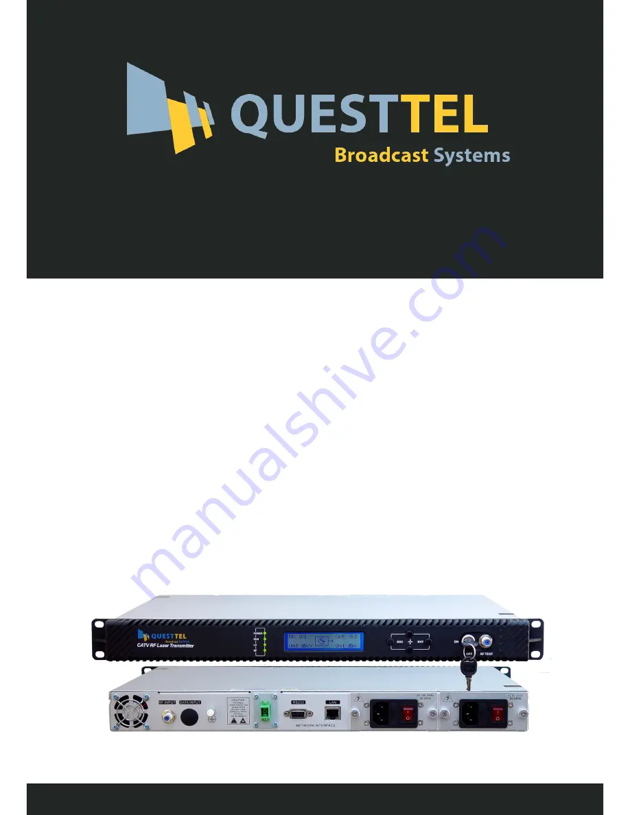
background image

User 

Manual

CATV 

32

 mW RF Optical 

Transmitter 47-750/862/1003 MHz

 L-RF-32mW-TX

www.questtel.com

[email protected]

Summary of Contents for L-RF-32mW-TX

Page 1: ...User Manual CATV 32 mW RF Optical Transmitter 47 750 862 1003 MHz L RF 32mW TX www questtel com sales questtel com...

Page 2: ...hile the optical transmitter is working there is an invisible laser beam from the optical output adapter on the front panel Avoiding permanent harm to the body and eye the optical output should not ai...

Page 3: ...ccording to the RF input signal level and the number of channels 15 84 channels make the CSO CTB and C N index always at the optimal value to ensure the overall performance Advanced multi frequency RF...

Page 4: ...alog TV channel signal at 750MHz frequency range under the specified link loss When the optical input power of optical receiver is 1dBm measure the C CTB C CSO and C N 4 2 Technique Parameters Table I...

Page 5: ...gradation table Optical power Optical link loss dB 4 5 6 7 8 9 10 11 12 13 14 15 16 17 18 4mW 53 8 52 8 51 8 51 50 1 49 2 48 2 6mW 53 0 52 0 51 0 50 1 49 1 48 1 8mW 52 8 51 9 51 0 50 1 49 2 48 2 10mW...

Page 6: ...eans the RF input signal is warned green light means RF input signal is normal 5 160 32 dot matrix LCD screen used to display all the parameters of the machine 6 Display the exit or cancel key of the...

Page 7: ...output port of the device The connector type is FC APC There is an invisible laser beam from this port while working normal So the port should not be aligned to human body or naked eye to avoid accid...

Page 8: ...ress Enter key into the menu index 1 Parameter menu 2 Set parameters 3 Alarm menu 5 Sub menu of parameters Press Enter key into the menu Content Meaning Optical output power of the laser at present Bi...

Page 9: ...e Switching power supply output 5V supply voltage Switching power supply output 5V supply voltage Switching power supply output 24V supply voltage Serial number Internal temperature at present IP addr...

Page 10: ...GC or MGC Set the attenuation of MGC Set the offset of AGC start control level Set system transmission channels number This parameter is used to correct the accuracy of displayed laser RF signal level...

Page 11: ...t to the rack and reliably grounding The grounding resistance must be 4 3 Use the digital multimeter to check the supply voltage make sure the supply voltage comply with the requirements and the switc...

Page 12: ...tlike curve or large particles highlights 1 The received optical power of the optical contact point is too high the output level of the optical receiver module is too high and intermodulation index of...

Page 13: ...s noises The C N indexes of these channels are too low Check the C N of these channels signal and make appropriate adjustments After initial startup the image of several optical contact points appear...

Page 14: ...ptical power is on the low side after clean the adapter may be polluted clean it Note Adapter should be carefully operated so as to avoid hurting inside fiber 6 Use compressed air or degrease alcohol...

Page 15: ...ck 7 Object and Liquid Entry Never push objects of any kind into this product through openings as they may touch dangerous voltage points or short out parts resulting in a fire or electric shock Never...

Reviews: