


PRONAR Sp. z o.o.
17-210 NAREW, UL. MICKIEWICZA 101A, PODLASKIE PROVINCE
tel.:
+48 085 681 63 29
+48 085 681 64 29
+48 085 681 63 81
+48 085 681 63 82
fax:
+48 085 681 63 83
+48 085 682 71 10
www.pronar.pl
OPERATOR’S MANUAL
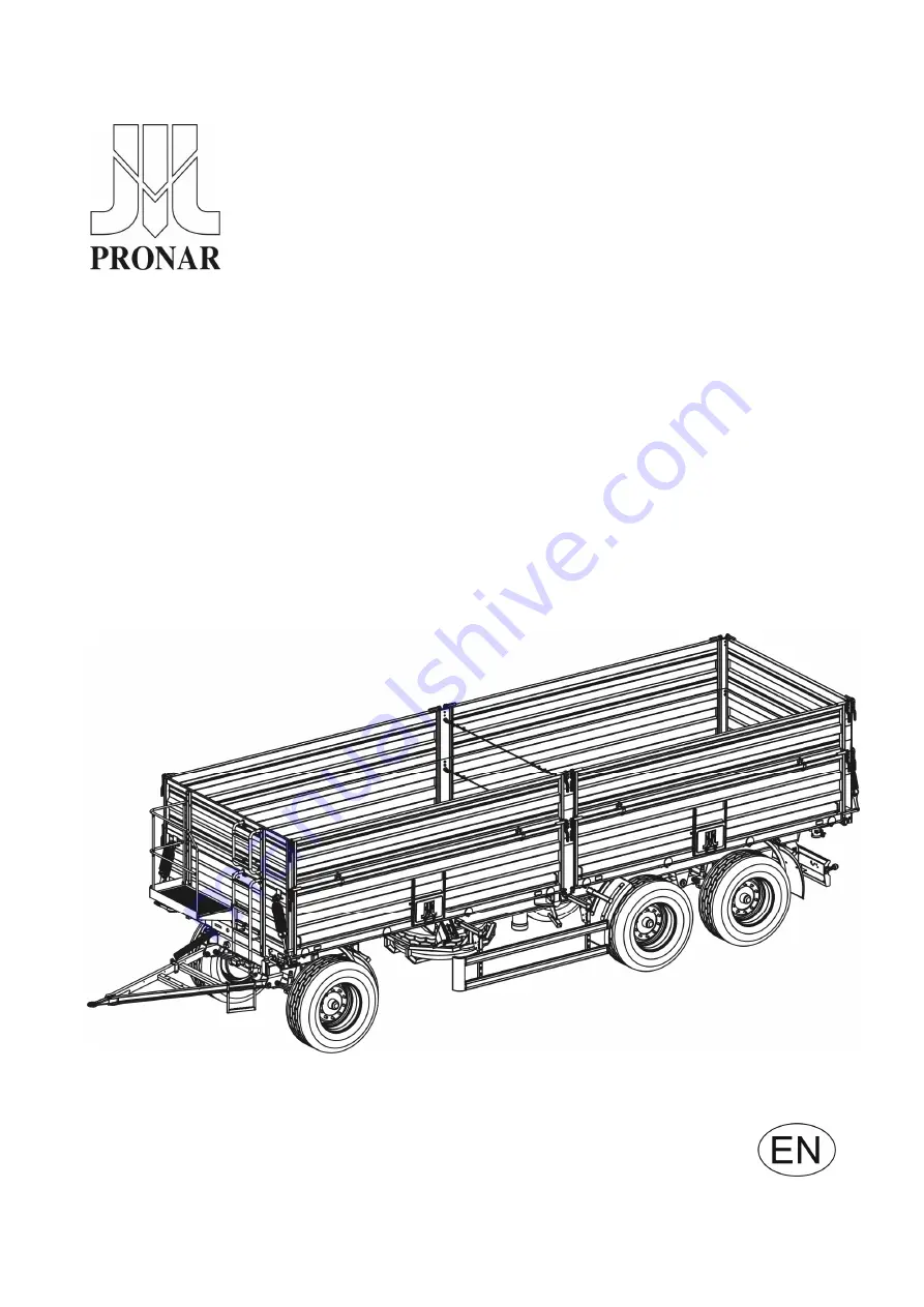
TRAILER
PRONAR T780
Translation of the original instructions
ISSUE 3B-01-2010
PUBLICATION NO 163N-00000000-UM
Summary of Contents for T780
Page 2: ......
Page 5: ......
Page 17: ...1 10 ...
Page 43: ...3 14 ...
Page 72: ...5 13 DRAWING 5 6A CHASSIS GREASING POINTS ...
Page 73: ...5 14 DRAWING 5 7A LOAD BOX GREASING POINTS ...
Page 80: ...5 21 ...
Page 81: ...NOTES ...
Page 82: ... ...


