


PRONAR Sp. z o.o.
17-210 NAREW, UL. MICKIEWICZA 101A, WOJ. PODLASKIE, POLAND
Phone.:
+48 085 681 63 29
+48 085 681 64 29
+48 085 681 63 81
+48 085 681 63 82
Fax:
+48 085 681 63 83
+48 085 682 71 10
www.pronar.pl
OPERATOR'S MANUAL
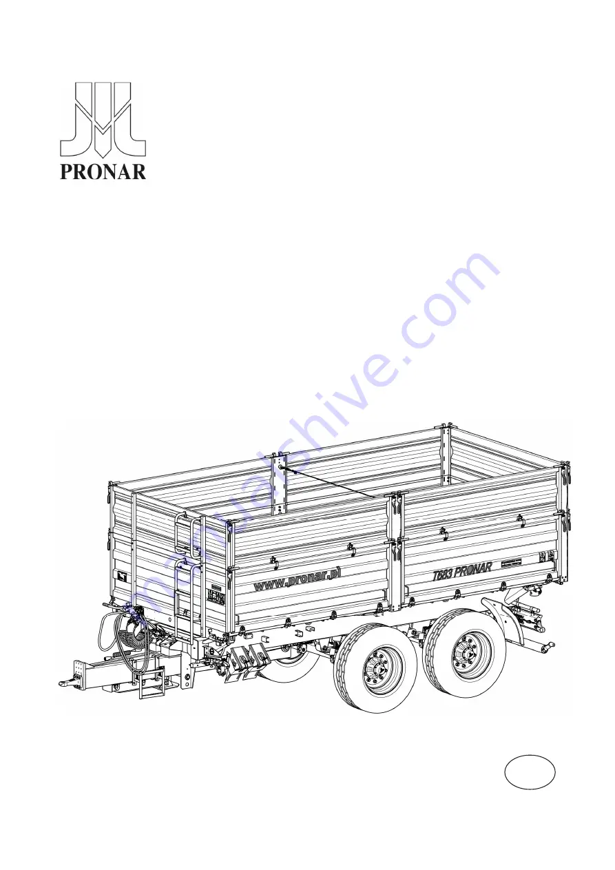
TRAILER
PRONAR T683
TRANSLATION OF THE ORIGINAL DOCUMENT
ISSUE 1A-03-2015
PUBLICATION NO. 511N-00000000-UM
EN
Summary of Contents for T683
Page 2: ......
Page 6: ......
Page 11: ...SECTION 1 BASIC INFORMATION ...
Page 26: ...Pronar T683 SECTION 1 1 16 ...
Page 27: ...SECTION 2 SAFETY ADVICE ...
Page 45: ...SECTION 2 Pronar T683 2 19 FIGURE 2 3 Locations of information and warning decals ...
Page 46: ...Pronar T683 SECTION 2 2 20 ...
Page 47: ...SECTION 3 DESIGN AND OPERATION ...
Page 73: ...SECTION 4 CORRECT USE ...
Page 103: ...SECTION 5 MAINTENANCE ...
Page 133: ...SECTION 5 Pronar T683 5 31 FIGURE 5 13 Trailer s lubrication points part 1 ...
Page 134: ...Pronar T683 SECTION 5 5 32 FIGURE 5 14 Trailer s lubrication points part 2 ...
Page 145: ...NOTES ...
Page 146: ... ...


