


T h e B e s t W a y
T o G o
A b o u t Y o u r
B u s i n e s s
TAYLOR-DUN
N
®
READ THE OPERATOR’S MANUAL BEFORE OPERATING
THIS VEHICLE.
The operator’s manual contains important information
regarding the safe operation of this vehicle.
WARNING
Starting Serial Number: 207800
Ending Serial Number: See Introduction Chapter
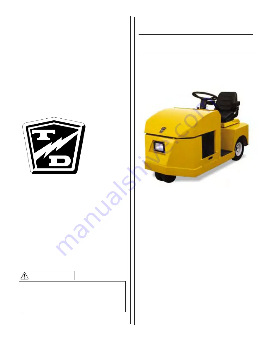
Service and Replacement
Parts Manual
MANUAL: ME-455-04
E-455
Model Numbers:
E0-455-24
E0-455-36
D
Summary of Contents for E0-455-24
Page 6: ......
Page 12: ...Page 12 ME 455 04 Introduction E 455 Notes ...
Page 27: ...Lubrication Page 27 ME 455 04 E 455 LUBRICATION DIAGRAM GT Transaxle SD Transaxle ...
Page 28: ...Lubrication Page 28 E 455 ME 455 04 Notes ...
Page 49: ...Transaxle Page 49 ME 455 04 E 455 ...
Page 58: ...Steering Page 58 E 455 ME 455 04 Exploded View of Steering Gear ...
Page 68: ...Brakes Page 68 E 455 ME 455 04 Notes ...
Page 94: ...Suspension Page 94 E 455 ME 455 04 Notes ...
Page 106: ...Replacement Parts Page 106 ME 455 04 E 455 GT TRANSAXLE ASSEMBLY REAR ...
Page 110: ...Replacement Parts Page 110 ME 455 04 E 455 BATTERY ...
Page 132: ...Replacement Parts Page 132 ME 455 04 E 455 Notes ...
Page 133: ......


