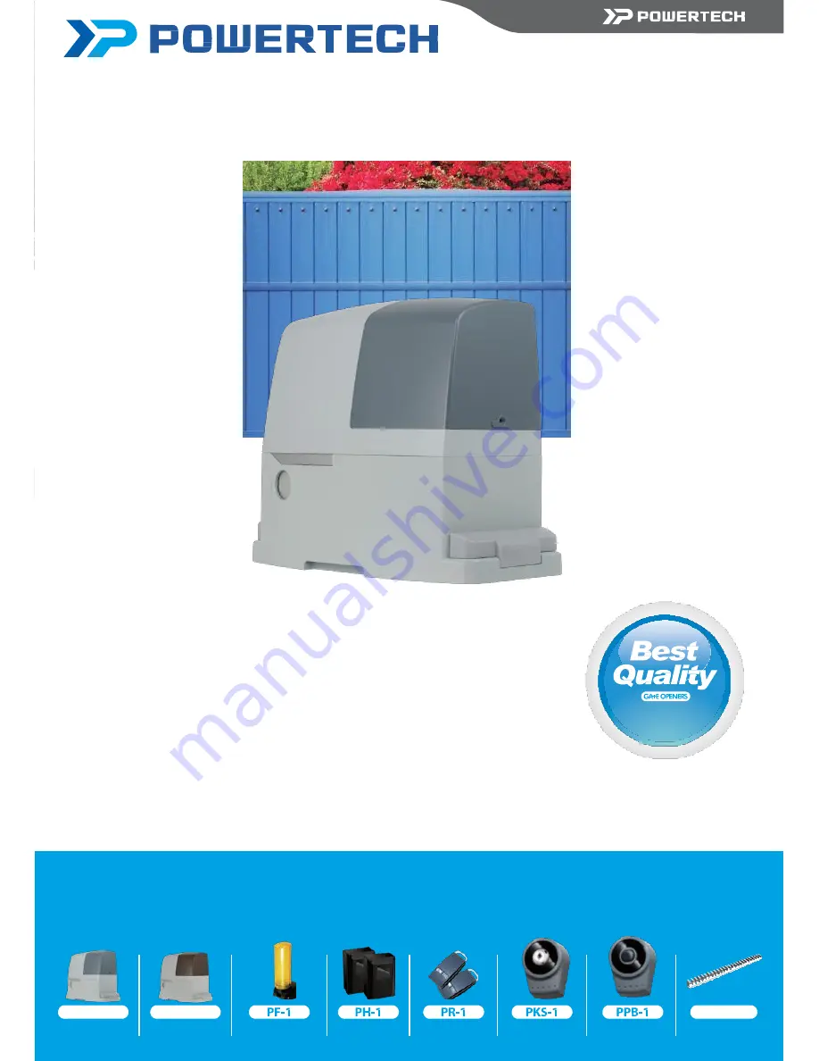
background image


SLIDING GATE OPENER


DESIGNED FOR RESIDENTIAL APPLICATION


KIT 

PL600/PL1000


SLIDING GATE OPENERS


PL600/PL1000 electro-mechanical sliding gate openers are designed for residential application.


The strongest solution 

for sliding gates


Stylish appearance of the gear motors with innovative design of motor release by the key in case of power failure. 
Magnetic limit switch and spring limit switch are available for customer’s choice.


Over-current function with adjustable setting provides various choices for the gate installation.


KIT 

PL600/PL1000


PL600


Gear Motor


PL1000


Gear Motor


Flashing Light 

Photocells 

Transmitter 

Key Selector 

Push Button


PRK-1


Rack


Summary of Contents for KIT PL1000

Page 1: ...gates Stylish appearance of the gear motors with innovative design of motor release by the key in case of power failure Magnetic limit switch and spring limit switch are available for customer s choice Over current function with adjustable setting provides various choices for the gate installation KITPL600 PL1000 PL600 Gear Motor PL1000 Gear Motor Flashing Light Photocells Transmitter Key Selector...

Page 2: ......

Page 3: ...ustration 6 3 2 Power Connection 6 3 2 1 Notes for Power Connection 6 3 3 Preparation for Motor Installation 7 3 3 1 Installation of The Gearmotor 9 3 3 1 1 Installing on Gates without Rack 9 3 3 1 2 Installing on Gates with Rack 11 3 3 2 PH 1 Photocells 12 3 3 3 PF 1 Flashing Light 13 3 3 4 PKS 1 Key selector 14 3 3 5 PPB 1 Push Button 15 3 4 Power Supply Connections 15 4 Final Checks and Start U...

Page 4: ...works properly before installing the gate automated system and confirm the gates are appropriate for the application Do not let children operate or play with the gate automated system Do not cross the path of the gate automated system when operating Please keep all the control devices and any other pulse generator away from children to avoid the gate automated system being activated accidentally D...

Page 5: ...of the Automation The following diagram of PL600 PL1000 typical installation describes some terms live in whereever you are and whenever you are and accessories of a gate automation system G F C C E Figure 1 H I A H 2 3 Description of Devices PL600 PL1000 may include the accessories shown in Figure 2 Please check the accessories the same as the package provided Attention Some accessories of PL600 ...

Page 6: ...ides it has a back up battery optional which can be used during the power failure as well 2 3 2 Release Keys The two keys enable the gearmotor to be released when there is power failure Figure 3 A B E D C F Figure 4 Fuse knob Terminals for devices RF leaning button Digital led display Function setting buttons Back up batteries optional 2 3 2 1 Release Gearmotor 1 Slide the lock cover disc 2 Insert...

Page 7: ...ing Light PF 1 flashing light is controlled by PL600 1000 control unit and blinks when the gate is moving or blinks 3 seconds before the gate moves The flashing light stops blinking when the gates Table 2 List of small parts for PPB 1 Quantity 3 20 Screw 3 pcs Nylon screw anchor 3 pcs 2 3 6 PKS 1 Key selector The PKS 1 key selector is used for opening the gate outdoors without the radio transmitte...

Page 8: ...n The installation procedure of PL600 PL1000 may be changed due to various accessories and quantities installed No wiring cables for accessories are supplied with KIT PL600 PL1000 3 2 Power Connection The users are advised to read the installation manual carefully before going for it After getting to know all accessories and their positions suggest starting from cable conduit arrangement to preven...

Page 9: ...g travel of the gate 4 Make sure the gate is at horizontal level that the gate will not move aside at any position 5 Make sure the gate can bear the impact of the motor torque when it is installed on the plate which the surface is sufficiently sturdy 6 Make sure that the installation area is not easy to be invaded by flood If necessary mount the raised from the ground 7 Make sure the photo sensors...

Page 10: ...ch brackets the rack must project from the axis of the pinion by distances indicated in Figure 14 Left opening and Figure 15 Right opening Figure 14 Left opening 170mm 200mm Figure 15 Right opening 170mm 200mm 11 If the rack is already installed on the gate make sure the position of the rack is fitted for the size limits indicated in Figure16 Figure 16 ...

Page 11: ...n Figure 18 into the foundation and fix them above and below with two nuts as below A Figure 18 part in Figure 18 make sure the outstanding part does not exceed the maximum height as Figure 17 Figure 18 A B 4 Put the foundation plate and make sure the gate keeping the distances shown as Figure 12 5 Fit the conduits through the hole of the foundation plate 6 Pour the concrete 7 Sink the plate into ...

Page 12: ...cks are sufficient for work Figure 21 Figure 22 15 After fixing the last piece cut away the unnecessary parts of racks by a hacksaw if necessary 16 Open and close the gate several times manually and make sure that the rack goes with the pinion smoothly within a maximum tolerance of 5mm 17 Fix the two limit switch brackets with the relative dowels as the E part in Figure 23 Slide the gate in the op...

Page 13: ... Pour the concrete 7 Sink the plate into the concrete and make sure it is parallel to the leaf as below Figure 26 8 After the concrete is dry enough remove the two upper nuts which will no longer be used form the plate and cut the cable conduits above the plate if the conduits are too long 9 Open the cap by the rear of the gearmotor as shown in Figure 27 Figure 26 Figure 27 10 Put the gearmotor on...

Page 14: ... gate in the open position keeping at least 2 3 cm from the limit switch And then slide the bracket along the rack in the opening direction until the limit switch cuts in The brackets should be located at a sufficient distance from mechanical stops in order to keep the gate from crashing Operate the same steps for the limit switch installed in the closed position 16 For electrically connections of...

Page 15: ...rtical ORIZ Horizontal CA CC O NA NC C R 1 2 3 4 5 I Z CA CC O NA NC C R 1 2 3 4 5 I Z Power LED Green Vertical Adjustment Horizontal Adjustment LED Red Beam Alignment 3 3 3 PF 1 Flashing Light 1 Decide the installation position of the flashing light The flashing light has to be installed near the gate and easy to be seen by users and passersby The flashing light can be installed horizontally or v...

Page 16: ...t cover and replace the bulb set with a new one 7 4 Tighten the three screws A B C of the flashing light cover Figure 3 3 3 5 Figure 3 3 3 6 Figure 3 3 3 7 A C B 3 3 4 PKS 1 Key Selector 1 PKS 1 key selector is installed outside and close to the gate at the height of about 100cm so that it could be used by most people Decide the installation position of PKS 1 first See Figure 3 3 4 1 2 Remove the ...

Page 17: ...B 1 Push Button 1 PPB 1 push button is installed indoors at the height of about 100cm so that it could be used by most people 2 Remove the round cover A by prizing it out with a screwdriver See Figure 3 3 5 1 3 Unscrew the two screws beside the button 4 Separate the upper shell with the bottom See Figure 3 3 5 2 5 Breach the three holes at the bottom and mark the points by the holes as reference 6...

Page 18: ... 9 3 4 6 7 9 6 8 9 If the Led display is in normal performing refer to 4 2 1 you can control the gate by either transmitters or the button on the board UP clockwise moving SET stop and DOWN Counterclockwise moving Notice 1 Reset function In any condition of gate moving and stop press SW3 and SW5 clockwise moving and counterclockwise moving for 3 secs then the LED will display CLR meaning reset suc...

Page 19: ...nsmitter Memory Erasing Press RF LEARN button for 5 6 seconds as LED 3 is on then wait for LED3 off 4 1 2 Recognition of LED LED Indication Descriptions LED1 Photocells LED1 will be on when the first pair of the photocells are activated LED2 Photocells LED2 will be on when the second pair of the photocells are activated LED3 RF Learning LED3 will be on when RF learn button is pressed 4 1 3 Checkin...

Page 20: ... 13A F5 5 6A F5 2 Light Heavy F5 3 Light Heavy F5 4 Light Heavy F5 5 Light Heavy F5 6 Light Heavy F5 7 Light Heavy F5 8 Light Heavy F5 9 Light Heavy F6 Open Partially F6 0 3 seconds 1 The function can adjust the time of opening partially 2 The factory setting is F6 1 F6 1 6 seconds F6 2 9 seconds F6 3 12 seconds F6 4 15 seconds F6 5 18 seconds F7 Pre flashing F7 0 The flashing light blinks when th...

Page 21: ... Reverses to open for 2 seconds Open Opening Reverses to close for 2 seconds No effect Logic F3 3 The reactions of the loop detector photocell when detecting obstacles Gate Status Loop Detector Photocell 1 Closed Open No effect Open Reloads automatic closing time Stop during moving Open Reloads automatic closing time Closing Open Open Opening Open No effect 4 2 1 Programmable Functions of LED Disp...

Page 22: ...complete F1 0 setting You would continue setting F2 5 please press SET to return the formal option The LED display shows the first two numbers as as the first option as the right hand side picture F1 And then follow the operation and 2 3 until you get F2 5 as the right hand side picture F2 5 is set completely 3 After setting all functions you need then wait for 10seconds the LED will display RUN A...

Page 23: ...e tested again according to the operation mentioned in paragraph 5 Testing 8 Technical Characteristics 8 1 PL600 PL1000 PL600 PL1000 Motor 24Vdc motor with mechanical release 24Vdc motor with mechanical release Gear type Worm gear Worm gear Peak thrust 6500N 10500N Nominal thrust 6000N 10000N Power supply 24Vdc 24Vdc Nominal input power 2 5A 2 5A Maximum operating current 5 5A for maximum 10 secon...

Page 24: ... 5mm 33mm 14mm 8 4 PF 1 Flashing Light Application For warning purpose during leaves movement Lamp 24Vdc Halogens bulb Operating Temperature 20 50 Installation horizontally or vertically installed Dimension 205mm 80mm 75mm 8 5 PKS 1 Key Selector Application For outdoor use Installation Wall mounted vertically Operating Temperature 20 50 Dimension 85mm 60 5mm 40 5mm 8 6 PPB 1 Push Button Applicatio...

Page 25: ......

Reviews: