


PB1000E - W18XC1050\US - Revised 230712
G & J Hall Tools Inc. 830 Hanley Industrial Court, Brentwood, MO 63144 USA
Phone: (314) 968-5040 Fax: (314) 968-5543 e-mail: [email protected]
POWERBOR - PB1000E DRILL
OWNERS MANUAL
WARNING !
When using electric power tools basic safety
precautions should always be used to
reduce the risk of fire, electric shock and
personal injury.
Read all of these instructions before
attempting to operate this product and save
these instructions
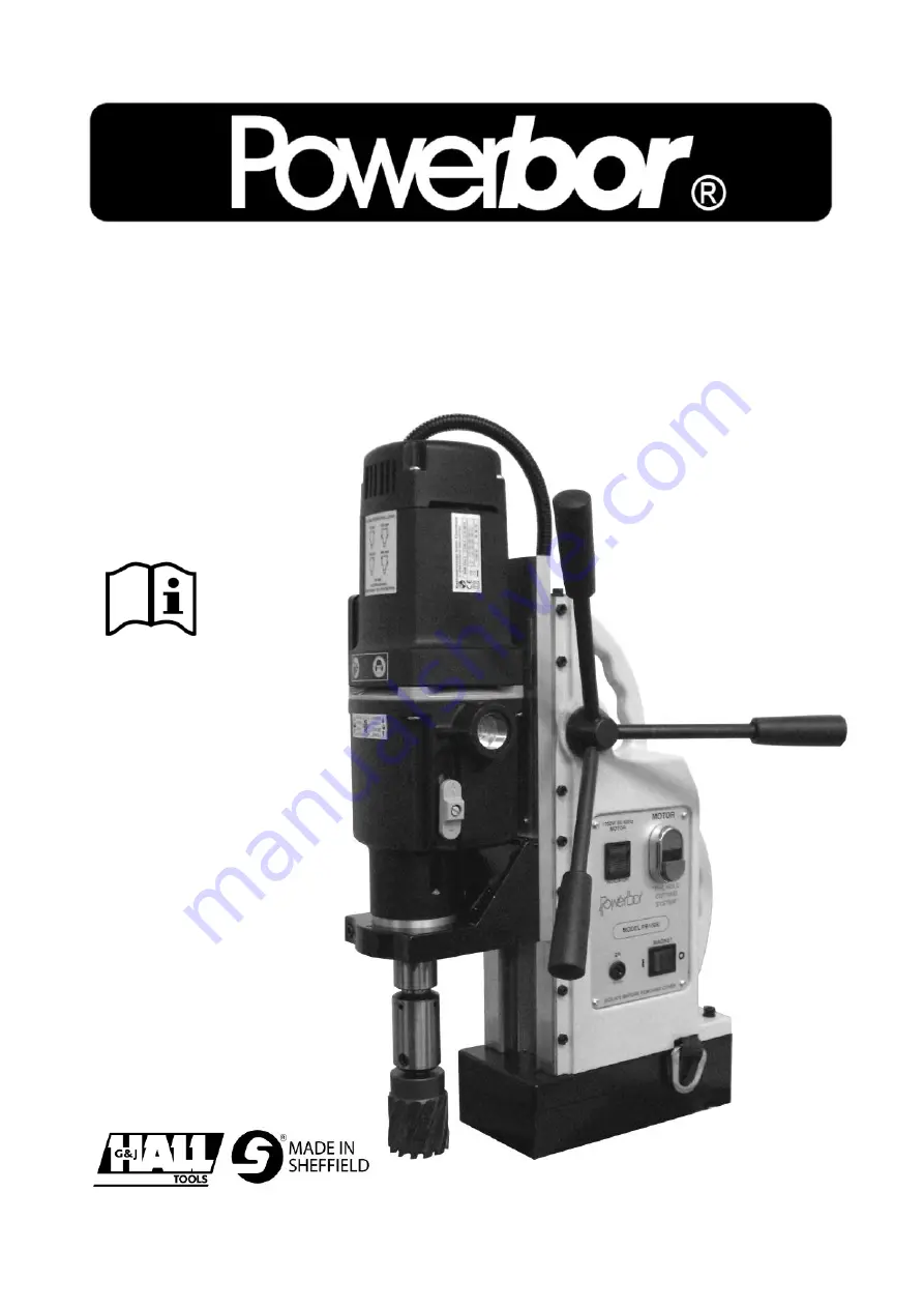
Machine shown
PB1000E - without the
safety guard for clarity.


