background image


Package Contents 


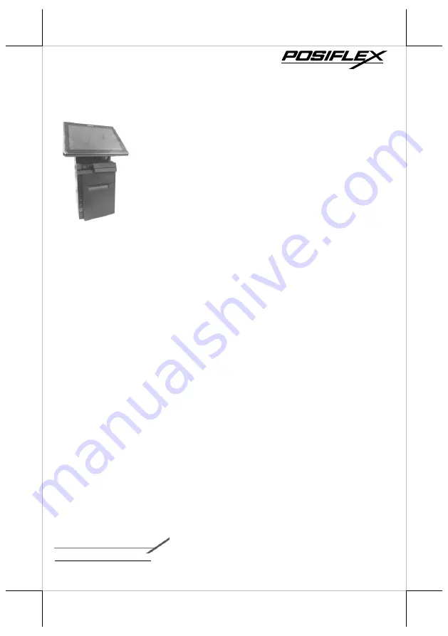
HS-3510W/3512W/3514W desktop POS  (x 1) 


24V/60W Power Adaptor  (x 1) 


Power cord  (x 1) 


3-inch wide thermal paper roll (x 1) 


Paper separator for 2” thermal paper roll (x 1) 


Desktop mounting kit pack for HS-3510/3512  (x 1) 
(including 1 desktop mounting bracket,  
4 fixing screws, and 4 plastic anchors) 


Desktop mounting kit pack for HS-3514  (x 1) 
(including 1 bottom plate, 1 desktop mounting 
bracket, 4 fixing screws, and 4 plastic anchors) 


User manual (x 1) 

Product Feature 


Innovative All-in-one Terminal


This compact all-in-one 10”/12”/14” touch POS now comes with a 
detachable receipt printer for easy maintenance. Add an optional 2D 
barcode scanner while the printer is on board, making HS-
3510W/3512W/3514W the most well-rounded all-in-one POS terminal 
in the market. 


Integrated Design with Advanced Manageability


HS-series integrates the most widely used peripherals including 3” 
thermal printer, MSR, fingerprint sensor, 2D barcode scanner and 2nd 
customer display to support your daily POS operation. The detachable 
modularized design allows quick access to the components, enabling fast 
and easy service and upgrades. 


Aesthetics


Dressed from head to toe in timeless black or white color, the only trend 
that never goes out of style, and with stylish touches added throughout, 
HS-series is not just a piece of machinery, it is an elegantly crafted piece 
of art that looks right at home in any store decoration. 


15650900070 Ver. F0


http://www.posiflex.com


HS-3510W/3512W/3514W 

       JIVA Desktop POS 

         User Manual 

Summary of Contents for HS-3510W

Page 1: ...ile the printer is on board making HS 3510W 3512W 3514W the most well rounded all in one POS terminal in the market Integrated Design with Advanced Manageability HS series integrates the most widely used peripherals including 3 thermal printer MSR fingerprint sensor 2D barcode scanner and 2nd customer display to support your daily POS operation The detachable modularized design allows quick access...

Page 2: ...tor Printer Paper Out LED Indicator 3 Track Magnetic Stripe Reader Optional Printed Paper Exit HS 3510W 3512W 3514W P CAP Touch LCD Panel Fingerprint or iButton Sensors Optional Posiflex 2D Scanner Optional Paper Jam Rescue Compartment Top I O Interface Cable Cover Bottom I O Interface Cable Cover Feed Button ...

Page 3: ...3 Left Side View Right Side View Power Button Paper Roll Cover Release Lever RFID Card Reader Optional ...

Page 4: ...4W Top I O Interface Bottom I O Interface Bottom I O Interface DB 9 COM Ports Rubber Pad DB 25 Parallel Port PS 2 Port USB 2 0 Port RJ 50 COM Port VGA Port USB Ports RJ 10 Cash Drawer Port 24V DC IN Power Jack RJ 45 LAN Port Line Out Rubber Pad Mounting holes ...

Page 5: ...er 3 Connect power adapter and I O cables to the bottom I O interface 4 Have the cover join to the wedge portions of the bottom I O interface 5 Before pushing the cover back into place neatly thread the cables through the cable exit 6 Press down the cover to close the bottom I O interface chamber Adjusting LCD Monitor for a Better Viewing Angle For an optimal viewing angle please tilt the LCD moni...

Page 6: ...r place paper separator in the paper roll compartment by following the instructions below If you are using 3 paper roll for the printer please skip to next step 2 1 Hold the separator with the sharp pointed side down 2 2 Push the sharp pointed part of paper separator into the slot on the bottom of the paper roll compartment 2 3 Slide another side of paper separator into the slot on the top of the ...

Page 7: ...ds towards the paper cutter 5 Make sure the loose end sticks out of the opening of the paper roll compartment Then close the paper roll cover by pushing it back at the center of the top side of the cover with a click sound 6 Make sure the paper roll is well loaded with the end of the paper sticking out as shown in the figure To avoid paper jam or other printing errors do NOT press the paper roll c...

Page 8: ...ep rotating the wheel until the cutter blade is completely retracted 4 Observe the cutter position through the paper exit slot to ensure the cutter blade moves upward to the retracted position 5 Gently push down paper roll cover release lever to open the paper roll cover If the cover is still stuck please repeat Step 3 and Step 4 6 Remove the jammed paper reinstall the paper roll and then close th...

Page 9: ...the paper roll cover 3 Inside the paper roll compartment remove the two screws indicated by the arrows 4 While supporting the terminal with one hand grab the right hand side of the terminal and then pull the front cover towards you with force to separate the printer module from the rear case of HS series 5 From the left hand side of the terminal remove the front cove from the rear case 6 Disconnec...

Page 10: ... B USB port on the control board 7 4 Plug the cable to DC IN power jack on the control board 8 Carefully support the printer module with both of your hands and then push it back into the rear case of HS series terminals 9 After ensuring the front cover is well attached to the rear case insert the two screws back into the screw holes inside the compartment secure them and then close the cover 10 In...

Page 11: ...ate for HS 3514 1 Take the bottom plate with the mounting bracket out of the package and place it with its screw holes on the top in your preferred position 2 Support your POS terminal with its screen facing towards you Then align the two screw bolts on the bottom of the POS with the rail slots of the mounting bracket 3 Push the POS backwards along the rail slots of the bracket until the terminal ...

Page 12: ...two holes on the surface Each hole has to be at least 4 1 or 6 25 mm diameter and 8 3 1 or 35mm in depth 3 Insert two plastic anchors into the holes you drilled in step 2 and use a hammer to tap the plastic anchors into the drilled holes 4 After well attaching two screw holes of the mounting bracket to the plastic anchors insert two self tapping screws into the plastic anchors through the mounting...

Page 13: ...h hole also has to be at least 4 1 or 6 25 mm diameter and 8 3 1 or 35mm in depth 7 2 Push the POS in the direction shown by the arrow to reomve it from the mouting bracket 7 3 After pushing two plastic anchors into the drilled holes tap the plastic anchors into the drilled holes with a hammer 7 4 Refer Step 6 to mount the POS to the bracket 7 5 Apply two self tapping screws through the mounting h...

Page 14: ...e 4G SIM card slot inside printer compartment as indicated in the figure 2 Slide 4G SIM card into the SIM card slot with its gold contacts facing towards you To remove the SIM card push it again to pop it out of the card slot 3 After ensuring the SIM card is well inserted push power button to power on your terminal After HS 3500 series successfully boots to Windows systems wait a moment for the Ne...

Page 15: ... cannot restart or shut down normally due to the unexpected reasons In such a case you should initiate a shutdown by keeping holding down the power button more than 10 seconds Status LED Indicator After HS 3510W 3512W 3514W is powered on it is significant to observe the status of LED indicators anytime to ensure your system functions normally More importantly knowing how to interpret the status in...

Page 16: ...h its hand free design it offers a more convenient solution for users to read 1D 2D barcodes and then transmitted scanned data to the terminal for further processing which greatly increases your working efficiency By default the scanner is set to Auto Trigger operational mode Also to adjust the scanning angle of the scanner you may tilt the scanner up and down as indicated in the figure below Usin...

Page 17: ...essing In this case you may either choose to reboot your printer or keep pressing Feed button to further create the hex dump and Ethernet info print outs until the indicator stops blinking red Software Switch Reset Software Switch Reset is the specially designed function aimed to facilitate the factory reset process Please go through the following instructions to reset your printer to factory sett...

Page 18: ...cond display the step by step instructions are provided in its own user guide to help you mount it onto your POS system Please refer to the relevant user manual for detailed information Installing an Operating System You are highly advised NOT to install an operating system on HS 3510W 3512W 3514W without professional instructions Not only might the careless handling during installation cause irre...

Page 19: ... I O plate Parallel Port 1 CR Port 1 Port controlling 2 CR 24V drive VGA Port D SUB 15 pin with 12V power for Posiflex LCD monitors Standard USB Port 4 x USB 2 0 ports one on the top I O plate and the other three on the bottom I O plate Audio Port Line Out DC In Jack 1 x 24V DC In on bottom I O plate Ethernet Port 1 x 10 100 1000 Mb LED Indicator Power ON standby bi color LED indicators Ethernet l...

Page 20: ...ical approx 26 4 Supported Symbology UPC EAN Code 39 Codabar Interleaved 2 of 5 Matrix 2 of 5 POSTNET MSI Plessey UK Plessey Code 128 GS1 Databar GS1 Databar Limited GS1 Databar Expanded QR Code PDF417 The product information and specifications are subject to change without prior notice To get the detailed information on the HS 3510W 3512W 3514W please check this model from Posiflex Global Website...

Reviews: