

ENGLISH (Translated from Italian)
ENGLISH (Translated from Italian)
ENGLISH (Translated from Italian)
ENGLISH (Translated from Italian)
ENGLISH (Translated from Italian)
ENGLISH (Translated from Italian)
SB325M
MANUALE D’USO, MANUTENZIONE
E CALIBRAZIONE
Bulletin M0220B IT-EN_00
IT
SUZZARABLUE
AUTOMATIC
NOZZLE METER
USE, CALIBRATION
AND MAINTENANCE MANUAL
EN
INDEX
A
DECLARATION OF CONFORMITY
B
GENERAL WARNINGS
C
FIRST AID RULES
D
GENERAL SAFETY RULES
E
TO KNOW SB325 M
E1
INTENDED USE
F PACKAGING
G
TECHNICAL CHARACTERISTICS
H INSTALLATION
I
USE MODALITY
I1
MECHANICAL CHARACTERISTICS
I2
ELECTRONIC CHARACTERISTICS
L
MISFILLING (optional)
M
PRELIMINARY CHECK
N
INITIAL START UP
O1
USER BUTTONS
O2
BATTERY HOUSING
P
DAILY USE
P1
DISPENSING IN NORMAL MODE
P1.1
PARTIAL RESET (NORMAL MODE)
P1.2
RESETTING THE RESET TOTAL
P2
DISPENSING WITH FLOW RATE MODE DISPLAY
P2.1
PARTIAL RESET (FLOW RATE MODE)
Q CALIBRATION
Q1
WHY CALIBRATE?
Q2 DEFINITIONS
Q3
KEY
Q4
CALIBRATION MODE
Q4.1
DISPLAY OF CURRENT CALIBRATION FACTOR AND
RESTORING
FACTORY
FACTOR.
Q4.2
IN FIELD CALIBRATION
Q4.2.1
IN-FIELD CALIBRATION PROCEDURE
Q4.3
DIRECT MODIFICATION OF K FACTOR
R
METER CONFIGURATION
S MAINTENANCE
T MALFUNCTIONS
T1
MECHANICAL MALFUNCTIONS
T2
ELECTRONIC MALFUNCTIONS
U
TECHNICAL DATA
V DISPOSAL
Z DIMENSIONS
A DECLARATION OF CONFORMITY
The undersigned:
PIUSI S.p.AVia Pacinotti 16/A z.i.Rangavino
46029 Suzzara - Mantova - Italy
HEREBY STATES
under its own responsibility, that the equipment described below:
Descriprion: Dispenser nozzle featuring integrated mete
Model: SB325 M
Serial number: refer to Lot Number shown on CE plate affixed to productYear of manufacture: refer to the
year of production shown on the CE plate affixed to the productis in conformity with the legal provisions
indicated in the directives :
- Electromagnetic Compatibility Directive 2004/108/EC
The documentation is at the disposal of the competent authority following motivated request at Piusi
S.p.A. or following request sent to the email address: [email protected] person authorised to compile
the technical file and draw up the declaration is Otto Varini as legal representative.
Suzzara,
01/01/2012
Otto
Varini
legal
representative.
B GENERAL WARNINGS
Important
precautions
To ensure operator safety and to protect the pump from
potential damage, workers must be fully acquainted
with this instruction manual before performing any
operation.
Symbols used
in the manual
The following symbols will be used throughout the
manual to highlight safety information and precautions
of particular importance:
ATTENTION
This symbol indicates safe working practices for operators
and/or potentially exposed persons.
WARNING
This symbol indicates that there is risk of damage to the equip-
ment and/or its components.
NOTE
This symbol indicates useful information.
Manual preser-
vation
This manual should be complete and legible
throughout. It should remain available to end users and
specialist installation and maintenance technicians for
consultation at any time.
Reproduction
rights
All reproduction rights are reserved by Piusi S.p.A. The
text cannot be reprinted without the written permis-
sion of Piusi S.p.A.
© Piusi S.p.A.
THIS MANUAL IS THE PROPERTY OF PIUSI S.p.A.
ANY REPRODUCTION, EVEN PARTIAL, IS FORBIDDEN.
C FIRST AID RULES
Contact with the
product
In the event of problems developing following EYE/SKIN CONTACT,
INHALATION or INGESTION of the treated product, please refer to the
SAFETY DATA SHEET of the fluid handled
.
NOTE
Please refer to the safety data sheet for the product
SMOKING
PROHIBITED
When operating the dispensing system and in particular during refuel-
ling, do not smoke and do not use open flame.
WARNING
Keep the product to be dispensed away from eyes and skin
Keep the product to be dispensed out of reach of children
The nozzle must only be used for the purposes for which it was designed
Using unsuitable component parts and materials could be hazardous
Not checking correct part installation could be hazardous.
D GENERAL SAFETY RULES
Essential protec-
tive equipment
characteristics
Wear protective equipment that is:
• suited to the operations that need to be performed;
• resistant to cleaning products.
ATTENTION
It is a good practice to consider the instructions manual as
an integral part of the purchased product. Always keep the
instructions manual nearby the product.
Personal protec-
tive equipment
that must be worn
Wear the following personal protective equipment during handling
and installation:
safety shoes;
close-fitting clothing;
protective gloves;
safety goggles;;
Protective gloves
Prolonged contact with the treated product may cause skin irritation;
always wear protective gloves during dispensing.
ATTENTION
Do not proceed to dispense if the suction/supply hose, the nozzle or
the safety devices are damaged.
E TO KNOW SB325 M
FOREWORD
Dispenser nozzle featuring integrated meter, made of non-conduc-
tive plastic and designed for use with water/urea solution (AUS32/
DEF). The meter integrated with the SB325 M nozzle uses a turbine
measuring system and interfaces with the user by means of the LCD
display. SB325 M is also compatible with water and food liquids..
E1 INTENDED USE
SB325 M
WATER/UREA SOLUTION - D.E.F. - AUS 32, ACCORDING TO DIN 70070, WATER,
WINDSCREEN
CONDITIONS
OF USE AND
ENVIRONMENTAL
CONDITIONS
Refer to the product technical sheets
F PACKAGING
FOREWORD
THE NOZZLES ARE SUPPLIED PACKED IN CARDBOARD BOXES, WITH LA-
BEL SHOWING FOLLOWING DETAILS:
1 - Package contents
SB325 M
2 - Weight
3 - Product description
G TECHNICAL CHARACTERISTICS
Description
M
in. flo
w
-ra
te (l/min)
M
ax. flo
w
-ra
te
(l/min)
Pr
essur
e loss a
t 35 l/
min (bar)
Inlet thr
ead with
swiv
el
Ex
ternal diamet
er
hose
-end
fitting
(mm)
M
ax. op
er
ating pr
es
-
sur
e (bar)
W
eigh
t (K
g)
SB32 M
15
45
0.9
1” GAS
20
3.5
0,8
H INSTALLATION
FOREWORD
The automatic nozzles are supplied ready for use.
The nozzle features SWIVEL hose-end fitting (complete with O-ring)
useful for connecting to the supply hose.
TO ENSURE PERFECT OPERATION, THE DEVICE MUST BE USED TO
DISPENSE FLUIDS WITH CHARACTERISTICS FALLING WITHIN THE
FOLLOWING PARAMETERS:
- Qmin .: 15 l/min
- Qmax: 45 l/min
- Pmin. : 1,5 bar
- Pmax: 3,5 bar
ATTENTION
During installation, use adequate sealants, being careful no
residues remain inside the hose.
So as not to negatively affect product operation, couple the hose-end
fitting with the hose without using tools such as pliers, etc.
Assembly will be easier if the swivel hose-end fitting is already fitted
on the nozzle.
Make sure the hoses and the suction tank are without threading scale or
residues which could damage the nozzle and the accessories.
WARNING
Apply adequate sealants on the male threads of the connec-
tions and swivels
Do not use Teflon tape
NO TEFLON TAPE
I USE MODALITY
I1 MECHANICAL CHARACTERISTICS
FOREWORD
The main feature of these nozzles is that they are easy to use.
Two operating modes are available:
1
ASSISTED MODE
Dispense by operating the nozzle lever. To interrupt dispensing man-
ually, release the lever.
2
AUTOMATIC MODE
Use the opening lever lock device for automatic dispensing.
To continue dispensing after automatic stop, the lever must be fully
released before proceeding to operate it again.
To interrupt dispensing in manual mode, press the lever again, there-
by releasing the device, and then release.
ATTENTION
DO NOT USE THE NOZZLE OUTSIDE THE PARAMETERS INDI-
CATED ON THE ”TECHNICAL SPECIFICATIONS” CHART
Dispensing is automatically interrupted thanks to the
shut-off device, which operates when the level of the liquid
reaches the end of the spout.
I2 ELECTRONIC CHARACTERISTICS
ATTENTION
The user can choose between two different operating
modes:
1 - Normal Mode
Normal Mode: Mode with display of Partial and Total dispensed quantities
2 - Flow rate Mode
Flow Rate Mode: Mode with display of Flow Rate, as well as Partial
dispensed quantity.
Note
The meter features a non-volatile memory for storing the dispensing
data, even in the event of a complete power break for long periods. The
measurement electronics and the LCD display are fitted in the top part
of the meter which remains isolated from the fluid-bath measurement
chamber and sealed from the outside by means of a cover.
L MISFILLING (optional)
PREMISE
Refuelling with the nozzle equipped with “magnet switch” is
only possible in combination with the “magnet adapter” , so
misfuelling into tanks is made impossible
OPERATION
The “magnet switch” is a fixed magnetic field within the filler necks of
the nozzle. This opens the magnet switch in the spout, so it is only pos-
sible to dispense from the tank where the magnet adaptor is installed.
ATTENTION
Nozzles equipped with “magnet switch” work only in combi-
nation with the “magnet adapter”. The “magnet adapter” is
an optional to be bought separately.
M PRELIMINARY CHECK
WARNING
Check the correct operation of the lock device, according to the fol-
lowing procedure:
1 Take a graduated receptacle with a capacity of 20 litres (5 gal)
LOW
CLIP
2 Begin dispensing into the receptacle, setting the lever in the mini-
mum flow position, until the receptacle is full.
5 cm
3 Keeping the lever open, make sure the spout is submerged by about
5 cm (2 inches).
4 The nozzle must stop, with a click of the lever.
MEDIUM
CLIP
HIGH CLIP
5 Repeat the same operations with the lever in medium-flow and
maximum-flow position.
Check the correct operation of the stop device as described above.
6 If the nozzle stops during dispensing, check and reduce the flow.
7 If the shut-off device does not begin to operate, check the minimum
flow rate of the system or replace the nozzle.
N INITIAL START UP
FOREWORD
Only start dispensing after making sure that assembly and installa-
tion have been correctly performed.
ATTENTION
It is a good practice to only operate the nozzle lever after
making sure the spout has been properly inserted in the
mouth of the tank to be filled.
NOTE
When using for the first time and every time the nozzle is used, fol-
lowing the connection of the supply hose, gently operate the lever
to enable the air to escape from the circuit, until normal operation
is achieved.
ATTENTION
Check the correct operation of the automatic stop device
once the tank is full.
THE FAULTY OPERATION OF THIS DEVICE COULD CAUSE THE
SPILL OF LIQUIDS THAT ARE HAZARDOUS FOR PEOPLE AND
THE ENVIRONMENT.
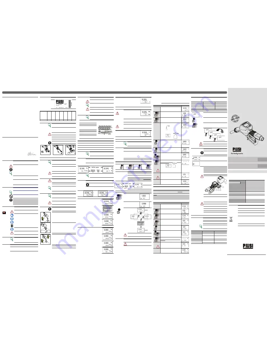
O WHAT IT LOOKS LIKE
FOREWORD
The “LCD” of the METER features two numerical registers and various
indications displayed to the user only when the applicable function
so requires.
1 Partial register (5 figures with moving comma
FROM 0.1 to 99999) indicating the volume dis-
pensed since the reset button was last pressed
4
5
6
9
7
1
2
3
8
2 Indication of battery charge
3 Indication of calibration mode
4 Totals register (6 figures with moving comma FROM
0.1 to 999999), that can indicate two types of Total:
4.1. General Total that cannot be reset (TOTAL)
4.2. Resettable total (Reset TOTAL)
5 Indication of total multiplication factor (x10 / x100 )
6
Indication of type of total, (TOTAL / Reset TOTAL);
7 Indication of unit of measurement of Totals:
L=Litres Gal=Gallons
8
Indication of Flow Rate mode
9 Indication of unit of measurement of Partial:
Qts=Quarts
Pts=Pints
L=Litres
Gal=Gallons
O1 USER BUTTONS
FOREWORD
The METER features two buttons (RESET and CAL) which individually perform two
main functions and, together, other secondary functions.
MAIN FUNCTIONS
PERFORMED
- for the RESET key, resetting the partial register and Reset Total
- for the CAL key, entering instrument calibration mode
SECONDARY
FUNCTIONS
Used together, the two keys permit entering configuration mode where the de-
sired unit of measurement can be set.
LEGEND
CALIBRATE MEANS PERFORMING ACTIONS ON THE METER KEYS. BELOW IS THE
LEGEND OF THE SYMBOLS USED TO DESCRIBE THE ACTIONS TO BE PERFORMED
O2 BATTERY HOUSING
NOTE
K24 is powered by two 1.5V standard type batteries (size AAA). The
battery housing is easily accessible and is closed by a cover with seal.
Everything is easily removable by taking off the rubber protection
around the nozzle and loosening the screws which secure the cover.
P DAILY USE
FOREWORD
The only operations that need to be done for daily use are partial and/or reset-
table total register resetting. The user should use only the dispensing system of
k24. Occasionally the meter may need to be configured or calibrated. To do so,
please refer to the relevant chapters.
Below are the two typical normal operation displays. One display page shows the partial and reset total
registers. The other shows the partial and general total. Switchover from resettable total to general total
display is automatic and tied to phases and times that are in factory set and cannot be changed.
Note
6 digits are available for Totals, plus two icons x 10 / x100. The incre-
ment sequence is the following:
0.0 -> 99999.9 -> 999999 -> 100000 x 10 -> 999999 x 10 ->100000 x
100 -> 999999 x 100
P1 DISPENSING IN NORMAL MODE
FOREWORD
Normal mode is the standard dispensing. While the count is made, the partial and
resettable total are displayed at the same time (reset total).
WARNING
Should one of the keys be accidentally pressed during dispensing,
this will have no effect.
stand by
A few seconds after dispensing has ended, on the lower register, the display
switches from resettable total to general total: the word reset above the word
total disappears, and the reset total is replaced by the general total. This situa-
tion is called standby and remains stable until the user operates the k24 again.
P1.1
PARTIAL RESET (NORMAL MODE)
The partial register can be reset by pressing the reset key when the
meter is in standby, meaning when the display screen shows the
word “TOTAL”.
After pressing the reset key, during reset, the display screen first of
all shows all the lit-up digits and then all the digits that are not lit up.
At the end of the process, a display page is first of all shown with the
reset partial and the reset total
and, after a few moments, the reset total is replaced by the non reset-
tableTotal.
P1.2
RESETTING THE RESET TOTAL
The reset total resetting operation can only be performed after reset-
ting the partial register. The reset total can in fact be reset by pressing
the reset key at length while the display screen shows reset total as
on the following display page:
Schematically, the steps to be taken are:
1 Wait for the display to show normal standby display page (with
total only displayed)
2 Press the reset key quickly
3 The meter starts to reset the partia
4 While the display page showing the reset total is displayed
Press the reset key again for at least 1 second
5
The display screen again shows all the segments of the display
followed by all the switched-off segments and finally shows
the display page where the reset Reset Total is shown.
P2 DISPENSING WITH FLOW RATE MODE DISPLAY
It is possible to dispense fluids, displaying at the same time::
1 the dispensed partial
2 the Flow Rate in [Partial Unit / minute] as shown on the following
display page:
Procedure for entering this mode:
1 wait for the Remote Display to go to Standby, meaning the display screen shows Total only
2 quickly press the CAL key.
3 Start dispensing
The flow rate is updated every 0.7 seconds. Consequently, the display could be relatively unstable at
lower flow rates. The higher the flow rate, the more stable the displayed value.
ATTENTION
The flow rate is measured with reference to
the unit of measurement of the Partial. For
this reason, in case of the unit of measure-
ment of the Partial and Total being dif-
ferent, as in the example shown below, it
should be remembered that the indicated
flow rate relates to the unit of measure-
ment of the partial. In the example shown,
the flow rate is expressed in Qts/min.
The word “Gal” remaining alongside the flow rate refers to the register of the To-
tals (Reset or NON Reset) which are again displayed when exiting from the flow
rate reading mode.
To return to “Normal” mode, press the CAL key again. If one of the two keys RESET
or CAL is accidentally pressed during the count, this will have no effect.
ATTENTION
Even though in this mode they are not displayed, both the Reset Total
and the General Total (Total) increase. Their value can be checked
after dispensing has terminated, returning to “Normal” mode, by
quickly pressing CAL.
P2.1
PARTIAL RESET (FLOW RATE MODE)
To reset the Partial Register, finish dispensing and wait for the Remote
Display to show a Flow Rate of 0.0 as indicated in the illustration
then quickly press RESET
Q CALIBRATION
Q1 WHY CALIBRATE?
Note
When working in extreme operating or flow conditions, (close to
minimum or maximum acceptable range values), it may be a good
idea to calibrate in the field, in the real conditions in which the
SB32 M has to work..
Q2 DEFINITIONS
CALIBRATION FAC-
TOR OR
“K FACTOR”
Multiplication factor applied by the system to the electrical pulses received, to
transform these into measured fluid units.
FACTORY K
FACTOR
Factory-set default factor. It is equal to 1,000. This calibration factor ensures ut-
most precision in the following operating conditions:
Fluid
water/urea solution or liquid food products Temperature:
20°C
Flow rate: 10 - 30 ltr/min
Even after any changes have been made by the user, the factory k factor can be
restored by means of a simple procedure.
USER K FACTOR:
Customized calibration factor, meaning modified by calibration.
Q3 KEY
LEGEND
CALIBRATE MEANS PERFORMING ACTIONS ON THE METER KEYS. BELOW IS THE
LEGEND OF THE SYMBOLS USED TO DESCRIBE THE ACTIONS TO BE PERFORMED
SHORT
PRES-
SURE OF
CAL KEY
CAL
LONG
PRES-
SURE OF
cal KEY
CAL
CAL
CAL
short
pressure
of reset
key
RESET
long
pressure
of reset
key
RESET
RESET
RESET
Q4 CALIBRATION MODE
Why calibrate?
1
Display the currently used calibration factor:
2
Return to factory calibration (Factory K Factor) after a previous cali-
bration by the user
3
Change the calibration factor using one of the two previously indi-
cated procedures
FOREWORD
Two procedures are available for changing the Calibration Factor:
1
In-Field Calibration, performed by means of a dispensing operation
2
Direct Calibration, performed by directly changing the calibration factor
In calibration mode, the partial and total dispensed quantities indicated on the display screen take on
different meanings according to the calibration procedure phase.
In calibration mode, the K24 cannot be used for normal dispensing operations.
In “Calibration” mode, the totals are not increased
ATTENTION
The K24 features a non-volatile memory that keeps the data
concerning calibration and total dispensed quantity stored for
an indefinite time, even in the case of a long power break; after
changing the batteries, calibration need not be repeated.
Q4.1
DISPLAY OF CURRENT CALIBRATION
FACTOR AND RESTORING FACTORY FACTOR.
CAL
CAL
CAL
By pressing the CAL key while the appliance is in
Standby, the display page appears showing the
current calibration factor used. If no calibration
has ever been performed, or the factory setting
has been restored after previous calibrations,
the following display page will appear: The
word “Fact” abbreviation for “factory” shows
that the factory calibration factor is being used
If, on the other hand, calibrations have been
made by the user, the display page will appear
showing the currently used calibration factor ( in
our example 0,998) . The word “user” indicates a
calibration factor set by the user is being used..
CAL
The flow chart alongside shows
the switchover logic from one
display page to another
In this condition, the Reset key
permits switching from User fac-
tor to Factory factor.
To confirm the choice of cali-
bration factor, quickly press
CAL while “User” or “Fact” are
displayed.
After the restart cycle, the K24
uses the calibration factor that
has just been confirmed
CAL
CAL
CAL
CAL
RESET
RESET
TIME OUT
ATTENTION
When the Factory Factor is confirmed, the old User factor is
deleted from the memory
Q4.2
IN FIELD CALIBRATION
FOREWORD
This procedure calls for the fluid to be dispensed into a graduated sample con-
tainer in real operating conditions ( flow rate, viscosity, etc.) requiring maximum
precision.
ATTENTION
For correct K24 calibration, it is most important to:
1
When the Factory Factor is confirmed, the old User factor is deleted from the
memory
2
use a precise Sample Container with a capacity of not less than 5 litres, featuring
an accurate graduated indicator.
3
ensure calibration dispensing is done at a constant flow rate equivalent to that of
normal use, until the container is full;
4
Not reduce the flow rate to reach the graduated area of the container during
the final dispensing stage (the correct method during the final stages of sample
container filling consists in making short top-ups at normal operation flow rate) ;
5
after dispensing, wait a few minutes to make sure any air bubbles are eliminated
from the sample container; only read the Real value at the end of this stage, dur
-
ing which the level in the container could drop.
6
Carefully follow the procedure indicated below.
Q4.2.1
IN-FIELD CALIBRATION PROCEDURE
ACTION
DISPLAY
1
NONE
NEXT in Standby
2
CAL
CAL
CAL
LONG CAL key keying
The NEXT enters calibration mode, shows <<CAL>> and displays
the calibration factor in use instead of partial. The words “Fact” and
“USER” indicate which of the two factors (factory or user) is currently
in use.
Important: This factor is that which the instrument also uses for field
calibration measurement operations
3
RESET
RESET
RESET
LONG RESET key keying
The NEXT shows “CAL” and the partial at zero. The NEXT is ready to
perform in-field calibration.
4
DISPENSING INTO SAMPLE CONTAINER
Without pressing any key, start dispensing into the sample container
Dispensing can be interrupted and started again at will. Continue
dispensing until the level of the fluid in the sample container has
reached the graduated area. There is no need to reach a preset
quantity.
Indicated value Real value
5
RESET
SHORT RESET key keying
The NEXT is informed that the calibration dispensing operation is
finished.
Make sure dispensing is correctly finished before performing this operation.
To calibrate the NEXT, the value indicated by the partial totaliser (example
9.800) must be forced to the real value marked on the graduated sample
container. In the bottom left part of the display an arrow appears (upwards
and downwards), that shows the direction (increase or decrease) of the value
change displayed when the following operations 6 or 7 are performed.
6
RESET
SHORT RESET key keying
The arrow changes direction. The operation can be repeated to
alternate the direction of the arrow.
7
CAL
CAL
CAL
CAL
SHORT/LONG CAL key keying
The indicated value changes in the direction indicated by the arrow
- one unit for every short CAL key keying
- continually if the CAL key is kept pressed. The speed increase rises
by keeping the key pressed. If the desired value is exceeded, repeat
the operations from point (6).
8
RESET
RESET
RESET
LONG RESET key keying
The NEXT is informed that the calibration procedure is finished.
Before performing this operation, make sure the INDICATED value is
the same as the REAL value.
.
Indicated value Real value
The NEXT calculates the new USER K FACTOR ; this calculation could
require a few seconds, depending on the correction to be made
ATTENTION: If this operation is performed after action (5), without
changing the indicated value, the USER K FACTOR would be the
same as the FACTORY K FACTOR, thus it is ignored.
9
NO OPERATION
At the end of the calculation, the new USER K FACTOR is shown for
a few seconds, after which the restart cycle is repeated to finally
achieve standby condition.
IMPORTANT: From now on, the indicated factor will become the
calibration factor used by the NEXT and will continue to remain
such even after a battery change
10
NO OPERATION
The NEXT stores the new work calibration factor and is ready to
begin dispensing, using the USER K FACTOR that has just been
calculated..
Q4.3
DIRECT MODIFICATION OF K FACTOR
If normal NEXT operation shows a mean percentage error, this can be corrected by applying to the cur-
rently used calibration factor a correction of the same percentage. In this case, the percentage correction
of the USER K FACTOR must be calculated by the operator in the following way
New cal. Factor = Old Cal Factor *
( )
100 - E%
100
Example:
Error percentage found: E% - 0.9 %
CURRENT calibration factor: 1.000
New USER K FACTOR: 1.000 * [(100 – ( - 0.9))/100] = 1.000 * [(100 + 0.9)/100] = 1.009
If the NEXT indicates less than the real dispensed value (negative error) the new calibration factor
must be higher than the old one as shown in the example. The opposite applies if the NEXT shows
more than the real dispensed value (positive error).
ACTION
DISPLAY
1
NONE
METER in Standby.
2
CAL
CAL
CAL
LONG CAL KEY KEYING
NEXT enters calibration mode, shows “CAL” and displays the
calibration factor being used instead of the partial. The words “Fact”
and “User” indicate which of the two factors (factory or user) is
currently being used.
3
RESET
RESET
RESET
LONG RESET KEY KEYING
The NEXT shows “CAL” and the zero partial total.
NEXT is ready to perform in-field calibration by dispensing – see
previous paragraph.
4
RESET
RESET
RESET
LONG RESET KEY KEYING
We now go on to Direct change of the calibration factor: the word
“Direct” appears together with the Currently Used calibration factor.
In the bottom left part of the display, an arrow appears (upwards
or downwards) defining the direction (increase or decrease) of
change of the displayed value when subsequent operations 5 or 6
are performed.
5
RESET
SHORT RESET KEY KEYING
Changes the direction of the arrow. The operation can be repeated
to alternate the direction of the arrow.
6
CAL
CAL
CAL
CAL
SHORT/LONG CAL KEY KEYING
The indicated value changes in the direction indicated by the arrow
- one unit for every short CAL key keying
- continually if the CAL key is kept pressed. The speed increase rises
by keeping the key pressed. If the desired value is exceeded, repeat
the operations from point (5).
7
RESET
RESET
RESET
LONG RESET KEY KEYING
The NEXT is informed that the calibration procedure is finished.
Before performing this operation, make sure the INDICATED value
is that required.
8
NO OPERATION
At the end of the calculation, the new USER K FACTOR is shown for
a few seconds, after which the restart cycle is repeated to finally
achieve standby condition.
IMPORTANT: From now on, the indicated factor will become the
calibration factor used by the NEXT and will continue to remain
such even after a battery change
9
NO OPERATION
The NEXT stores the new work calibration factor and is ready to
begin dispensing, using the USER K FACTOR that has just been
changed.
R METER CONFIGURATION
The METER feature a menu with which the user can select the main measurement unit, Quarts (Qts), Pints
(Pts), Litres (Lit), Gallons (Gal); The combination of the unit of measurement of the Partial register and that
of the Totals is predefined according to the following table:
Combination no.
Unit of Measurement
Partial Register
Unit of Measurement
Totals Register
1
Litres (L)
Litres (L)
2
Gallons (Gal)
Gallons (Gal)
3
Quarts (Qts)
Gallons (Gal)
4
Pints (Pts)
Gallons (Gal)
To choose between the 4 available combinations:
1
Wait for the METER to go to Standby
2
then press the CAL and RESET keys together. Keep these pressed un-
til the word “UNIT” appears on the screen together with the unit of
measurement set at that time (in this example Litres / Litres )
3
RESET
Every short press of the RESET key, the various combinations of the
units of measurements are scrolled as shown below:
4
CAL
CAL
CAL
By pressing the CAL key at length, the new settings will be stored,
the METER will pass through the start cycle and will then be ready to
dispense in the set units.
Gal
Qts
Pts
Gal
RESET
RESET
RESET
ATTENTION
The Reset Total and Total registers will be automatically
changed to the new unit of measurement.
NO new calibration is required after changing the Unit of
Measurement.
S MAINTENANCE
BATTERY
REPLACEMENT
Use 2x1.5 V alkaline batteries size AAA
WARNING
K24 should be installed in a position allowing the batteries to be
replaced without removing it from the system.
K24 features two low-battery alarm levels:
1
When the battery charge falls below the first level on the LCD, the fixed battery
symbol appears.
In this condition, K24 continues to operate cor-
rectly, but the fixed icon warns the user that it is ADVISABLE to change the
batteries.
2
If K24 operation continues without changing the batteries, the second battery
alarm level will be reached which will prevent operation. In this condition the
battery icon starts to flash and is the only one to remain visible on the LCD.
o change the batter-
ies, with reference
to the exploded
diagram positions,
proceed as follows
UNSCREW THE NUT
REMOVE THE COVER (1)
LOOSEN THE SCREW (2)
REMOVE THE COVER (3) RIGHT SIDE
CHANGE THE BATTERIES
ASSEMBLE EVERYTHING BACK ON THE SEAL AROUND THE COVER
HOUSING AND TAKE CARE TO PLACE
ATTENTION
DO NOT OVER-TIGHTEN THE SCREW
1
4
3
2
The K24 will display the same Reset Total, the same Total and the same Partial indicated before the batter-
ies were changed. After changing the batteries, the meter does not need calibrating again.
CLEANING
Only one operation is necessary to clean the k24.
After removing k24 from the plant where it was built in, any residual
elements can be removed by washing or mechanically-handling.
If this operation does not restore a smooth rotation of the turbine, it
will have to be replaced.
ATTENTION
Do not discard the old batteries in the environment. Refer
to local disposal regulations.
Do not use compressed air onto the turbine in order to
avoid its damage because of an excessive rotation
PERIODICALLY CHECK THE CORRECT OPERATION OF THE
AUTOMATIC STOP DEVICE
IF FITTED, IT IS BEST TO PERIODICALLY CHECK THE FILTER AND
CLEAN IT EVERY 1000 LITRES OF TRANSFER.
PERIODICALLY CHECK THE TIGHTNESS OF THE CONNECTIONS
T MALFUNCTIONS
T1 MECHANICAL MALFUNCTIONS
FOREWORD
THE POSSIBLE CAUSES OF MALFUNCTION ARE MAINLY ATTRIBUT-
ABLE TO THREE FACTORS:
1
NOZZLE DIRTY IN INNER HOLE OF LIP AT END OF SPOUT
2
OPERATING PRESSURE OF LIQUID TO BE DISPENSED BELOW 0.5 bar
OR ABOVE 3.5 bar
3
FLOW RATE TOO LOW OR TOO HIGH
NOTE
CORRECT AND REGULAR MAINTENANCE OF THE NOZZLE AND OF
THE SYSTEM TO WHICH IT IS CONNECTED PREVENTS MALFUNC-
TIONS AND POSSIBLE ACCIDENTAL SPILLS OF HAZARDOUS LIQUIDS.
T2 ELECTRONIC MALFUNCTIONS
Problem
Possible cause
Remedial Action
LCD: no indication
Bad battery contact
Check battery contacts
Not enough measurement
precision
Wrong K FACTOR
With reference to paragraph H,
check the K FACTOR
The meter works below
minimum acceptable flow rate.
Increase the flow rate until an ac-
ceptable flow rate range has been
achieved
Reduced or zero flow rate
TURBINE blocked
Clean the TURBINE
The meter does not count,
but the flow rate is correct
Incorrect installation of
gears after cleaning
Repeat the reassembly procedure
Possible electronic card problems Contact your dealer
U TECHNICAL DATA
Measurement system
TURBINE
Resolution (nominal)
Hi Flow
0.010 lit/pulse
Low Flow
0.005 lit/pulse
Flow Rate (Range)
5 ÷ 30 (Litres/minute) FOR AUS32
Operating pressure (Max)
3.5 (Bar)
Storage temperature (Range)
-20 ÷ + 70 (°C)
Storage humidity (Max)
95 (% RU)
Operating temperature (Range)
-10 ÷ + 50 (°C)
Flow resistance
0.90 Bar at 100 lit/min.
Viscosity (Range)
2 ÷ 5.35 cSt
Accuracy
±1% after calibration within
10÷90 (litres/min) 2,65÷23,8 (gallons/min) range
Reproducibility (Typical)
±0,3 (%)
Screen
Liquid crystals LCD. Featuring:
- 5-figure partial
- 6-figure Reset Total plus x10 / x100
6-figure non reset Total plus x10 / x100
Power Supply
2x1.5 V alkaline batteries size AAA
Battery life
18 ÷ 36 months
Protection
IP65
V DISPOSAL
Foreword
If the system needs to be disposed, the parts which make it up must be de-
livered to companies that specialize in the recycling and disposal of industrial
waste and, in particular:
Disposing of packing
materials
The packaging consists of biodegradable cardboard which can be deliv-
ered to companies for normal recycling of cellulose.
Metal Parts Disposal Metal parts, whether paint-finished or in stainless steel, can be consigned to
scrap metal collectors.
Disposal of electric
and electronic com-
ponents
These must be disposed of by companies that specialize in the disposal
of electronic components, in accordance with the indications of directive
2002/96/CE (see text of directive below).
Information
regarding
the
environment
for clients
residing
within the European
Union
European Directive 2002/96/EC requires that all equipment marked with this
symbol on the product and/or packaging not be disposed of together with
non-differentiated urban waste. The symbol indicates that this product must
not be disposed of together with normal household waste. It is the respon-
sibility of the owner to dispose of these products as well as other electric or
electronic equipment by means of the specific refuse collection structures
indicated by the government or the local governing authorities.
Miscellaneous parts
disposal
Other components, such as pipes, rubber gaskets, plastic parts and wires, must
be disposed of by companies specialising in the disposal of industrial waste.
Bulletin M0220B IT-EN_00
PIUSI S.p.A.
Suzzara (MN) Italy


