background image

Summary of Contents for PA-39 Twin Comanche C/R

Page 1: ...PIPER AIRPLANE SERVICE MANUAL CARD 1OF4 0 TWINCOMANCHE PA 30 PA 39 PIPER AIRCRAFT CORPORATION PART NUMBER 753645 REVISED OCT 1 1998 lAl...

Page 2: ...0 Published by TechnicalPublications The New Piper Aircraft Inc 2926PiperDrive VeroBeach Florida 32960 U S A GAMA Member GeneralAviation Manufacturers Association 0 1A2...

Page 3: ...ed in this Aerofiche Service Manual will be kept current by revisionsdistributedperiodically These revisions will supersedeall previous revisions and will be complete Aerofiche card replacementsand sh...

Page 4: ...thru 39 155 PARTS This manualgenerallydoes not containhardwarecalloutsfor installation Hardwarecalloutsare only indicatedwherea specialapplicationis required Toconfirmthe correcthardwareused referto...

Page 5: ...BRAKE SYSTEM POWER PLANT NORMALLY ASPIRATED POWER PLANT TURBOCHARGED FUEL SYSTEM 2A9 2D18 2G1 2121 X INSTRUMENTS 2K14 AEROFICHE CARD NO 3 XI ELECTRICAL SYSTEM 3A9 XII ELECTRONICS 3G12 AEROFICHECARDNO...

Page 6: ...ndingGearStruts C7 2 15 ServicePoints SerialNos 30 1to30 852incl and30 854to 30 901incl 1C11 2 16 ServicePoints SerialNos 30 853 30 902to 30 2000inc IC12 2 17 OilSuctionScreen C19 2 18 OilPressureScre...

Page 7: ...5 14 Trim ScrewAssembly 1110 5 15 Flap Control Installation 1120 5 16 Flap Position Sender Unit 1123 5 17 FabricatedAileron Bellcrank Rigging Tool 1J13 5 18 FabricatedAileron Rigging Tool 1114 5 19 F...

Page 8: ...linderInstallation 2D5 7 27 FabricatedPlumb BobTool 2D9 7 28 FabricatedNoseWheel AlignmentJig 2 10 7 29 FabricatedSpannerWrench 2D11 7 30 Inspectionof RodEndBearings 2D12 7 31 Main GearWear Limits 2D1...

Page 9: ...tion Impulse Coupling Magneto Timing Marks Engine Tuning Marks RemovingSpring From Lead Assembly Assembly Tool Using Assembly Tool Measuring Lead Assembly Length CuttingMetallic Braid From End of Lead...

Page 10: ...edResistanceMethod 3B8 11 8 CheckingVoltageSettingVariableResistanceMethod 3B8 11 9 AdjustingVoltageRegulatorSetting 3B9 11 10 CutoutRelayAir GapCheckandAdjustment 3B I 11 11 CutoutRelayPointOperating...

Page 11: ...mponents SerialNos 30 1to 30 852incl and30 854to30 901 3D20 11 49 ElectricalSystemComponents SerialNos 30 853 30 902to 30 2000 PA 39S N39 1 3D21 NOTE Indexfor ElectricalSchematics maybefoundinTableXI...

Page 12: ...D11 13 26 ExplodedView Combustion AirBlowerandMotorAssembly No 753905 4D15 13 27 SuggestedSet upfor HeaterOperationTest 4D17 13 28 WiringConnectionsfor HeaterOperationTest 4D18 13 29 HeaterFuelValve 4...

Page 13: ...n 5 3 Checking Stabilator Friction 1 Magneto Timing Marks 5 2 Engine TimingMarks 8A 1 Magneto Timing Marks 8A 2 Engine Timing Marks 10 1 Instrument Panel 11 1 Dome Lights Schematic 11 2 Instrument Lig...

Page 14: ...ng Chart Landing Gear System 2D6 vn m Main Gear Wear Limits 2D15 VI IV Nose Gear Wear Limits 2D17 VI I Propeller Specifications PA 30 2E7 VIII IIl Troubleshooting Chart Engine 2F16 VIIIA I PropellerSp...

Page 15: ...g 1 6 Empennage 1 7 Flight Controls 1 8 Landing Gear 1 9 Brake System 1 10 Engines and Propellers 1 11 Fuel System 1 12 Instruments 1 13 Electronic Equipment 1 14 Heating and Ventilating System Aerofi...

Page 16: ...The description of the airplaneincludedin this section is limited to generalinformation Section I givesleading particulars and principal dimensions while each major system is described in its appropr...

Page 17: ...s powered by two Avco Lycoming four cylinder direct drive wet sump horizontally opposed fuel injected engines The propellers are Hartzell full feathering constant speed units controlled by a governor...

Page 18: ...ine instruments and advance flight instruments The panel is shock mounted to minimize vibration to the instruments 1 13 ELECTRONIC EQUIPMENT Provision for electronic equipment includes variois combina...

Page 19: ...LockingAirplane C2 2 18 Towing C2 2 19 Taxiing 1C3 2 20 ExternalPowerReceptacle C4 2 21 Operationof ExternalPowerReceptacle 1C4 2 22 Cleaning 1C4 2 23 CleaningEngineCompartment C4 2 24 CleaningLandin...

Page 20: ...ystem 1C14 2 58 FillingFuelCells 1C14 2 59 DrainingFuelValvesandLines 1C14 2 60 DrainingFuelSystem IC15 2 61 ElectricalSystem 1C15 2 62 ServicingElectricalSystem C15 2 63 OxygenSystem IC15 2 64 Servic...

Page 21: ...PIPER TWIN COMANCHESERVICEMANUAL THISPAGEINTENTIONALLY BLANK Revised 10 1 98 HANDLING AND SERVICING 1A21...

Page 22: ...wing station or buttock line BL and water line WL designations is frequently employed in this manual Refer to Figures 2 3 and 2 4 Fuselage stations buttock lines and water lines are reference points m...

Page 23: ...1 93r PIPER TWIN COMANCHE SERVICE MANUAL 1782 35 11 75 Figure 2 1 Three View of Twin Comanche PA 30 Serial Nos 30 1 to 30 852 inclusive and 30 854 to 30 901 inclusive HANDLING AND SERVICING Issued 12...

Page 24: ...PIPER TWIN COMANCHESERVICE MANUAL 1934 Figure 2 2 Three View of Twin Comanche PA 30 Serial Nos 30 853 30 902 to 30 2000 inclusive HANDLINGAND SERVICING Issued 12 29 72 1A24...

Page 25: ...nd Generator or Alternator Dimensions Height Width Length Oil SAE Number Oil Sump Capacity Oil Consumption Maximum Fuel Aviation Grade Minimum Octane Fuel Injector Bendix Magneto 2 Scintilla Magneto D...

Page 26: ...iationGrade MinimumOctane FuelInjector Bendix Magneto 2 Scintilla MagnetoDrive RatiotoCrankshaft MagnetoDrive Rotation MagnetoTiming MagnetoPointClearance PIPER TWIN COMANCHE SERVICE MANUAL TABLE II I...

Page 27: ...r Voltage Control Prestolite Vacuum Pump Drive Ratio to Crankshaft Vacuum Pump Drive Rotation Propeller Governor Drive Propeller Governor Ratio Fuel Pump SR 88D REM 40E 0 018 to 0 022 in 1 3 2 4 0 5 1...

Page 28: ...lite Over Voltage Control Prestolite Vacuum Pump Drive Ratio to Crankshaft Vacuum Pump Drive Rotation Propeller Governor Drive Propeller Governor Ratio Fuel Pump 171 REB 37N 0 015 to 0 021 in 1 3 2 4...

Page 29: ...hock Strut Type Fluid Required Struts Brakes Strut Extension Static Load Maximum Air Pressure Strut Tread Width from each tire center Wheel Base Nose Wheel Travel Main Wheel Toe In Turning Radius Min...

Page 30: ...Shock Strut Type Fluid Required Struts Brakes Strut Extension Static Load Maximum Air Pressure Strut Tread Width from each tire center Wheel Base Nose WheelTravel Main WheelToe In Turning Radius Min...

Page 31: ...n 8 ft 2 875 in 4 ft 6 in 11 5 in FUSELAGE Length IncludingTailCone Fairing Width WithoutStabilator Height WithoutVertical Fin 23 ft 0 950 in 47 875 in 53 875 in WINGS Span Width Chord Station 25 inch...

Page 32: ...AREAS Total WingArea Including Aileron and Flaps Aileron Flap Stabilator including trim tab Fin Rudder 178 sq ft 14 1 sq ft 20 2 sq ft 32 5 sq ft 9 0 sq ft 5 9 sq ft CONTROL SURFACES TRAVEL I REFER TO...

Page 33: ...PIPER TWIN COMANCHE SERVICE MANUAL Figure 2 3 Station Reference Lines Fuselage HANDLING AND SERVICING Issued 12 29 72 1B9...

Page 34: ...A183 PIPER TWIN COMANCHE SERVICE MANUAL Figure 2 4 Station Reference Lines Wing and Stabilator HANDLING AND SERVICING Issued 12 29 72 1B10...

Page 35: ...R PUSH PULL CONTROLCABLES BRAKE LINE RIGHT GEAR AND TIP TANK FUEL UNE 10 CONTROLCABLE PULLEYCLUSTER BRAKE LINES AUTOPILOT PTTCHSERVO 11 CONTROL CABLES 12 BRAKE LINES MAIN FUEL CELLOUTLET LINE CONTROL...

Page 36: ...PER TWIN COMANCHE SERVICE MANUAL 2 3 4 4 6 S VERTICALFIN ATTACHMENT BOLTS ELT TRANSMITTER 9 RUDDER CONTROLHORN STABILATOR TORQUETUBE STABILATOR CONTROLSTOPS STABILATORTRIM MECHANISM 10 ROTATING BEACON...

Page 37: ...LUID RESERVOIR CENTRAL AIR FILTERHEATER NOSE GEAR PARALLELINGRELAY 7 BAGGAGE AREA 8 OXYGENFILLER 9 VERTICALFIN ATTACHMENT BOLTS ELT TRANSMITTER 10 RUDDERCONTROLHORN STABILATOR TORQUETUBE STABILATOR CO...

Page 38: ...9 WING TIP 10 ENGINECONTROL CABLES ELECTRICALWIRE CONNECTORS FUEL LINE CONNECTIONS STATICAIR LINE CONNECTIONS BRAKE LINE CONNECTIONSAND FRONTAND REARSPAR ATTACHMENT POINTS 11 ENGINE OIL DRAIN 12 FUELC...

Page 39: ...rews Remove the carpet thus exposing the floor panel attaching screws To enter the aft section of the fuselage remove the lower rear baggage compartment upholstery panel by removing the attaching scre...

Page 40: ...hen flared fittings are being installed ascertain that the male threads are properly lubricated Torque the fittings in accordance with Table II IA TABLE II IA FLARE FITTING TORQUES TORQUE INCH POUND I...

Page 41: ...Following isthe formula to be used Refer to Figure 2 8a T Torque desired at the part A Basic lever length from center of wrench shank to center of handle or stamped on wrench or listed for that model...

Page 42: ...ng SSP1776 for torques on parts used on Lycoming engines 8 A maximum of two AN960 washers may beadded under the bolt heads or nuts to correct for variations in material thickness within the tolerances...

Page 43: ...20D AN 364D NAS 1022D FINE THREAD SERIES Nut bolt Torque Limits size in lbs Torque Limits in lbs Torque Limits Torque Limits in lbs in lbs Torque Limits Torque Limits in lbs in lbs Min Max Min Max Min...

Page 44: ...PIPER TWIN COMANCHESERVICE MANUAL TABLE II III DECIMAL CONVERSIONCHART HANDLING AND SERVICING Issued 12 29 72 1B20...

Page 45: ...ys of four parts Devoe non skid compound and one part black enamel are painted on the right wing and flap The lines of rivets on the walkway are covered with non skid paper strips se cured with sculp...

Page 46: ...prevented 2 12 JACKING The airplane is provided with a jack pad on each main spar just outboard of the engine nacelle and a support position by making use of the tail skid Refer to Figure 2 9 To jack...

Page 47: ...weighing procedure while the wheels are on scales or while the wheels are on the ground To level the airplane for purposes of weighing or rigging the following procedures may be used a To longitudina...

Page 48: ...ICE MANUAL t J i A179 Figure 2 11 Leveling Airplane Serial Nos 30 1 to 30 852 incl 30 854 to 30 901 inci AiSO Figure 2 12 Leveling Airplane Serial Nos 30 853 30 902 to 30 2000 inclusive HANDLING AND S...

Page 49: ...ck until the bubble of the levelis centered 2 15 MOORING The airplane should be moored to insure its immovability protection and secunty under various weather conditions The following procedure gives...

Page 50: ...weather when accumulated moisture may freeze the brake 2 17 LOCKINGAIRPLANE The cabin and baggage doors are provided with a key lock The same key can be used to operate both door locks 2 18 TOWING Th...

Page 51: ...a Taxi forward a few feet and apply brakes to determine their effectiveness b Taxi with propeller set in low pitch high RPM setting c While taxiing make slight turns to ascertain the effectiveness of...

Page 52: ...place a strip of tape on the magneto vents to prevent any solvent from entering these units a Place a large pan under the engine to catch waste b With the engine cowling removed spray or brush the eng...

Page 53: ...ashthe airplane thefollowingprocedure maybe used NOTE When hosing down aircraft avoid directing water in the fuel tank vents drain tubes or around the sealedcoverplates and filler cap access openings...

Page 54: ...be cleaned by using an approved air type cleaner or foam upholstery cleaner Carefully follow the manufacturer s instructions Avoid soaking or harsh rubbing CAUTION Solvent cleaners require adequate v...

Page 55: ...s with short strokes approximately one inch and the airplane settles to its normal position within one or two cycles after the rocking force is removed the oleo strut requires inflating Check the valv...

Page 56: ...Place a pan under the gear to catch spillage c At the filler plug relieve air pressure from the strut housing chamber by removing the cap from the air valve and depressing the valve core d There are...

Page 57: ...th fluid if needed 6 Reinstall fill plug and tighten e With the airplane raised retract and extend the gear strut several times to ascertain that the strut actuates freely The weight of the gear fork...

Page 58: ...e filled to the level marked on reservoir with the fluid specified in Table II I The reservoir located on the left side of the forward cabin bulkhead in the nose section refer to Figure 2 15 or 2 16 s...

Page 59: ...7 FILLER AUXILIARY FUEL CELL 8 TIRE MAIN GEAR LAND R 9 ENGINE OIL SUCTIONSCREEN 10 FUEL INJECTOR 1 1 AIR VALVE PROPELLER 12 FILTER ENGINEOIL 13 FILLER ENGINEOIL 14 FILTER ENGINE AIR INTAKE 15 TIRE NOS...

Page 60: ...LCELL 7 TIRE MAINGEAR L ANDR 8 ENGINE OILSUCTION SCREEN 9 FUELINJECTOR 10 AIRVALVE PROPELLER 11 FILTER ENGINE OIL 12 FILLER ENGINE OIL 13 FILTER ENGINE AIRINTAKE 14 BATTERY 15 TIRE NOSEGEAR 16 FILLER...

Page 61: ...LOF AIR FILTER a Remove the right side access panel from the engine nacelle to gain access to the air filter box b Turn the three studs and remove the air filter boxcover c Lift the air filterfrom the...

Page 62: ...line Fill the fuelcellsto thebottomof the fillerneckwiththefuel specifiedon the placardlocatedon theundersideof the fillercover or in TableII I Each main inboard fuelcellholdsa maximumof 30 U S gallon...

Page 63: ...r All electrical wires should be inspected for chafing and bare wires For detailed information on this system refer to Section XI of this manual 2 63 OXYGEN SYSTEM 2 64 SERVICING THE OXYGEN SYSTEM Oxy...

Page 64: ...ystem it is recommended that the following procedurebeused 1 Beforeopeninganyvalves checkthe pressureremaininginthe airplane soxygencylinder If it is stillpartlycharged notethe pressureindicatedon the...

Page 65: ...ery 5 years The lightweight cylinders ICC or DOT 3HT 1850 classification must be hydrostatic tested every 3 years and must be retired from service after 24 years or 4380 pressurizations whichever occu...

Page 66: ...oil drain access plate from bottom of the engine cowl b Remove oil drain plug from bottom of the engine sump It is recommended the engine be warmed to operating temperature to insure complete draining...

Page 67: ...Refer to Figure 2 17 When certain that the screen is properly seated tighten the plug If the plug seems tight this will indicatethat the screen is not properly seated and must be disassembled and the...

Page 68: ...pacting abrasion or pressure Evidenceof internal enginedamage foundin theoil filterjustifiesfurtherexaminationtodeterminethecause c Afterthe elementhas beenreplaced tightenthe attachingbolt within20 t...

Page 69: ...oil may result in high oil consumption as the additives in some of these oils can retard the break in of the piston rings and cylinder walls 2 All new or newly overhauled turbocharged engines must be...

Page 70: ...engine oil may be used as a satisfactory substitute b Check the components to be lubricated for evidence of excessive wear and replace them as necessary c Remove all excess lubricants from components...

Page 71: ...notpackthegreaseintothe wheelhub c Use extracarewhen greasingthe Hartzellpropellerhub to avoidblowingtheclampgaskets Remove onegreasefittingwhileapplyinggreasetotheotherfitting 2 80 LUBRICATION CHART...

Page 72: ...PIPER TWIN COMANCHE SERVICE MANUAL THISPAGEINTENTIONALLY BLANK 0 HANDLING AND SERVICING Revised 10 1 98 1C24...

Page 73: ...ize Compound MIL T 5544 Anti Seize Graphite Petrolatum Fuel Landing Gear Air Valve 6PB Parker Oil MIL G 6032 Lubricating Grease Gasoline and Oil Resistant Pitot and Static TT A 580 JAN A 669 Anti Seiz...

Page 74: ...NG ROUTINE MAINTENANCE CHECKS APPLY LUBRICANT TO MISCELLANEOUS LINKAGES 4 TRANSMISSIONS SHOULD BE DISASSEMBLED CLEANED INSPECTED AND LUBRICATED AT EACH 500 HOUR INTERVAL OR ANNUALLY ACTUATORSCREWS SHO...

Page 75: ...SM NOSEGEARPUSH PULL RODENDBEARING 27 STRUTHOUSING ATTACHMENTBUSHINGS DRAGLINK PIVOTAND ATTACHMENTBUSHINGS 28 SHIMMYDAMPENER RODENDBEARINGANDMOUNT 29 UPPER AND LOWER TORQUELINK BUSHINGS 30 UPPER AND L...

Page 76: ...1913 1 1901 SKETCH A EIPER TWIN COMANCHESERVICE MANUAL Figure 2 20 Lubrication Chart 0 HANDLING ANDSERVICING Revised 1 31 74 1D4...

Page 77: ...0 500 PIPER TWIN COMANCHE SERVICE MANUAL SKETCH I SKETCH 6 AS REQUIRED METHOD HAND or PACK 4 OIL CAN i f a GREASE SPRAYBU HYDRAULIC GU CA BRUSH FLUID Figure 2 20 Lubrication Chart cont Revised 1 31 74...

Page 78: ...N HOUSING DURAHASPARTNO 1010250STAMPED ON TRANSMISSIONHOUSING DISASSEMBLEAND CLEAN WITHA QUICK DRYINGTYPE SOLVENT WHENREASSEMBLING TRANSMISSIONS FILLDUKESTRANSMISSION WITH DUKESNO 4 LUBRICANT OR DURAT...

Page 79: ...N COMANCHE SERVICE MANUAL TABLE II V DECIMAL MILLIMETER EQUIVALENTS OF DRILL SIZES Decimal Millimeter Equivalentsof DrillSizes From1 2 to No 80 Size Decimal Millimeter Added 10 28 82 HANDLING AND SERV...

Page 80: ...limeters Refer to Table II VI A Example Convert 1 5 inches to millimeters 1 Read down inches column to 1 inches 2 Read across top inch column to 0 5 3 Read down and across to find millimeters 1 5 inch...

Page 81: ...100 110 120 130 140 150 160 170 180 190 200 210 F 94 0 76 0 58 0 40 0 22 0 4 0 14 0 32 0 50 0 68 0 86 0 104 0 122 0 140 0 158 0 176 0 194 0 212 0 230 0 248 0 266 0 284 0 302 0 320 0 338 0 356 0 374 0...

Page 82: ...84 2 438 0177 0431 0 685 0 939 1 193 1 447 1 701 1 955 2 209 2 463 0 203 0 457 0 711 0 965 1219 1473 1 727 1981 2 235 2489 0 228 0 482 0 736 0 990 1 244 1498 1 752 2006 2 260 2 514 INCHES 0 00 0 0 01...

Page 83: ...4 1 201 4 546 2688 0 1556 1 164 4 405 231 0 0 1337 3 785 0 8327 128 2540 08333 0 000948 0 7376 METERS MILS MM YARDS M KG BTU KW HR DRAM CU CM CU IN U S GAL LITERS CU IN CU FT U S GAL LITERS LB AVDP SQ...

Page 84: ...SIDES OF HOSE B NONSELF SEALING AROMATIC ANDHEAT RESISTANT HOSE WHITE7 D RED NUMERALS LETTERSAND STRIPE E SELF SEALINGAROMATIC RESISTANTHOSE VRED NUMERALS ANDLETTERS C FLAME AROMATIC ANDOIL RESISTANTH...

Page 85: ...PIPER TWIN COMANCHE SERVICE MANUAL 3 Figure 2 22 Removal of Cherrylock Rivets Added 10 28 82 1D13 1D13 HANDLING AND SERVICING...

Page 86: ...CE BETWEEN SUPPORTS FOR FLUID TUBING DISTANCE BETWEEN SUPPORTS IN TUBE O D IN ALUMINUM ALLOY 1 8 3 16 1 4 5 16 3 8 1 2 5 8 3 4 1 9 1 2 12 13 1 2 15 16 1 2 19 22 24 26 1 2 STEEL 11 12 14 16 18 20 23 25...

Page 87: ...fiche Grid No Paragraph 3 1 3 2 3 3 3 4 3 4a 3 5 3 6 Introd uction Recommended Lubricants InspectionPeriods Inspection Requirements Definitions Preflight Inspection Overlim Overlimits Inspection 1D16...

Page 88: ...iperFactoryServiceDepartment availablethroughPiperDealersor Distributors 3 4a DEFINITIONS 1 Inspection Mustbe performedonlyby licensedmechanicswho arequalifiedon thisaircraft using acceptablemethods t...

Page 89: ...agraph3 5 3 5 PREFLIGHT CHECK The airplane must be given a thorough preflight and walk aroundcheck The pilot and or mechanicmust includethe preflight checkas a normal procedure necessary for the safe...

Page 90: ...RVICE MANUAL 3 6 OVERLLMITS INSPECTION If the airplane has been operated so that any of its components have exceeded their maximum operational limits check with the appropriate manufacturer INSPECTION...

Page 91: ...suction oil strainer at oil change Check strainer for foreignparticles 5 Clean pressure oil strainer each 25 hours or change full flow cartridge oil filter each 50 hours Check strainer or element for...

Page 92: ...kedor brokenfins 15 Fillenginewithoil perTableII IVandlubrication chart inSectionII 16 Cleanengine 17 Checkconditionof sparkplugs Cleanandadjustgap as required 0 015to0 018or 0 018to0 022 perlatest re...

Page 93: ...ndgaskets 40 Inspectbreathertubefor obstructions andsecurity 41 Inspectcrankcaseforcracks leaksandsecurityof seambolts 42 Inspectenginemountsforcracksandloosemounting 43 Inspectrubberenginemountbushin...

Page 94: ...excess bearing drag or wheel rubbing against housing 10 Inspect induction and exhaust components for worn or damaged areas loose clamps cracks and leaks 11 Inspect turbine wheel for broken blades or s...

Page 95: ...el selector valves See Note 14 16 Inspect operation of crossfeed valve 17 Inspect operation of heater fuel valves 18 Inspect oxygen outlets for defects and corrosion 19 Inspect oxygen system operation...

Page 96: ...ties damage and operation See Note 17 22 Replace rudder hinge bolts 23 Inspect rotating beacon for wear etc 24 Lubricate per lubrication chart inSection II 25 Inspect security of autopilot bridle cabl...

Page 97: ...tachments 19 Inspect warning horn and light for operation 20 Retract gear check operation 21 Retract gear check doors for clearance and operation 22 Inspect emergency operation of gear See the latest...

Page 98: ...toroutput 5 Checkmanifoldpressureindications 6 Checkoperationof brakesandparkingbrake 7 Checkoperationof vacuumgauge 8 Checkgyrosfor noiseand roughness 9 Checkcabinheatoperation 10 Checkmagnetoswitcho...

Page 99: ...each 50 hours of engine operation or every four months whichever comes first Should fuel other than the specified octane rating for the power plant be used refer to Lycoming Service Letter No L185A fo...

Page 100: ...heveroccursfirst 14 Referto thelatestrevisionofPiperServiceLetterNo 851 15 Referto A D 81 19 04andtothelatestrevisionof RayjayServiceLetterNo 28 16 Referto FlightManualSupplementfor preflightandflight...

Page 101: ...4 14 Removal of Flap IEI0 4 15 Installation of Flap IE13 4 16 Wing IE14 4 17 Removal of Wing IE14 4 18 Installation of Wing IE15 4 19 Empennage E19 4 20 Stabilator E19 4 21 Removal of Stabilator E19 4...

Page 102: ...7 Checking and Balancing Control 4 48 Checking Stabilator 4 49 Checking and Balancing 4 50 Checking and Balancing 4 51 Checking and Balancing 4 52 Balancing Ailerons 4 53 Fiberglass Repairs 4 54 Fiber...

Page 103: ...veand 30 853 to 30 901 inclusive baggagecompartment accessis found on the right side of the fuselage at the trailing edge of the wing On airplanes with serial numbers 30 853 30 902 and up the baggaged...

Page 104: ...WING TIP a Remove the screws attaching the wing tip to the wing b Pull the wing tip far enough off to disconnect the navigation light positive and negative wires at the quick disconnect fitting c Remo...

Page 105: ...move the machine screws and clamps 2 holding the lamp 3 d Pull the lamp forward and remove the electrical leads 4 from rear of the lamp then remove the clamp e To disassemblethe landing light housing...

Page 106: ...4 2 a After placing the aileron in position install the inboard and outboard hinge bolts Place the spacer washers to allow for best alignment of hinges b Move the aileron through its full travel to a...

Page 107: ...PIPER TWIN COMANCHE SERVICE MANUAL SKETCH A 1935 A168 Section A A Figure 4 2 Aileron and Flap Installation Issued 12 29 72 STRUCTURES lEll...

Page 108: ...2 REO PIPER TWIN COMANCHE SERVICE MANUAL SKETCH B A199 A169 Section A A SKETCH C SKETCHD Figure 4 2 Aileron and Flap Installation cont STRUCTURES Issued 12 29 72 1E12...

Page 109: ...he inboard underside of the flap At the left flap disconnect the flap return cable at the leading edge of the flap on the wing e Remove the top rollers from the flap brackets allowing the flap to swin...

Page 110: ...raulic lines before removing mark cable and line ends in some identifying manner and attach a line where applicable to cables before drawing them through the fuselage or wing g Drain the brake line of...

Page 111: ...par web plates ac Check to insure all disconnections have been made then pull the wing directly and slowly away from the fuselage 4 18 INSTALLATION OF WING Refer to Figure 4 3 a Prepare the various li...

Page 112: ...R TWIN COMANCHESERVICE MANUAL I BOLTANS 7A WASHER AN9eO 616 2 REQ NUTMS20365 524C A173 SKETCH B L BOLTAN176 10A WASHER 81342 6 2 REQ NUTMS20365 624C BOLTAN3 6A WASHER AN960 10 NUTMS20365 1032C 4 REQ F...

Page 113: ...1I1 SOLT AKS 6A WASHER AN9 0 S516 NUT MS20365 524C 2 REO BOLT A5I 10A WASHER AN960 6 iL NUT M520365 524C 2 RE0 SKETCHC A173 BOLT AN6 12A WASHER A 960 616 NUT MS20365 624C Install shimrashers 81342 5...

Page 114: ...wing oil pressure manifold pressure and vacuum lines at the wing butt v Connect brake line at the wing butt w Connect the main and auxiliary fuel lines at the wing butt x If tip tanks are installed co...

Page 115: ...be 2 Install bolts ct through stabilacor halves and torque tube 3 Install bolt through stabilator rear spar fittings 4 Secure bolts with washers and nuts 5 Attach the aft end of the stabilator trim co...

Page 116: ...le in each stabilator half with mating hole in torque tube and inserting lo cating pin P N 25034 00 2 Install bolt in stabilator rear spar fittings 3 Ream vacant hole in stabilator and torque tube to...

Page 117: ...he rudder seal to the right side trailing edge skin of the vertical fin h Disconnect the rudder from the two remaining hinge brackets in the vertical fin by removing castellated nuts washers and bolts...

Page 118: ...aft section and align the holes in the front attachment plate of the fin with the holes in the front attachment plate on the fuselage Align the holes in the rear mounting bracket of the fin with the...

Page 119: ...ASHER AN960 416 I i CASTLENUT AN310 4 PIPER TWIN COMANCHE SERVICE MANUAL SKETCHB BOLTAN17S 32A WASHER ANB60 S16L NUT MS203B5 524C 4 REQ SKETCHD 19 14 SKETCHC SKETCH A Figure 4 4 Empennage Installation...

Page 120: ...OLT ANZ4 23 WASHER AN960 416 CASTLE NUT AN310 4 COTTER PIN AN380 2 2 10 32 X T L UNBRAKE BUTTON HEAD SOCKET SCR CAD PLATED HEX NUTAN315 3R 2 REQ SKETCHE A239 SKETCH F Figure 4 4 Empennage Installation...

Page 121: ...o Figure 4 5 a Ascertain that new windshield is cut to match windshield removed b Apply Prestite Tape No 163 or equivalent over edge of windshield Apply two thicknesses on windshield at center post c...

Page 122: ...APE PIPER TWIN COMANCHE SERVICE MANUAL A22S A 3M SEALER 1126 1870 ELECTRICAL TAPE PRESTITE TAPE SECTION A A PRC 0 SECTION B B 2 THICKNESS PRESTITE TAPE FELT SECTION C C Figure 4 5 Windshield Installat...

Page 123: ...mble inner and outer window by cementing rubatex strip to inner window using carbolene neobolene cement C 1 Leave 0 06 to 0 12 gap between ends of rubatex strip to form drain at the lower aft edge of...

Page 124: ...the main door latch and the auxiliary latch with their respective latch striker plate If the door fails to align remove it and reposition the two serrated door hinge bushings I Repeat the above proced...

Page 125: ...e c Remove complete latch assembly 4 43 INSTALLATION AND ADJUSTMENT OF DOOR LOCKING MECHANISM Refer to Figure 4 8 a Install the upper 1 and lower 2 latch assemblies with machine screws b Install latch...

Page 126: ...position neutral handle position no force applied and both latches areretracted when the handle is in open position full rear j Ascertain that the flat portion of the door lock releasetube 12 is 90 d...

Page 127: ...ICE MANUAL I 11 SERIAL NOS 301 TO 300 52 J4054 T0 30 901 INCL 9 I r tIMOuLAITIC 016 OZO 025 OZS 032 032 040 0540 015 NEAT TT TEAT TO 2024 T4 A1iTET rO MI Figure 4 9 Skin Material and Thickness STRUCTU...

Page 128: ...II PIPER TWIN COMANCHE SERVICE MANUAL 1743 II 4 10 7 i SERIAL NOS 30 853 AND 30 902 TO 30 Z000 NCL 5 7 Ia 5 3 3 3 3 Figure 4 9 Skin Material and Thickness STRUCTURES Issued 12 29 72 1F8...

Page 129: ...PIPER TWIN COMANCHE SERVICE MANUAL 5 5 Figure 4 9 Skin Material and Thickness cont Issued 12 29 72 STRUCTURES IF9...

Page 130: ...PIPER TWIN COMANCHESERVICE MANUAL 17318 ACCESS HOLE COVERPLATE PLATE Figure 4 10 Typical Access Holes STRUCTURES Issued 12 29 72 1F10...

Page 131: ...se of any repair work beingaccomplishedon the stabilator the complete stabilator trim tab and trim tab mechanism should be checked for free play Refer to Paragraph 4 47 for complete details on checkin...

Page 132: ...nches above the trim tab trailingedge Placethe straightedge next to the trim tab inboard center trailing edge and graspingthe tab gently move it up and down mark the limitsof tab free play on the stra...

Page 133: ...painted it must be balanced before the airplaneis flown b Stabilator installation must be complete before balancing including tabs and paint Stabilator control cables 2 and 3 mustbe disconnected froms...

Page 134: ...ance the stabilator with the spring scale hooked to the bolt that fastens the two stabilator connecting tabs arm of 17inches As soon as a master check weight is available the balance should be checked...

Page 135: ...ECK WEIGHT P N 23584 00 Figure4 11 BalancingStabilator SerialNos 30 1 to 30 852incl 30 854 to 30 901 incl 30 1717 30 1745 to 30 2000 incl CHECK WEIGHT ER BALANCING BALANCE ARM STABILATOR CONTROL CABLE...

Page 136: ...bolt which fastens the two stabilator connectingtabs arm of 17 inches As soon as a master check weightis available the balanceshouldbe checkedfor accuracy e After balancing is accomplished the check...

Page 137: ...in inches between the point at which the support on the scale contacts the rudder surface and the centerline of the rudder hinge This is Measurement D on Figure 4 13 f Multiply the weight obtained pe...

Page 138: ...HE SERVICE MANUAL 1137 KNIFE EDGE SUPPORTS BOLT THRU HINGE MEASUREMENT BALANCE WEIGHT ACCURATELY CALIBRATED SCALE BALANCE STAND Figure4 13 Checkingand BalancingRudder INTENTIONALLYLEFT BLANK STRUCTURE...

Page 139: ...r cavity Do not undercut the edge If the scratch or cavity is shallow and penetrates only the surface coat continue to step h c Pour a small amount of resininto a jar lid or on a piece of cardboard ju...

Page 140: ...agged edges Cut back to sound material c Remove paint three inches back from around damaged area d Working inside the structure bevel the edges to approximately a 30 degree angle and rough sand the ho...

Page 141: ...ife work out all air bubbles in the patch Work from center to edge pressing patch firmly against the structure Allow patch to cure for 15 to 20 minutes m As soon as the patch begins to set up but whil...

Page 142: ...Ram Chemicals Gardena Cal 90248 Mirror Bright Polish Co Inc Irvin Cal 92713 Obtain From Local Suppliers Cleaners ABS Solvent Cements Solarite 11 Series Solar Compounds Corp Linden N J 07036 Solvents M...

Page 143: ...PIPER TWIN COMANCHE SERVICE MANUAL 871 Hot Air Gun Figure 4 14 Surface Scratches Abrasions or Ground in Dirt B71 Figure 4 15 Deep Scratches Shallow Nicks and Small Holes Added 10 28 82 STRUCTURES 1F23...

Page 144: ...870 PIPER TWIN COMANCHE SERVICE MANUAL 825 THOROUGHLY MIX USING FIGURE EIGHT MOTION Figure 4 16 Mixing of Epoxy Patching Compound 0 Figure 4 17 Welding Repair Method Added 10 28 82 STRUCTURES 1F24...

Page 145: ...e a satisfactory cement by dissolving thermoplastic material of the same type being repaired in solvent until the desired paste like consistency is achieved 2 This mixture is then applied to the damag...

Page 146: ...ed by cutting out the damaged area and replacing it with a piece of similar material 3 When cutting away the damaged area under cut the perimeter and maintain a smooth edge The patch and or plug shoul...

Page 147: ...PIPER TWIN COMANCHE SERVICE MANUAL PATCHING COMPOUND DAMAGED AREA B28 Figure 4 19 Various Repairs Added 10 28 82 STRUCTURES 1G3...

Page 148: ...Figure 4 20 Repair of Stress Lines ABS ROD PROFILE VIEW INDICATING DAMAGED AREA Figure 4 21 Repair of Impacted Damage STRUCTURES PIPER TWIN COMANCHE SERVICE MANUAL Added 10 28 82 1G4...

Page 149: ...acquer Thinner R7KC120 Glidden Thinner No 207 b Safety Walk Material Walkway Compound and Matting Nonslip included in Piper Part No 179872 4 60 APPLICATION OF LIQUID SAFETY WALK COMPOUND Liquid safety...

Page 150: ...alk 4 62 APPLICATION OF PRESSURE SENSITIVE SAFETY WALK Wipe area withacleandryclothto insure that no moisture remains on surface Do not apply when surface temperature is below 50 F Apply pressure sens...

Page 151: ...tor Controls 5 16 Removal of Stabilator Control Cables 5 17 Installation of Stabilator Control Cables 5 18 Removal of Stabilator Torque Tube Assembly 5 19 Installation of Stabilator Torque Tube Assemb...

Page 152: ...dder Trim Screw and Cable Assembly Aft 5 42 Installation of Rudder Trim Screw and Cable Assembly Aft 5 43 Removal of Rudder Trim Control Tube and Bellcrank 5 44 Installation of Rudder Trim Control Tub...

Page 153: ...Installation of Flap Bellcrank Removal of Step Lock Assembly Installation of Step Lock Assembly Rigging and Adjustment of Flaps Checking Flap Indicating System Rigging and Adjustment of Flap Position...

Page 154: ...eft control tube which is coupled to the primary aileron control cable The cable is routed under the floor along the side of the fuselage to the main spar and out through the wing to the bellcrank in...

Page 155: ...L TABLE V I Control Surface Travel Aileron CONTROL SURFACE TRAVEL AND CABLE TENSION A209 Stabilator Stabilator Flaps Control Wheel MEASURED FROM FACE OF INSTRUMENT PANEL 26 lb 20 18 lb 20 12 lb 20 Rev...

Page 156: ...rim Tab Rudder Note In neutral position the rudder is rigged 1 right of the rudder fin MEASURED PERPENDICULAR TOHINGE Cable Tension NOTE Aileron 26 lbs 20 Stabilator 18 lbs 20 CABLE TENSIONS GIVEN APP...

Page 157: ...tures c Tie a cord to cable end before drawing cable through structures to facilitate cable reinstallation d Turnbuckle stations are given at neutral position e When referring to marking cable ends et...

Page 158: ...racket 4 Remove bolts and screw holding the sprocket bracket to the bulkhead 5 Withdraw the square tube assembly NOTE If an Autopilot roll servo is installed in the forward end of the square tube shaf...

Page 159: ...contact then withdraw the aft collar until the first of its staggered holes align with the holes in the control tube 4 Install bolts 17 in aft collar 5 Check clearances between either collar and cable...

Page 160: ...1842 SKETCH A PIPER TWIN COMANCHE SERVICE MANUAL Figure 5 1 Control Column Installation SURFACE CONTROLS Revised 4 26 78 1G16...

Page 161: ...B 31 15 PIPER TWIN COMANCHE SERVICE MANUAL II 20 Ii is 1 25 Is 843 31 3 25 24 2 SKETCHE A200 A201 21 I1 12 062 MIN 15 37 1 12 15 37 12 SKETCHD Figure 5 1 Control Column Insiallaiion cont Revised 4 26...

Page 162: ...here is minimum end play in the bearing tolerance 0 003 to 0 013 of an inch and that the control tube rotates freely through 180 degrees Install safety wire 16 in the cap bolts 5 In early model airpla...

Page 163: ...ERVICEMANUAL WRONG DAMAGE HERE IMPROPER TOOL RESULTINGIN LOCKEDBALL A SPECIAL WRENCH MAY BE REQUIRED WITH A LONG THROAT ONLYCORRECTMETHOD Figure 5 la Correct Method of Installing Rod End Bearings G 19...

Page 164: ...re may be used 1 Remove the access plates from the aft underside of the wing at stations 72 0 115 5 and 139 5 and the fairing strip frombetween the underside of the fuselageand wing 2 If tension exist...

Page 165: ...pilot roll servo is attached to the balance cable remove the slot head screws from the bridle cable clamps at the center of the fuselage Remove the safety sleeves inboard of each clamp 7 Draw the cabl...

Page 166: ...TE Do not tighten turnbuckle fork ends on the bellcrank so tight that the end cannot rotate 6 If the forward control cables inthe fuselage are installed connect the strap fittings 7 and the rudder ail...

Page 167: ...1849 A260 PIPER TWIN COMANCHE SERVICE MANUAL A SKETCH B 15 15 SKETCHC Figure 5 2 Aileron Control Installation Revised 1 31 74 SURFACE CONTROLS 1G23...

Page 168: ...ERON RUDDER INTERCONNECT SYSTEM 7 6 9 10 I LEFT RUDDER CABLE 2 LEFT AILERON CABLE 3 CABLE ASSEMBLY 4 RIGHT RUDDER CABLE S RIGHT AILERON CABLE 6 CABLE ASSEMBLY 7 STABILATOR CONTROL CABLES 8 PULLEY BRAC...

Page 169: ...cable tension from the control system by rotating one of the turnbuckles attached to the bellcrank I or 5 c Disconnect the turnbuckle ends from the forward and aft ends of the bellcrankby removingthe...

Page 170: ...just the aileron for neutral position on aircraft without the Airflow Modification Kit installed by the following procedure I Place a modified straightedge as shown in Figure 5 4 against the underside...

Page 171: ...and establish neutral or zero on the protractor Removethe control wheelblock and adjust the bellcrank stop bolts to the specific aileron travel from neutral as givenin Table V l or Table V IA Stops o...

Page 172: ...ggage area 2 If not previously accomplished mark the upper set of cable ends to facilitate reinstallation and with the trailing edge of the horizontal stabilator in the down position loosen and discon...

Page 173: ...all the aft stabilator controlcables that route from the balance arm 30 to fuselage station 172 0 the following procedure may be used 1 Place the aft cables within the fuselage from the right rear acc...

Page 174: ...n the left and right control columns 10 With the cable in the pulley groove install the pulley in the lower bracket at the forward bulk head and beneath the left control column by installing bolt and...

Page 175: ...m k Remove the components of the torque tube assembly noting the position of parts for proper reassembly and use the following procedure 1 Remove the left bearing block 40 by tapping with a soft malle...

Page 176: ...EEN THE CABLE GUARD AND THE PULLEY FWD A246 A262 SKETCHC PIPER TWIN COMANCHE SERVICE MANUAL A107 I I I iSKETCH B SKETCHB _ I 12 0 1s SKETCHD VIEWA A Figure 5 5 Stabilator and Stabiiator Trim Controls...

Page 177: ...NDICATOR WIRE TRIM 24 MOUNTING BRACKET 25 HANDLE 26 CRANK SUPPORT 27 STEM CRANK HANDLE 28 ROLL PIN 29 BALANCE WEIGHT 30 BALANCE ARM 31 SPRING 32 CABLE END STRAPS 33 END BEARING CONTROL ROD 34 BELLCRAN...

Page 178: ...ard and the head of the outboard bolt aft Install nuts and washers then torque 6 Install the counter balance arm 30 in the horn and secure with bolt ct and nut 7 Install bearing blocks 40 on the torqu...

Page 179: ...ay be fabricated from dimensionsgivenin Figure5 19 2 Set on a bubble protractor the number of degree up travelas givenin TableV I or Table V IAand place it on the riggingtool Raise the trailing edge o...

Page 180: ...ches from the metallic surface of the instrument panel as measuredalong the undersideof the control column to the wheel 5 Should the neutral position of the control wheel and or cable tension be incor...

Page 181: ...the back panel access dour from the baggage area d Trim cables 2 may be blocked to prevent the unwrapping if cables from the trim drum by removing the lower tail cone fairing and blockinm the cables...

Page 182: ...old cable is damaged or cut and the replacement is of undetermined length a For cables of known length the following procedure should be used 1 Draw the cable end forward from the pulley located direc...

Page 183: ...le guard bracket from the trim servo drive pulley by removing screws 4 Raise the idler pulley above the fixed cable guards on the right side by removing the pulley bolt 5 Install the pitch trim servo...

Page 184: ...cotter pin castellated nut washers and bolt from the bellcrank at the upper end of the control screw station 265 6 h Separate the lower bearing block brace from the bracket support assembly by removin...

Page 185: ...5 a Level the airplane Refer to Leveling Section 11 b Remove tail cone fairing from fuselage by removing the attaching screws c In airplanes with Serial Nos 30 1 to 30 852 inclusive and 30 854 to 30...

Page 186: ...is one and one quarter turns 5 27 REMOVAL OF TRIM INDICATOR AND WIRE Refer to Figure 5 5 a Remove the lower tail cone fairing by removing attaching screws b Remove the trim crank handle 25 from the o...

Page 187: ...ted nut washer and bolt d To loosen the two halves of the torque tube 12 remove the two bolts 8 that secure the right inboard pedal 10 to the torque tube e Disassemble the right 9 and center 13 bearin...

Page 188: ...SIDE INBOARD 11 STEERINGROD RIGHT 12 TORQUE TUBE 13 BEARING BLOCK CENTER 14 IDLER LINK RIGHT 15 RIGHT RUDDERPEDAL TORQUEARM LEFT SIDE 16 CONNECTING ROD RIGHT 17 BRAKE PEDAL 18 CONNECTING ROD LEFT 19...

Page 189: ...washers and castellated nuts j Rotate the turnbuckle barrels until required tension is reached as given in Table V l and check rudder adjustment as given in Paragraph 5 37 Safety the turnbuckles 5 32...

Page 190: ...ble only over the pulley at station 137 0 under the pulley just aft of the main spar at station 115 0at the forward cablin bulkhead at station 52 0 CAUTION When stringing the cables on the front pulle...

Page 191: ...OD 17 LOCK NUT 18 END BEARING 19 CABLE END 20 BOLT ASSEMBLY 21 HORN RUDDER 22 STOP ADJUSTMENT 23 PIVOT BOLT 24 HOUSING TRIM DRUM 25 BOLT ASSEMBLY 26 GUIDE BRACKET 27 GUIDE PIN 28 TRIM STOP 29 ATTACHME...

Page 192: ...ABLE 3 CABLE ASSEMBLY 4 RIGHT RUDDER CABLE 5 RIGHT AILERON CABLE 6 CABLE ASSEMBLY 7 STABILATOR CONTROL CABLES B PULLEY BRACKET 9 TURNBUCKLE 10 SPRING II CLAMP SKETCHC SKETCHC A251 II A203 II 72 24 22...

Page 193: ...g Disconnectthe rudder from the two remaininghinge brackets in the verticalfin by removingcastellated nuts washersand bolts h Movethe rudder to the right or left and upward to separate the hingebracke...

Page 194: ...ailing edge Refer to Figure 5 12 6 Apply masking tape on 90 to airplane centerline between stabilator halves immediately beneath rod inserted on rudder On tape mark the airplane centerline stabilator...

Page 195: ...ect the rudder trim system at the lower end of the trim bellcrank at station 251 5 4 With the small rod attached to the trailing edge of the rudder swing the rudder in both directions to determine tha...

Page 196: ...ng attaching screws Remove the right family seat if installed and remove the access door from the back panel of the baggage area b Remove the top skin assembly from the forward fuselage nose section b...

Page 197: ...gh the bulkhead hole at mid fuselage near the forward bulkhead then under the pulleys at station 50 0 aft through the bulkhead holes and under the pulleys at the main spar and back panel to the aft se...

Page 198: ...m drum mounting bracket to the bulkhead above the trim drum Slide the guide bracket aft on the tube assembly h Free the tube assembly 12 from the aft pornun or the universal joint aft of the trim drum...

Page 199: ...ove spring by removing roll pin from bushing f Separate the bellcrank assembly 34 from its mounting bracket assembly by removing the cotter pin nut washer and bolt 33 from station 251 5 g Disconnect t...

Page 200: ...OF RUDDER TRIM CONTROLS Refer to Figure 5 10 a Remove the access panel located on the right side of the fuselage just for ward of the stabilator b Place the airplane onjacks and raise enough to allow...

Page 201: ...8 of bungee assembly from the trim bellcrank and adjust to bring the rudder to neutral Maintain 0 375 of an inch thread engagement of the rod end bearing in the bungee tube Remove check rod from rudde...

Page 202: ...in the drum and install the lock pin 1 Hole the drum with the previously marked or base end of the drum down j Looking down on the drum wrap up the cable that leads from the base end nine and one qua...

Page 203: ...castellated nut and bolt 19 3 Remove the pivot bolt at the top spar support tube 11 by removing the cotter pin nut washer and bolt 4 If not previously removed separate the actuating screw 28 from the...

Page 204: ...par 7 Draw the spar support assembly from its recess in the center fuselage 5 50 CLEANING INSPECTION AND REPAIR OF FLAP TRANSMISSION a Clean the transmission assembly with a suitable solvent b Inspect...

Page 205: ...y secure ends with bolts washers castellated nuts and cotter pins Allow cable ends freedom to rotate 5 Install the electrical leads to the motor and coil assemblies on thdie for ward right side of the...

Page 206: ...hole in the end of the screw housing aligns with the bottom holes of the actuating arms Install adapter 31 bushing 30 bolt 29 washers and nut 3 Connect the motor and coil assembly electrical leads Ref...

Page 207: ...h plate from the wheel well and flap bellcrank access plate at station 72 0 3 Within the fuselage disconnect the control cables 2 and 9 from the actuating arm 17 and 18 at the turnbuckle end 20 by rem...

Page 208: ...f the pulley at the spar support bracket 11 install the pulley on the bracket of the support by installing nuts washers and bolts 9 Connect the cable short cable within the fuselage to the cable withi...

Page 209: ...Figure 5 15 Removal of the flap bellcrank may be accomplished by the following procedure a Remove the flap bellcrank access plate from the underside of the wing at station 72 0 and from the right wing...

Page 210: ...ap down to the extended position g Place the bellcrank in the extended position and guide the control rod through the hole in the trailing edge of the wing h Attach the flap to the aft end of the cont...

Page 211: ...nd 30 854 to 30 901 inclusive remove the rear seat In airplanes with Serial Nos 30 853 30 902 and up remove the seats seat tracks carpet and floor panels between the main and rear spar 2 Remove the fl...

Page 212: ...ON I1 COUTROL ARM LEFT 1 CONTROL ARM RIGHTr 19 OLT ASSEM9LY 20 TURNB ICKLE 21 MiroN 22 BRAKE DISC 23 COTTER PIN 24 WASHER 25 TRANSMISSION 26 PIN 27 BRAKE SOLENOID 28 TRANSMIS ION SCRFW 29 HOLT 30 BUSH...

Page 213: ...ER TWIN COMANCHE SERVICE MANUAL AI15 I4 SKETCH C aI Use 3 4 wide bar In this area to determine cable tension 1866 VIEW A A 4 SKETCHB Figure 5 15 Flap Control Installation cont Issued 12 29 72 SURFACE...

Page 214: ...on The angle of the flap with the airplane level should be 40 1 degree c Safety the turnbuckles 7 Adjust the actuating screw of the up limit switch 14 located on the right actuating arm to slacken the...

Page 215: ...rm against stop B the ohmmeter should indicate from 29 6 to 31 3 ohms If incorrect resistance or fluctuation is found the sender should be replaced S Check sender ground contact to mounting bracket it...

Page 216: ...r hand on the instrument panel is at the bottom of the white arc c Operate the flap system and check ruu proper operation d Check the turnbuckles and push pull rods for safeties 0 NOTE When determinin...

Page 217: ...1J1 INTENTIONALLYLEFTBLANK...

Page 218: ...tation System not lubricated properly Lubricatesystem Refer to LubricationChart Section II Cable tension too high Control column hori zontal chain improperly adjusted Pulleysbindingor rubbing Cablesno...

Page 219: ...Adjust inaccordance with paragraph 5 12 Correct aileron travel cannot beobtained by adjustingbellcrank stops Control wheelstops before control sur facesreach full travel Incorrect riggingof aileronca...

Page 220: ...Cables crossed or routed incorrectly Lubricate and adjust control column per Section V 5 6 Adjust cable tension per Table V I Replace binding pulleys and or provide clearance between pulleys and brack...

Page 221: ...eplace pulley Check linkage and tighten or replace Trim control handle moves with excessive resistance System not lubricated properly Lubricate system Refer to Lubrication Chart Section II Cable tensi...

Page 222: ...wire broken Trim indicator wire broken Adjust in accordance with paragraph 5 28 Replacewire Replace wire Brokenindicator ten sion spring Forward trim pulley slippingwhen crank is turned Replacespring...

Page 223: ...ovement System not lubricated properly Lubricate system Refer to Lubrication Chart Section II Rudder pedal torque tube bearing blocks in need of lubrication Cable tension too high Pulleys binding or r...

Page 224: ...ERTWINCOMANCHE SERVICEMANUAL Trouble Cause Remedy RUDDERCONTROLSYSTEM cont Rudder cablesincor rectly rigged Rudderbellcrank stop incorrectly adjusted Nosewheel contacts stops before rudder Rigin accor...

Page 225: ...relay Ground open from flap selectorswitch Defectiveflap motor Defectivecircuit wiring Masterswitch off Flap solenoid circuit breaker open Defectiveflap selector switch Defectiveup or down limit switc...

Page 226: ...or damageto flap rollersand tracks Improper lubricant Replacetransmission Check and repair elec trical connections Cleanand replace if necessary Refer to Lubrication Chart Section II 0 No indication...

Page 227: ...when flapsare full up or full down Incomplete ground Up limit switch in correctly adjusted Down limit switchin correctly adjusted Broken control cable Incorrect rigging Weakretraction springs The limi...

Page 228: ...MANUAL Trouble Cause Remedy FLAPCONTROLSYSTEM cont Right flap failsto lock when in the retracted position Flap actuating cablehas insufficient slack Rerigup lock cable Refer to paragraph 5 58 Springon...

Page 229: ...32 3 PIPER TWIN COMANCHE SERVICE MANUAL MATERIAL 00402024 T3 ALUMINUM Figure 5 17 Fabricated Aileron Bellcrank Rigging Tool Issued 12 29 72 Surface Controls 1J13...

Page 230: ...MANUAL A233 DRILL AND TAP AN 10 32 BOLT 3 RE FILE TO LENGTH 27 25 0 375 0 421 187 0 343 4 00 0 50 to 1 00 MATERIAL ALUMINUM PLATE SPAR MATERIAL MAY BE USED Figure 5 18 Fabricated Aileron Rigging Tool...

Page 231: ...COMANCHESERVICE MANUAL 1376 14 64 SERIAL NUMBER 30 1 TO 30 1716 INCL 30 1718 TO 30 1744 INCL 30 1717 30 1745 ANDUP A 1 84 2 21 Figure 5 19 Fabricated Stabilator Rigging Tool Issued 12 29 72 Surface C...

Page 232: ...GRIDS1J16THRU 1J24 INTENTIONALLY BLANK PIPER TWIN COMANCHESERVICEMANUAL SURFACE CONTROLS Revised 10 1 98 1J16...

Page 233: ...is not positive evidence that broken wires do not exist Figure 27 1A shows a cable with broken wires that were not detected by wiping but were found during a visual inspection The damage became readi...

Page 234: ...pectionTechnique INDIVIDUALOUTER WIRESWORN MORETHAN 40 50 NOTEBLENDINGOF WORN AREAS INDIVIDUALOUTERWIRES WORNMORETHAN 50 INDIVIDUALOUTERWIRESWORNLESSTHAN 40 WORNAREASINDIVIDUALLYDISTINGUISHABLE Figure...

Page 235: ...eck all exposed sections of cable for corrosion after a cleaning and or metal brightening operation has been accomplished in that area e Cable Maintenance Frequent inspections and preservation measure...

Page 236: ...at spots dirt andpaint spray Periodicallyrotatepulleys whichturnthrougha small arc to providea new bearingsurfacefor the cable Maintainpulley alignmentto prevent the cable from ridingon flanges and ch...

Page 237: ...PIPER TWIN COMANCHESERVICE MANUAL THISPAGEINTENTIONALLY BLANK Added 10 1 98 APPENDIX I 1K5...

Page 238: ...PIPER TWIN COMANCHESERVICEMANUAL GRIDS1K6THRU1L24 INTENTIONALLY BLANK APPENDIX I Added 10 1 98 1K6...

Page 239: ...PIPER AIRPLANE SERVICE MANUAL CARD 2OF4 TWINCOMANCHE PA 30 PA 39 PIPER AIRCRAFT CORPORATION PART NUMBER 753645 REVISED OCT 1 1998 2A1...

Page 240: ...Published by TechnicalPublications The New Piper Aircraft Inc 2926 Piper Drive VeroBeach Florida 32960 U S A Member General Aviation Manufacturers Association GAA 2A2...

Page 241: ...of Illustrations and List of Tables for all fiche in this set is provided at the beginning of Card I Each subsequent aerofiche card contains a partial Preface displaying only those elements on that c...

Page 242: ...is manual generally does not contain hardware callouts for installation Hardware callouts are only indicated where a special application is required To confirm the correct hardware used refer to the P...

Page 243: ...9 VIII POWERPLANT NORMALLY ASPIRATED 2D18 VIIIA POWER PLANT TURBOCHARGED 2GI IX FUEL SYSTEM 2121 X INSTRUMENTS 2K14 AEROFICHE CARD NO 3 XI ELECTRICAL SYSTEM 3A9 XII ELECTRONICS 3G12 AEROFICHE CARD NO...

Page 244: ...ingGearUpLimitSwitch 2C12 7 16 TorqueWrenchandAdapterInstallation 2C14 7 17 LandingGearDownLockInstallation 2C15 7 18 LandingGearWarningSwitchInstallation 2C16 7 19 NoseWheelAssembly 7 19 NoseWheelAss...

Page 245: ...ozen Spark Plug 2F13 8A 1 Engine Cowling and Cowl Flap Rigging 2G5 8A 2 Propeller Installation 2G8 8A 3 Typical Nicks and Removal Methods 2G10 8A 4 Propeller Governor 2G18 8A 5 Engine Installation 2G2...

Page 246: ...ump 2K2 9 14 SolenoidValve 2K6 9 15 FabricatedFuelQuantityTransmitterCheckingJig 2K10 10 1 InstrumentPanel SerialNos 30 1 to30 852incl and 30 854to 30 901incl 2K16 10 2 InstrumentPanel SerialNos 30 85...

Page 247: ...nd Repair of Nose Gear Door Assembly 7 16 Installation of Nose Gear Door Assembly 7 17 Adjustment of Nose Gear Door Assembly Main Landing Gear System 7 19 Disassembly of Main Gear Oleo 7 20 Cleaning I...

Page 248: ...traction Push Pull Controls 2C6 7 40 Installation of Nose Landing Gear Push Pull Control Rod 2C6 7 41 Installation of Main Landing Gear Push Pull Control Cable 2C7 7 42 Adjustment of Landing Gear Retr...

Page 249: ...heel Brake 7 64 Cleaning Inspection and Repair of Wheel 7 65 Assembly and Installation of Wheel Brake 7 66 Replacement of Wheel Brake Disc 7 67 Removal of Brake Cylinder 7 68 Disassembly of Brake Cyli...

Page 250: ...y switch located on the left main gear will not allow the gear to retract until weight off the gear has allowed the strut to extend to within three quarters of an inch of full extension When the manif...

Page 251: ...y from the oleo housing 10 cut the safet wire 6 at the top of the unit and remove the cap bolts 7 that attach the steering arm 28 and aligner guide bracket 18 to the top of the oleo cylinder 33 e Disc...

Page 252: ...plate for hole restriction 7 Fork tube for corrosion scratches nicks dents and misalignment 8 Air valve general condition c Repair of the oleo is limited to smoothing out minor scracthes nicks and den...

Page 253: ...i Install wiper strip 47 slide washer 48 into position and secure assembly with snar ring 49 j Ascertain that bushings are installed in the upper and lower torque links 4 and 1 and then install both l...

Page 254: ...2A16 INTENTIONALLY LEFTBLANK 0...

Page 255: ...OCK 24 WASHER LOCK 25 BOLT 26 BUSHING STEERING 27 BUSHING STEERING 2 STEERING ARM 29 NUT 30 COTTER PIN 31 BUSHING TRUNNION 32 BUSHING LOWER 33 OLEO CYLINDER 34 ORIFICE TUBE 35 PISTON TUBE 36 O RING PI...

Page 256: ...26 I PIPER TWIN COMANCHE SERVICE MANUAL C4 91l s1 40 41 42 Figure 7 1 Nose Gear Oleo Strut Assembly cont 0 Revised 4 6 81 8 2A18 LANDING GEAR AND BRAKE SYSTEM...

Page 257: ...lts 22 securing the upper left 28 and right 18 draglinks to the gear mount Note spacer washers 21 between drag links and mount k Remove cotter pins nuts washers and bolts 9and 20 from the strut hous i...

Page 258: ...g any units of the landing gear lubricate bearings bushings and friction surfaces with the proper lubricant as described in the Lubrication Chart Section II a Install the steering bellcrank and aligne...

Page 259: ...et on the left drag links and adjust as given in paragraph 7 44 e Attach the end bearing of the retraction push pull rod 25 to the drag link clevis 27 using bolt 26 washer and nut The head of the bolt...

Page 260: ...for correct adjustment of forward drag link attachment fittings proceed as follows a Remove the cotter pin nut and washer from the bolt attaching the lower drag links 34 and 35 to the strut housing b...

Page 261: ...PIPER TWIN COMANCHE SERVICE MANUAL 1834 15 23 Figure 7 2 Nose Landing Gear Installation Revised 10 6 77 LANDING GEAR AND BRAKE SYSTEM 2A23...

Page 262: ...945 20 PIPER TWIN COMANCHE SERVICE MANUAL SKETCHA A170 A159 DUAL SPRINGINSTL PIPERKIT 761082 Figure 7 2 Nose Landing Gear Installation cont LANDING GEAR AND BRAKE SYSTEM Revised 10 6 77 2A24...

Page 263: ...his ad justment may change and now be the cause of the binding k When proper adjustmentis attained the drag links will lock simul taneously and independently of each other when the gear is extended ma...

Page 264: ...iven in Figure 7 27 c Attach a plumb bob to the fuselage one half inch to the right from center of the tail skid d Using the plumb bobs as a guide snap a chalk line extending sev eral feet beyond each...

Page 265: ...2B3 INTENTIONALLYLEFTBLANK e...

Page 266: ...xleas shown in Figure 7 6 c Ascertain that the airplane is laterally level Refer to Leveling Section II d Turn the nose wheel until the center line marked on the jig aligns with the plumb bob With the...

Page 267: ...spring 9 bushing 10 and spacer II left sideonly to itsmounting bracket c Removethe four pivot bolts attaching the door hinges 2 to the fuselage d Removethe nose door assemblyfrom the wheelwell 7 15 CL...

Page 268: ...and disassembled from the gear oleo housing with the gear removed from or installed on the airplane a Place the airplane on jacks Refer to Jacking Section II b Place a drip pan under the main gear to...

Page 269: ...damage 2 Retaining pins for wear and damage 3 Lock rings for cracks burrs etc 4 Cylinder and orifice tube for corrosion scratches nicks and excess wear 5 Orifice plate for hole restriction o Fork tub...

Page 270: ...2B8 INTENTIONALLYLEFTBLANK...

Page 271: ...UP RING ORIFICE TUBE 15 0 RING ORIFICE TUBE 16 RING ORIFICE TUBE 17 ORIFICE PLATE 18 SNAP RING 19 ORIFICE TUBE 20 0 RING PISTON TUBE PLUG 21 PLUG PISTON TUBE 22 BEARING UPPER PISTON TUBE 23 PIN RETAIN...

Page 272: ...7 19 PIPER TWIN COMANCHE SERVICE MANUAL C249 4 I 18 t 9 Figure 7 8 Main Gear Oleo Strut Assembly cont GEAR AND BRAKE SYSTEM Revised 4 6 81 2 2B10 LANDING...

Page 273: ...of the housing h At the top of the housing tighten the orifice tube locknut 12 Should it be an impossibility to tighten the locknut due to the orifice tube rotating with the nut withdraw the piston tu...

Page 274: ...and contamination 3 Remove the access panel aft of the rear spar by removing attaching screws 4 Swing the landing gear enough to allow insertion of abungee tool P N 752 998 between the inboard 4 and...

Page 275: ...BEARINGS Refer to Figures 7 8c a Side Brace Links To determine the serviceability of these parts requires the inspection of the threads for wear by determining the pitch diameter of the threads There...

Page 276: ...Gear Side Brace Link Travel A 843 BEARING GAUGE Serviceable Plug Gauge Size Thread Tolerances Bearing P N Thread Size 452 382 22943 00 1 2 20 NF 3 5 8 18 NF 3 4731 5949 4675 4731 5889 5949 Figure 7 8b...

Page 277: ...NF 3 5 8 18 NF 3 5 8 18 NF 3 PIPER TWIN COMANCHE SERVICE MANUAL Serviceable Thread Tolerances 4675 4675 4675 5889 5889 4550 4550 4550 5764 5764 Step 1 LINK GAUGE TAB Step 2 Step3 THREAD RING GAUGE MET...

Page 278: ...ting and into the rear strut arm using enough shim washers 12 between the rear support flitting and the strut arm to diminish end play of the strut housing Shim washers are available in sizes 0 035 P...

Page 279: ...ttaching bolt and adjust Refer to paragraph 7 46 for adjustment of push Dullcontrol cables r Installthe assist spring 19 between the strut housingand upper draglink s Extend and retract the main gearm...

Page 280: ...2B18 INTENTIONALLYLEFT BLANK...

Page 281: ...PIPER TWIN COMANCHESERVICE MANUAL C246 5 Figure 7 9 Main Landing Gear Installation Left LANDINGGEAR AND BRAKESYSTEM 2B19...

Page 282: ...IS 25 PIPER TWIN COMANCHE SERVICE MANUAL SKETCH B IS i915 SKETCHA A2 59 28 21 SKETCH C Figure 7 9 Main Landing Gear Installation Left cont LANDING GEAR AND BRAKE SYSTEM 2B20 Issued 12 29 72...

Page 283: ...r drag link 7 26 ALIGNMENT OF MAIN LANDINGGEAR a Place a straight edge no less than twelve feet long across the front of both main landing gear wheels Butt the straight edge against the tire at the hu...

Page 284: ...rear the wheel is toed out d To rectify toe in or toe out conditions remove bolt connecting upper and lower torque links and remove or add spacers to move the wheel in desired di rection e Recheck the...

Page 285: ...Ascertain that there is an all around even clearance between the door and wing panel when the door is in the retracted position b Adjust by loosening the door hinge screws in the wing panel repositio...

Page 286: ...ctric motor and transmission assembly torque tube assembly push pull cables for each main gear and a push pull tube to the nose gear Limit switches are installed inthe system to shut off the motor whe...

Page 287: ...NSMISSION ASSEMBLY 11 EMERGENCY EXTENSION HANDLE 12 RETRACTION TORQUE TUBE 13 PUSHPULLRODSEAL 14 PUSHPULLROD 15 DRAGUNKCLEVIS 16 NOSE GEARDRAGUNKASSEMBLY 17 NOSE GEARSTRUT ASSEMBLY 18 RETRACTION TRANS...

Page 288: ...and from the actuator screw 4 and screwnut 3 c Check the gear releasearm 1 and ascertain that it will snap lock in placeand will require a load of 6 to 12 pounds applied at the end of the arm to relea...

Page 289: ...the transmission housing with grease per special instruction found on LubricationChart in Section II of this ServiceManual 7 36 INSTALLATION OF RETRACTION TRANSMISSION ASSEMBLY Refer to Figure7 14 a A...

Page 290: ...UPANDUSED WITHSERIAL NOS 30 1 TO30 648 21 BRAKE SOLENOID 22 BRAKE SUPPORT ARM 23 TRANSMISSION MOTOR 24 TRANSMISSION DRIVESHAFT 25 RETRACT SPRING BRACKET 1 RELEASE ARM 2 RELEASE TUBE 3 TRANSMISSION SCR...

Page 291: ...o Jacking Section II b Open the retraction transmission door and disconnect the transmission by pulling up on the release lever c Retract the landing gear until it hangs in the neutral position by usi...

Page 292: ...reedom of movement through the housing 2 Corrosion of cable and housing 3 Excess wear of cable and housing 4 Bends and cracks of cable threaded ends d Repair of the push pull controls to limited to re...

Page 293: ...on the left gearcable 2 g Place the adjusting washer 35 and nut 34 on the cable at the drag link end and installjam nut and end bearing h Attach the cablesto the draglinks withbolts washersand nuts i...

Page 294: ...ks on then screw down an additonal 0 187 of an inch and secure with jam nut 40 c The round switch used on aircraft without the adjusting rod and arm is ad justed by compressing the strut until 5 5 inc...

Page 295: ...posed forward of the castellated nut A spanner wrench may be fabricated to tighten the castellated nuts see Figure 7 29 NOTE The main gear push pull cables cross each other aft of the retraction trans...

Page 296: ...NSMISSION RETRACTSPRING PA 30 SERIAL NOS 30 2 to 30 92 INCLUSIVE 23 TRANSMISSION RETRACTSPRING PA 30 SERIAL NOS 30 93 AND UP 24 BRAKE ASSEMBLY 25 MOTOR SUPPORTROD 26 TRANSMISSION 27 TRANSMISSION LUG 2...

Page 297: ...the hole in the clevis then turn the rod end in one complete turn For proper clearance of the clevls in stall the clevis bolt with the countersunk portion at the left or outboard side NOTE With the ge...

Page 298: ...found necessary to adjust the nose gear remove or add shims at the drag link clevis then readjust the push pull rod f Check nose gear and main gear door adjustment Refer to Paragraphs 7 17 and 7 30 7...

Page 299: ...on the torque wrench completely retracting the gear i Observe torque reading when the amber gear up indicator light initially comes on The torque reading should not exceed limits given in Table VII I...

Page 300: ...MANCIE SERVICE MANUAL AUCLIGH TOROU RECH WITH CENTER UNE OFRETRACTION TORQIETUIE I U ADAPTOR P N 26347 0 I EFFECTIVEADAPTER LENGTH 12INCHES TUBE RETRACTION TOROIE1 MAIN GEAR ROD Figure 7 16 Torque Wre...

Page 301: ...3 The down safety lock should be adjusted as close to the spacer I on the torque arm thru bolt 2 as possible yet freely engage when the gear is fully extended 4 To adjust the lock remove cotter pin 7...

Page 302: ...NG GEAR WARNING SWITCH a Remove the left side panel from the throttle quadrant by loosening the snap fasteners or removing attaching screws b Remove screws nuts and washers attaching switch bracket to...

Page 303: ...ed h Remove the airplane from the jacks i Flight testthe airplane to insure proper operation of the gear warning system with the gear up and power reduced below 12 inches of manifold pressure j Reduce...

Page 304: ...wear and pitting and relubricate f Replace any wheel casting having visible cracks 7 58 ASSEMBLYAND INSTALLATION OF NOSE WHEEL a Ascertain that the bearing cup 3 in each wheel half is properly install...

Page 305: ...e rod nut tie rod and a le plugs 2 Insert a I 875 inch diameter tube into the fork and tap out the axle from the x heel assemblk 3 Insert a pr mngtool between the side of the fork assembl and u heel a...

Page 306: ...ating the tire and removing the snap rings 10 securing the grease seals 6 and seal retainers 5 4 Remove the bearing cones 4 and remove the bolts 7 securing the wheel halves 5 The bearing cups 3 should...

Page 307: ...the axle nut and install dust cover g Install the brake assembly b positioning the brake lining back plates between the wheel and brake disc and the brake cxlinderon the torque plate Insert the spacer...

Page 308: ...ection would be cause for replacement Wear of the disc should not be less than 0 345 of an inch at its thinnest point A single groove or isolated grooves up to 0 031 of an inch deep would not necssita...

Page 309: ...FIXTURE PRESS HOLDING FIXTURE PIPER TWIN COMANCHE SERVICE MANL AL A122 PRESS ANCHOR BOLT STEP A HOLDING FIXTURE STEP B STEP C CYLINDER BODY STEP D Figure 7 22a Removal and Installation of Anchor Bolts...

Page 310: ...ke cylinderhousing g Bleedthe brake system as described in paragraph 7 72 NOTE Replacement brake linings should be conditioned Perform three consecutivehard braking applications from 45 to 50 mph Do n...

Page 311: ...PIPER TWIN COMANCHE SERVICE MANUAL 1858 Figure 7 24 Brake Systen Installation LANDINGGEAR AND BRAKESYSTEM 2D1 Issued 12 29 72...

Page 312: ...ve the nut 24 washer 23 spring 22 bushing 21 and 0 ring 20 attaching the parking brake arm 25 to the cylinder housing 15 d Remove the lower fluid line fitting 19 and pull out the spring 18 O ring 17 a...

Page 313: ...12 SPRING 13 BUSHING 14 SNAP RING 15 CYUNDERASSEMBLY PIPER TWIN COMANCHE SERVICE MANUAL 20 22 23 24 25 16 VALVE 17 O RING 18 SPRING 19 FITTING 20 O RING 21 BUSHING 22 SPRING 23 WASHER 24 NUT 25 CAM AN...

Page 314: ...c Clamp the cablehousingto the upper part of the cylinderassembly d Connect the brake fluid lines to the cylinder fittings e Bleedthe brakesystem per instructions givenin paragraph 7 72 7 72 BLEEDING...

Page 315: ...HE SERVICE MANUAL SERIAL N3 S PA 39 128 UP 3 4 5 2 3 6 Figure 7 26 Bleeding Brakes NO S PA 30 1 UP TO 122 INCL I 2 3 4 S t H 4 R M Figure7 26a BrakeCylinderInstallation LANDINGGEAR AND BRAKESYSTEM Iss...

Page 316: ...ransmission motor assembly Warnng horn fails to operate when throttles are closed and landing gear is retractng Micro switches on throttles out of adjustment Adjust micro switch Refer to Paragraph 7 5...

Page 317: ...tle controls out of adjustment Adjust micro switch Refer to Paragraph 7 54 Repair wires and replace limit switch if necessary Nose gear down limit switch inoperative Transmission motor assembly does n...

Page 318: ...sleeve hits pin Rig landing gear system so that when trans mission motor assem bly stops bearing retainer sleeve is 1 8 inch or more from the roll pin stop Bearing retainer sleeve hits other restrict...

Page 319: ...PIPER TWIN COMANCHE SERVICE MANUAL 910 Figure 7 27 Fabricated Plumb Bob Tool LANDINGGEAR AND BRAKESYSTEM 2D9 Issued 12 29 72...

Page 320: ...SPRING A253 Issued 18 78 Issued 12 29 72 PIPER TWIN COMANCHE SERVICE MANUAL 0 31 75 I Figure 7 2S Fabricated Nose Wheel Alignment Jig LANDING GEAR AND BRAKE SYSTEM 2D10...

Page 321: ...140 TYP 150 TYP PIPER TWIN COMANCHE SERVICE MANUAL 5 00 1 19 T A204 Figure 7 29 Fabricated Spanner Wrench LANDING GEAR AND BRAKE SYSTEM Issued l2 29 72 2D1l TYP MATERIAL STEEL 4130 125 X 75 X 5 00...

Page 322: ...DIAL INDICATOR PIPERTWINCOMANCHE SERVICEMANUAL CLINCH THE ROD END BEARING BETWEEN THE BOLT AND NUT Figure7 30 Inspection of Rod End Bearings 0 LANDINGGEAR ANDBRAKESYSTEM Added 6 28 76 0 2D12...

Page 323: ...aragraph 7 23 and Figure 7 8a g Install the downlock springson the nose ear If only one springis used obtain PiperServiceKit for additional springinstallation Refer to Paragraph7 11 for installationin...

Page 324: ...14 Figure 7 31 PIPERTWINCOMANCHE SERVICEMANUAL C247 0 Revised 4 6 81 Main Gear Wear Limits LANDING GEAR AND BRAKE SYST 2D14...

Page 325: ...497 495 560 558 Bushing Bushing Bushing Bushing Bolt Shoulder Bushing Bolt Bushing Link Link Link Link 498 500 561 563 498 500 561 563 494 497 557 560 498 501 561 564 498 501 561 564 245 249 249 252 3...

Page 326: ...PIPERTWINCOMANCHE SERVICEMANUAL Figure 7 32 NoseGearWearLimits LANDINGGEARANDBRAKESYSTE 2D16 Revised 10 6 77 2D16...

Page 327: ...8 9 AN6 AN6 14843 18 14843 19 20803 Bolt Bolt Bushing Bushing Bushing 374 000 003 374 000 003 370 374 370 374 3745 3765 3745 3765 374 376 3745 3755 3745 3755 374 376 10 AN178 20777 Bolt 4991 4986 497...

Page 328: ...Stop e Track ernor oval of Propeller Governor allation of Propeller Governor istment of Propeller Governor oval of Engine allation of Engine Mounts acement of Engine Shock Mounts allation of Oil Cool...

Page 329: ...os 843 Removal of Magneto 8 44 Timing Procedure Internal Timing 845 Installation and Timing Procedure 8 16 Harness Assembly 847 Inspection of Harness 8 48 Removal of Harness 8 49 Maintenance of Harnes...

Page 330: ...ler shaft at various pressures Oil pressure from the governor moves the blades into low pitch high RPM The centrifugal twisting moment of the blades also tends o move the blades into low pitch Opposin...

Page 331: ...plant a To insure proper reinstallation and or assembly tag and mark all pans clips and brackets as to their location prior to their removal and or disassembly b During remoxal of xarious tubes or en...

Page 332: ...identification during ordinary handling storage and final assembly of parts 8 3 TROUBLESHOOTING Troubles peculiar to the power plant are listed in Table VIII I in the back of this section along with t...

Page 333: ...OWL 10 BOTTOM COWL 11 ACCESS HOLE ENGINE OIL DRAIN 6 12 DRAIN FITTING 13 LEFTSIDE COWL ADJUST HOUSING WHEN COWL FLAP TRAILING EDGE OF 10 11 11 4 APPROX TO ACT AS STOP IS OPEN 2 IN AT COWL FLAP CONTROL...

Page 334: ...e top cowland securewith attaching screws e Connect the cowl flap control rods to cowl flap with attaching pin washer and cotter Din f Position the sideaccesspanelsand secure with fasteners 8 7a COWL...

Page 335: ...for repair and overhaulof the propeller mechanism CAUTION Under NO condition should blade paddles be used on either propeller excent to unfeather a propeller with the spring kit installed see naragra...

Page 336: ...nd secured with roll pins so the studs should turn with the nuts Pull the propeller trom the engineshaft d In the event that the spinner and spinner bulkhead are to be removed for cleaning inspection...

Page 337: ...Referto Figure 8 3 for propeller blade care h Checkcondition of propellermounting nuts and studs NOTE It is recommended that for severe damage internal repairs and replacement of parts the propellersh...

Page 338: ...hat the master switch and magneto switchesare OFF grounded and the mixture control is in the IDLECUT OFF position a Clean the propeller flange starter ring and crankshaft flange b Install spinner bulk...

Page 339: ...refer to NOTE underParagraph8 9 Screweach stud into its mating engine flange bushing a few threads at a time until all are tight Torque the studs to the specificationsgiveninTable VIII I h Safety stud...

Page 340: ...ual for an exact pressure for the existing temperature It is most important that an accurate charge be maintained k The amount of air pressure per existing temperature as shown by Table VIII I Is very...

Page 341: ...M Description SpinnerBulkhead Aft Propeller MountingBolts Propeller MountingStuds SpinnerBulkheadCheck Nut SpinnerAttachment Screws 2700 max 1850 50 min Required Torque Dry 22 foot pounds 50 foot poun...

Page 342: ...suspected to be wrong it should be referred back to the Hartzell factory or Certified repair shop a Procedure for obtaining bladeangle and adjusting low pitch stop 1 The blade angle refer to Table VI...

Page 343: ...2 inch c Propellers having excessive difference in blade track should be removed and inspected for bent blades or for parts of sheared O ring or foreign particles which have lodged between hub and cra...

Page 344: ...he control cable to bracket with clamp screw washer and nuts h Adjust governor control per paragraph 8 17 i Install engine cowl per paragraph 8 7 S 1 ADJUSTMENT OF PROPELLER GOVERNOR Refer to Figure 8...

Page 345: ...MOVALOF ENGINE Refer to Figure 8 5 The removal of either engine is basically the same procedure though the routing of some wires cables and lines do vary between engines Each line should be identified...

Page 346: ...the engine for any attachments remaining to obstruct its removal v Swing the engine clear and place on a suitable support 8 20 INSTALLATION OF ENGINE The installation of either engine is basic ally t...

Page 347: ...per paragraph 8 7 v To prevent possible high speed bearing failure due to lack of lubrication during the initial start refer to the latest revision of Lycoming Service Instructions No 1241 w Perform a...

Page 348: ...a Place the air filter in the filter box b Position the cover on the box and secure with three stud fasteners c Position the side access panel on the engine nacelle and secure with fas a teners 8 27...

Page 349: ...FILTERBOX 13 ENGINE SHOCK MOUNT SEE SKETCH A 14 INTAKE AIR DUCT 15 ENGINE BREATHERTUBE 16 ENGINE MOUNT 17 ALTERNATOR Figure 8 5 18 STARTERRINGGEAR 19 STARTER MOTOR 20 BAFFLE LEFT FRONT 21 EXHAUST STAC...

Page 350: ...PIPER TWIN COMANCHE SERVICE MANUAL C241 A221 29 32 28 33 28 33 Figure 8 5 Engine Installation cont POWER PLANT Revised 4 6 81 2E16...

Page 351: ...e odor similar to varnish and causes rapid deterioration of synthetic rubber parts and also forms a gummy deposit on the internal metal parts This condition however does not occur during normal operat...

Page 352: ...il oil is discharged from the outlet c Replace fuel inlet shipping plug CAUTION Do not exceed the above air pressures as internal dam age to the injector may result d After filling with preservative o...

Page 353: ...PIPER TWIN COMANCHE SERVICE MANUAL 0 1 8 INCHO D STAINLESS STEEL LINE Figure 8 6 Schematic Diagram of RSA Fuel Injector System Issued 12 29 72 POWER PLANT 2E19...

Page 354: ...and pal locknuts b Secure inlet air plenum to injector with cap bolts and safety c Connect the fuel lines to injector unit d Connect throttle and mixture control cables to injector unit e Clampcontro...

Page 355: ...speed has been stabilized move the cocikpitmixture control le er with a smooth steady pull toward the Idle Cut Otf position and obsenrvthe tachometer for anmchangeduring the leaning process Caution m...

Page 356: ...38 8 38 CLEANING AND INSPECTION OF FUEL AIR BLEED NOZZLE a Clean the nozzlewith acetone or equivalentand blow out all foreign particles with compressedair inthe directionopposite that offuelflow Do no...

Page 357: ...king on the engine are 8 42 INSPECTIONOF MAGNETOS At time of engineinspection or when a magnetohas been removedfrom the engine the followingchecksmay be performed a Inspect distributor block contact s...

Page 358: ...pection Desired contact surfaces have a dull gray sand blasted almost rough or frosted appearance over the area where electrical contact is mace This means that points are worn in and mated to each ot...

Page 359: ...es of body and flyweights m Check that the impulse coupling flyweight axle rivets are tight and there are no cracks in body n Look at the lead conduits A few broken strands won t hurt but if the in su...

Page 360: ...ive byrotating drive coupling in a left hand direction until the red or white chamfered tooth on the distributor gear appears through the timing inspection hole At the same lo cation the drive should...

Page 361: ...lange are aligned or the marks on the front of the starter ring gear and the drilled hole inthe starter housing align Refer to Figure 8 13 c Rotate the drive gear on the magneto until the chamfered to...

Page 362: ...illed hole in the starter as shown in Figure 8 13 or the timing mark on the back of the ring gear aligns with the crankcase partng surface At this point the light should go out k If the light does not...

Page 363: ...e TAKK Model 86 or 86A or an equivalent direct current high voltage tester capable of delivering a test potental of 10 000 volts Connect ground lead of high voltage tester to outer shielding braid of...

Page 364: ...thru insulating sleeve and spring retainer assembly as shown in Figure 8 16 Screw the cable terminal into the tool c Work insulating sleeve and spring retainer assembly into position over the cable a...

Page 365: ...bly Tool Figure 8 16 Using Assembly Tool r REQUIREDLENGTH Figure 8 17 Measuring Lead Assembly Length 5 To determine what length the new lead assembly should be cut to pro ceed as follows a Measure the...

Page 366: ...stamp to correspond with correct cylinder number 7 Starting at spark plug location thread new cable thru grommets and clamps as necessary for correct routing of cut end of cable to magneto location S...

Page 367: ...m lead and install tapered end of ferrule under the braided strands of shielding Form strands of shielding evenly around tapered ferrule as shown in Figure 8 20 and pull lead assembly back through cab...

Page 368: ...ide grommet down needle until it seats tightly against the tapered ferrule 14 Cut wire 3 8 inch from top of grommet outlet See Figure 8 24 Double wire over as shown in A of Figure 8 26 Slide eyelet ov...

Page 369: ...ties as necessary to secure lead to the engine 8 50 INSTALLATION OF HARNESS Before installing harness on magneto check mating surfaces for cleanliness Spray entire faceof grommet with a light coat of...

Page 370: ...insulator b Remove the spark plug from the engine In the course of engine operation carbon and other combustion products will be deposited on the end of the spark plug and will penetrate the lower th...

Page 371: ...the spark plug loose with a wrench A warm cylinder head at the time the carbon dioxide is applied will aid in the removal of an excessively seized plug e Do not allow foreign objects to enter the spa...

Page 372: ...within specified limits 60 psi min to 90 psi max This valve is not adjustable however the pressure can be con trolled by the addition of a maximum of three STD 425 washers under the cap to increase pr...

Page 373: ...crew out to decrease pressure and into increase pressure Depending on installation the adjusting screw may have only a screwdriver slot and is turned with a screw driver or may have the screwdriver sl...

Page 374: ...ks Fill fuel tank Clean dirty lines screens or fuel valves Drain water from fuel system Increase prime Open throttle and engage starter Clean fuel strainers and screens Check fuel pump Open throttle t...

Page 375: ...Demagnetize impulse couplings Replace spark plugs or dry out removed plugs Check and replace or repair Failure of engine to idle properly Incorrect idle adjustment Refer to paragraph s 35 Idle mixture...

Page 376: ...e Mixture too rich in dicated by sluggish engine operation red exhaust flame and black smoke Check injector Adjust mixture control Mixture too lean in dicated by overheat ing or backfiring Clogged inj...

Page 377: ...tors on spark plug wire Check magnetos for timing and synchro nization Remove and clean paragraph 8 38 Flow meter reads high Defective fuel injector Repair or replace fuel injector Clogged nozzle Remo...

Page 378: ...ine air scoop and filter and remove restrictions Tighten all connections Check ignition system Check igniton timing Repair or replace engine mount Rough running engine Cracked engine mounts Unbalanced...

Page 379: ...assage Worn or scored bearings Replace gauge Remove and clean oil pressure relief valve Check gasket between accessory housing and crankcase See High Oil Temper ature in Trouble Column Check line for...

Page 380: ...il Improper engine operation Replace gauge Usually caused by weak or stuck rings Over haul Replace with oil con forming to specifi cations Check entire engine Excessive oil con sumption Failed or fail...

Page 381: ...ude at full power and operate at 75 cruise power setting until oil consumption stabilizes Low grade of oil Replace with oil con forming to specifi catlons Inaccurate pressure readings Cold weather Hig...

Page 382: ...0 2F24 INTENTIONALLY LEFT BLANK 0...

Page 383: ...nor 8A 15 Removalof PropellerGovernor 8A 16 Installationof PropellerGovernor 8A 17 Adjustmentof PropellerGovernor 8A 18 Engine 8A 19 Removalof Engine 8A 20 Installationof Engine 8 20a Protectionof Eng...

Page 384: ...45 Magneto 8A 46 Inspection of Magneto 8A 47 Removalof Magneto 8A 48 TimingProcedure Internal Timing 8A 49 Installation and Tuning Procedure TimingMagnetoto Engine 8A 50 HarnessAssembly 8A 51 Inspecti...

Page 385: ...all inkare Propellers are Hart ell lull feathering consiant speed each controlled bx a goxernor mounted on the engine ippl ing oil through the propeller hatt at arious pressures Oil pressure Irom the...

Page 386: ...s valve isprovided to pass theoil directly from the oil pump to the oil pressure filter The oil pressure filter screen or element located on the accessory housing is provided as a means to filter from...

Page 387: ...HINGE PIN BOTTOM 7 STUD FASTENER 8 RIGHT NOSE COWL 9 LEFT NOSE COWL 10 BOTTOM COWL 11 ACCESS HOLE ENGINE OIL DRAIN 12 DRAIN FITTING 13 LEFT SIDE COWL C242 APPROX ADJUST HOUSING TO ACT AS STOP WHEN COW...

Page 388: ...out the upper and lower hinge pins and splitting the cowl 8A 6 CLEANING INSPECTION AND REPAIR OF ENGINE COWLING a The cowling should be cleaned with a suitable solvent and then wiped with a clean clot...

Page 389: ...ckun kit installed identified by a letter S in the dash number NOTE When removing the propeller it is unnecessary to removethe sninner feather the blades or remove the air charge When the propeller is...

Page 390: ...be done with the operating by use of the propeller control on the throttle quadrant CAUTION Prior to performing any work on the propeller ascertain that the master switch and magneto switches are OFF...

Page 391: ...rforming any work around propeller dischargethe dome pressurefirst a Check for oil andgreaseleaks b Cleanthe spinner propeller hub and blades with a non corrosivesolvent c Inspectthe hub parts for cra...

Page 392: ...lade face should be sanded lightly with fine sandpaper and painted when necessary with a flat black paint to retard glare A light application of oil or wax may be applied to the surfacesto prevent cor...

Page 393: ...ir pressure or to insure complete release of all air pressure place the propeller CONTROL in the feather detent before measuring or releasing propeller air pressure This procedure will insure the tree...

Page 394: ...50 50 min Spinner Bulkhead Aft Propeller MountingBolts Propeller MountingStuds SpinnerBulkhead Check Nut Spinner Attachment Screws RequiredTorque Dry 22 foot pounds 50 foot pounds 40 42 foot pounds 35...

Page 395: ...cedure given below is used for obtaining blade angle but applies only to the propeller without the spring kit A 2273 installed There is no way to check the low pitch blade angle of the propeller with...

Page 396: ...ch may be an indication of bent blades or improper propeller installation Check blade track as follows a With the engine shut down and blades vertical secure to the aircraft a smooth board just under...

Page 397: ...rom clamp e Removenut and washer from governoradapter mounting stud allowingthe control cable bracketto be removed f Removethe governor mounting stud nuts It willbe necessaryto move the governor from...

Page 398: ...0 2616 INTENTIONALLYLEFT BLANK...

Page 399: ...2617 INTENTIONALLYLEFTBLANK...

Page 400: ...racket on the governor d Align the splines on the governor shaft with the engine dnve and the cable bracket with the governor adapter mounting stud and slide the governor into position e With the gove...

Page 401: ...After adjustment is made secure adjusting screw with jam nut 4 With the high RPM adjustment complete the control system should be adjusted so that the governor control arm will contact the high RPM s...

Page 402: ...er hose from the breather tube attached to the fire wall and disconnect the turbo oil line from the engine at the accessory housing n Disconnect the magneto P leads from the magnetos o Disconnect the...

Page 403: ...b in the cockpit is full in there will be approximately one eighth inch clearance between the control arm and the door hinge arms h Connect the turbo oil line to the fitting at the bottom of the turbo...

Page 404: ...2G22 INTENTIONALLYLEFTBLANK 0...

Page 405: ...T 11 STARTERRINGGEAR 12 PROPELLERASSEMBLY 13 TURBOCHARGEROIL FILTER 14 TURBO OIL PRESSURESENDER Figure 8A 5 Issued 12 9 72 15 BOLT ASSEMBLY 16 EXHAUST STACK 17 ALTERNATEAIR DOOR 18 TURBOCHARGERTURBINE...

Page 406: ...ANCHE SERVICE MANUAL C241 34 35 29 30 31 32 33 29 NUT 30 SPACER 31 SHOCK MOUNT SILVER 32 SHOCK MOUNT GOLD 33 WASHER 34 BOLT 35 SPACER 29 30 32 31 33 34 35 SKETCH A 3 1 34 Figure 8A 5 Engine Installati...

Page 407: ...UNTS Refer to Figure 8A 5 for the proper arrangement of the engine shock mount assemblies The top shocks are assembled so the gold colored shock is aft and the silxer colored shock is forxward The lon...

Page 408: ...ty of bleed oil which changes oil pressure to the wastegate piston NOTE The density controller is designed to keep the air density constant at the in jector entrance As ambient air temperature increas...

Page 409: ...manifold pressure hesitate I to 3 seconds and continue advancing to full throttle slow and easy This will eliminate any overshoot due to turbocharger inertia This is a term used in conjunction with tu...

Page 410: ...1 PIPER TWIN COMANCHESERVICE MANUAL CYLINDERS FUELLINE VENT 2 4 CYLINDERS THROTTLE VALVE LEGEND Figure 8A 6 Schematic Diagram of Turbocharged System Issued 12 29 72 POWER PLANT 2H4...

Page 411: ...bo unit and secure withclamps c Align theturbo inside mounting lug with the mounting bracket attached to the lower leftengi mount and secure with bolt washer and nut d Secure the top of the turbo unit...

Page 412: ...ob in the cockpit is full in the cableis adjusted to allow approximately one eighth inch between the actuating arm and the door hinge arms when full closed 8A 32 FUEL INJECTOR 8A 33 FUEL INJECTORMAINT...

Page 413: ...emove the pal locknuts and nuts securing the injector to the engine g Pull the air plenum back to allow the injector unit to be removed 8A 36 PREPARATION FOR STORAGE Any unit taken out of service or u...

Page 414: ...NUAL FUEL STRAINER IDLE VALVE LEVER CONNECTED TO THROTTLE LEVER LINKAGE MANUAL MIXTU CONTROL AND CUT OFF LEVE THROTTLE VALVE TO TURBO DECK PRESSURE 0 AIR INLET i Figure 8A 7 Schematic Diagram of RSA F...

Page 415: ...impact tubes or the annular groove around the venturi For this reason a protective plate should be installed on the scoop mounting flange when performing routing maintenance on the engine such as was...

Page 416: ...e succeeding steps readjust the idle speed to the desired RPM NOTE The idle mixture must be adjusted with the fuel boost 0 pump ON d When the idling speed has been stabilized move the cockpit mixture...

Page 417: ...IR BLEED NOZZLE a Clean the nozzle with acetoneor equivalent and blow out all foreign particles with compressed air in the direction oppositethat of fuel flow Do not usewireor other hardobjects to cle...

Page 418: ...rking on the engine both magnetos are 8A 46 INSPECTIONOF MAGNETO At the time of engine inspectionor whena magneto has been removed from the engine the followingchecks maybe performed a Inspect distrib...

Page 419: ...ay sand blasted almost rough or frosted appearance over the area where electrical contact is made This means that points are worn in and mated to each other thereby providingthe best possible electric...

Page 420: ...Figure 8A 12 I Check impulse coupling for excess wear on the contact edges of bodyand flyweights m Check that the impulse coupling flyweight axle rivets are tight and there are no cracks in body n Lo...

Page 421: ...a left hand direction until the red or white cham t fered tooth on the distributor gear ap pears through the timing inspection hole At the same location the drive snould feel to have fallen into a not...

Page 422: ...positive pressure inside the cylinder tending to lift the thumb off the spark plug hole In this position both valves of Number one cylinder are closed Turn the crankshaft opposite to its normal direct...

Page 423: ...ugh the impulse coupling mechanism If this should happen rotate crankshaft in normal di rection until sharp click is heard this will indicate that the impulse coupling has passed through firing positi...

Page 424: ...other evidence of physical damage Inspect spark plug sleeves for chafing or tears and damaged or stripped threads on coupling nuts Check compression spring to see if it is broken or distorted Inspect...

Page 425: ...and spring retainer assembly as shown in Figure 8A 17 Secure the cable terminal into the tool c Work insulating sleeve and spring retainer assembly into position over the cable and unscrew the tool In...

Page 426: ...ol to facilitate as sembly b To replace one of the lead assemblies proceed as follows 1 Remove clamps and brackets from applicable lead assembly Cut cable ties from assembly and discard 2 Cut off cond...

Page 427: ...sembly Move coupling nut back on lead assembly and measure from outer end of ferrule at spark plug end Refer to Figure 8A 18 b To the length determined in step a add 1 3 4 inches NOTE Spare part leads...

Page 428: ...lead being replaced When splitting eyelet make certain that wire strands are not cut Removal of eyelets on adjacent leads will allow grommet to be pulled away from outlet plate to facilitate insertion...

Page 429: ...ered ferrule 14 Cut wire 3 8 inch from top of grommet outlet Refer to Figure 8A 25 Double wire over as shown in A of Figure 8A 27 Slide eyelet over doubled wire until it is firmly seated in recess of...

Page 430: ...ine 8A 54 INSTALLATION OF HARNESS Before installing harness on magneto check mating surfaces for cleanliness Spray entire face of grommet with a light coat of Plastic Mold Spray SM O O TH Silicone Spr...

Page 431: ...insulator b Remove the spark plug from the engine In the course of engine operation carbon and other combustion products will be deposited on the end of the spark plug and will penetrate the lower th...

Page 432: ...ench A warm cylinder bead at the time the carbon dioxide is applied will aid in the removal of an excessively seized plug e Do not allow foreign objects to enter the spark plug hole 8A 57 INSPECTION A...

Page 433: ...to 90 psi max This valve is not adjustable however the pressure can be con trolled by the addition of a maximum of three STD 425 washers under the cap to increase pressure or the use of a spacer Lyc P...

Page 434: ...ESSUII WIANING LITI PIPER TWIN COMANCHESERVICE MANUAL 1197 ENGINE EIX IUST SCAVENGE PUMP lTI Oll PRESSURE WAINING SWITC OIL FITER i 0 LEGEND Figure 8A 29 Turbo Oil Flow Check 0 Issued 12 29 72 POWER P...

Page 435: ...pressure line after the turbo oil filter 2 Start the engine and warm up in the usual manner until oil temperature is normal 3 Idle engine at 1000 RPM and observe pressure gauge It shouldindicate a mi...

Page 436: ...ct throttle setting Defective spark plugs Defective ignition wire Drain water from fuel system Increase prime Open throttle and engage starter Clean fuel strainers and screens Check fuel pump Open thr...

Page 437: ...switch Demagnetize impulse couplings Replace spark plugs or dry out removed plugs Check and replace or repair Failure of engine to idle properly Incorrect idle adjustment Refer to paragraph 8A 39 Idle...

Page 438: ...by overheat ing or backfiring Clogged injector nozzles Leaks in induction system Dirt in injector inlet screen Defective spark plugs Improper grade of fuel CHART cont Remedy Remove and clean paragrap...

Page 439: ...connectors on spark plug wire Check magnetos for timing and synchro nization Flow meter reads high Clogged nozzle Remove and clean paragraph 8A 42 Defective fuel injector Repair or replace fuel injec...

Page 440: ...oop and filter and remove restrictions Tighten all connections Check ignition system Check ignition timing Repair or replace engine mount Rough running engine Cracked engine mounts Unbalanced propelle...

Page 441: ...sage Worn or scored bearings Replace gauge Remove and clean oil pressure relief valve Check gasket between accessory housing and crankcase See High Oil Temper ature in Trouble Column Check line for ob...

Page 442: ...mper ature gauge Excessive blow by Low grade of oil Improper engine operation Replace gauge Usually caused by weak or stuck rings Over haul Replace with oil con forming to specifi cations Check entire...

Page 443: ...oil leakage Check engine carefully for leaking gaskets O rings or sand holes Failure of rings to seat New nitrided cylinders Low grade of oil Use mineral base oil Climb to cruise alti tude at full po...

Page 444: ...arily a malfunction Small and long oil lines will not transfer pressure readings accurately un til engine is quite warm Repair or replace gauge NOTE If the engine changes in power level or the air spe...

Page 445: ...ce control cable Inspect repair or replace as needed Loss of reduction of fuel pressure when turbocharging Out of fuel Parual fuel vapor lock at high altitude due to hot fuel and high power settings M...

Page 446: ...ilter Shorted oil pressure warning switch Ruptured Turbocharger oil supply line or leak ing fitting Continue operation until next landing if engine is smooth otherwise return engine to natu rally aspi...

Page 447: ...valve install a pressure gauge at the Turbocharger inlet Normal pressure should be 40 to 60 psi Disconnect turbo oil drain line and measure oil flow into a con tainer Flow at 40 to 60 psi inlet press...

Page 448: ...inations of above Replace instrument Inspect and repair as required Systematically elimi nate by above steps Airplane performance is reduced from normal May be due to hot weather Speed for the Turbo T...

Page 449: ...due to less dense air for the same MAP Also it has been found from tests that slightly richer mixture should be used for ex tremely warm weather to maintain a lower head temperature This will insure...

Page 450: ...charger bearings and compres sor seal cont Turbocharger drain line misrouted or plugged Damaged bearings Rotating unit rubbing housing as a result of damaged bearings distorted housings dirt accumulat...

Page 451: ...stem 2J10 9 15 Checking and Adjustment of Fuel Quantity Indicating System 2J10 9 16 Removal of Fuel Sender 2 13 9 17 Installation of Fuel Sender 2 9 18 Fuel Selector Vales 2 9 19 Remoal of Fuel Select...

Page 452: ...tric Fuel Pump 2K2 2K3 In Airplane 9 32 9 35 9 39 Tip Tanks 9 33 Removal of Tip Tanks 9 34 Installation of Tip Tanks Tip Tank Solenoid Valve 9 36 Removal of Solenoid Valve 9 37 Cleaning Inspection and...

Page 453: ...e selector valve fuel is drawn through an electrically operated auxiliary fuel pump and on to an engine driven pump where it is pumped to the injector unit Fuel from the tip tanks enters the auxiliary...

Page 454: ...PIPER TWIN COMANCHESERVICE MANUAL 1907 Figure 9 1 Fuel System Schematic PA 30 Issued 12 29 72 FUEL SYSTEM 2124...

Page 455: ...PIPER TWIN COMANCHE SERVICE MANUAL 1830 Figure 9 2 Fuel System Schematic PA 30Turbo Issued 12 29 72 FUEL SYSTEM 2J1...

Page 456: ...ll remove the cap bolts 14 from around the filler neck Remove the circular bolt plate 16 from the top of the filler neck and the gasket 17 from between the fuel cell and filler neck I Insert your arm...

Page 457: ...ior to the installaton of the cell d Tape over all sharp edges and rough rivets 9 8 MOLDED NIPPLE FITTINGS The molded nipple fitting is a lightweight fitting developed for ease in installation in cert...

Page 458: ...LL 9 GASKET FUEL CELL 10 FUEL CELL COMPARTMENT 11 ACCESS PLATE 12 CLAMP 13 FILLER PLUG 14 DRAIN TUBE 15 SENDER UNIT 16 GROMMET 17 VENT TUBE 18 VENT HOSE 19 DRAIN HOSE 20 SPLASH GUARD PIPER TWIN COMANC...

Page 459: ...LT 7 SENDERUNIT PLATE 8 FUEL CELL 9 GASKET FUEL CELL 10 FUEL CELL COMPARTMENT 11 FILLER ACCESS DOOR 12 GASKET FILLER DOOR 13 FILLER PLUG 14 CAP BOLT 15 SENDERUNIT 16 BOLT PLATE 17 GASKET FUEL CELL 18...

Page 460: ...ain access to the nipple through the access hole in the bottom of the wing and insert the fuel line in the nipple and clamp Reinstall access plate and secure with screws i If the auxiliary cell is bei...

Page 461: ...d Do not allow bladder type cells to remain longer than absolutely necessary in any strong light When working inside cell donot allow hot light bulb to come in contact with liner Fluorescent inspecti...

Page 462: ...ubber 3230 or Minnesota Mining Co EC 678 cement Allow each coat to dry 10 to 15 minutes 5 Freshen cemented area of patch and cemented area of cell with 3339 solution 6 While still tacky apply edge of...

Page 463: ...ime so as nor to trap air between patch and cell Apply a 50 pound shot bag to repaired area and do not disturb for six hours 8 Seal coat patch and one half inch from edge of patch with two coats or U...

Page 464: ...erior surface of the cell has been covered If red spots appear on the cloth they may be removed by resoaking the cloth in the solution 7 The solution and test cloth are satisfactory only as long as th...

Page 465: ...r increment until full check that the quantity pointer aligns with any part of the corresponding index with the selector lever at either ON position 8 Should the gauge and the amount of fuel in the ce...

Page 466: ...xcessive resistance in the circuit 2 Check all splices and terminal connections for corrosion and security 3 Check wiring between connections for excessive resistance due to frayed or broken strands d...

Page 467: ...EMOVALOF FUEL SENDER Remove screws attaching the oval cover plate to the top of the wig Disconnect electrical leads from the sender unit Remove screws and washers attaching sender to mountng plate and...

Page 468: ...MANUAL I S LEFT AUX FUELSELECTOR SWITCH RIGHTAUX FUEL SELECTOR SWITCH LEFT AUI FUEL ELECTOR SWITCH TERINAL 8LOCK RIT UIN FUEL SELECTOR SWITCH 0 LEFT AUI FUEL YSEHER Figure 9 7 Fuel Indicating System W...

Page 469: ...PIPER TWIN COMANCHE SERVICE MANUAL GRIDS2J15THRU2J18 ARE FOLDOUTS Revised 10 1 98 FUEL SYSTEM 2J15...

Page 470: ...PIPER TWIN COMANCHESERVICEMANUAL GRIDS2J15THRU2J18 ARE FOLDOUTS FUEL SYSTEM Revised 10 1 98 2J16...

Page 471: ...R VALVE AND STRAINER RIGHT 18 SELECTOR VALVE AND STRAINER LEFT 19 AUXILIARY FUEL PUMP LEFT 20 AUXILIARY FUEL PUMP RIGHT 21 ENGINE FUEL SUPPLY LINE RIGHT 22 FUEL FLOW GAUGE 23 FINGER SCREEN 24 FUEL LIN...

Page 472: ...LEFT 21 SELECTOR VALVE AND STRAINER RIGHT 22 AUXILIARY FUEL PUMP LEFT 23 AUXILIARY FUEL PUMP RIGHT 24 ENGINE FUEL SUPPLY LINE RIGHT 25 FUEL FLOW GAUGE 26 FINGER SCREEN 27 FUEL LINE MAIN CELL OUTLET RI...

Page 473: ...2J19 INTENTIONALLYLEFTBLANK...

Page 474: ...sition and drain the fuel from the tanks of the one being removed d If both selector valves are to be removed drain the fuel from both wings e Remove the selector valve using the following procedure I...

Page 475: ...washersand nuts b Connect fuel linesto valveassembly c Connectelectrical leadsand installshieldingover connecting terminals d Connect the control rod to the valvearm and secure with bolt washerand nut...

Page 476: ...PIPER TWIN COMANCHE SER VICE MANUAL 1917 2 J22 FUEL SYSTEM Issued 12 29 72...

Page 477: ...ETH SO THAT FLAT ON SHAFT 15 IN POSITION SHOWN WHEN ARM 1S PARALLEL TO MOUNTING FLANGE PIPER TWIN COMANCHE SERVICE MANUAL Figure 9 12 Fuel Selector Valve Control Installation FUEL SYSTEM Issued 12 29...

Page 478: ...l access panel on bottom of fuselage 9 26 ELECTRIC AUXILIARY FUEL PUMP PIPER TWIN COMANCHESERVICE MANUAL 0 9 27 REMOVAL OF ELECTRIC FUEL PUMP To remove the electric fuel pumps located beneath the floo...

Page 479: ...Remove pumps and bracket assembly by pulling it up from between the support channels q Remove pumps from mounting bracket by cutting safety wire and removing attaching bolts 9 2S DISASSEMBLY REPAIR AN...

Page 480: ...d be replaced 4 Reassemble the plunger and spring and adjusting screw on the pump 5 Adjust the pump pressure as described in paragraphs 9 30 and 9 31 9 29 INSTALLATION OF ELECTRIC FUEL PUMP a Install...

Page 481: ...and secure control cover with plates and six screws p Install handles on control posts and secure with set screws q Adjust fuel selector controls Refer to Paragraph 9 22 r Operate fuel pumps and selec...

Page 482: ...is obtained close the by pass valve and check the reading on the pressure gauge It should read 26 psig maximum no flow Donot keep by pass valve closed for more than one minute duringpump operation and...

Page 483: ...ead at the quick disconnect terminal g When the fuel tanks are completely drained disconnect fuel lines from the solenoid valve h Remove valve by removing bolt washer and nut attaching it to the spar...

Page 484: ...PIPER TWIN COMANCHESERVICE MANUAL Figure 9 14 Solenoid Valve FUEL SYSTEM Issued 12 29 72 2K6...

Page 485: ...ecure with screws f Lay the carpet over the spar 9 39 CLEANING FUEL SYSTEM a To flush fuel tanks and selector valve disconnect fuel line at the fuel in jector unit b Select a fuel tank turn on the ele...

Page 486: ...or to be in proper posi tion Damage of fuel selector valve Dirty fuel strainers and screens Broken wiring Gauge not operating Float parnally or completely filled with fuel Circuit breaker out Check an...

Page 487: ...ne pump Check for obstruction in electric pump Check by pass valve Air leak in intake lines Replace gauge Defective gauge Fuel flow low or surging Obstruction in inlet side of pump Faulty by pass valv...

Page 488: ...PIPER TWIN COMANCHESERVICE MANUAL Figure 9 15 FUEL SYSTEM Issued 12 29 72 Fabricated Fuel Quantity Transmitter Checking Jig 2K10 0...

Page 489: ...2K11 INTENTIONALLYLEFTBLANK...

Page 490: ...2K12 INTENTIONALLY LEFTBLANK...

Page 491: ...2K13 INTENTIONALLYLEFTBLANK...

Page 492: ...valof Vacuum Pump 10 17 Installation of VacuumPump 10 17a ReplacingPump Fitings 10 18 Removalof Vacuum Manifold 10 19 Installationof VacuumManifold 10 20 Removalof Vacuum Regulator 10 21 Installation...

Page 493: ...aneous Some of the instruments are components of indicating systems that indicate conditions at remote parts of the airplane A few of the instruments however are self contained and merely have to be c...

Page 494: ...16 VERTICAL CLIMB 17 VACUUM GAUGE 18 GEAR CONTROL 19 TURN AND BANK 20 STALL WARNING INDICATOR 21 ALTIMETER 22 MARKER BEACON INDICATOR 23 FLAP POSITION INDICATOR 24 DISTANCE SPEED INDICATOR 10 GLOVE B...

Page 495: ...IRPSEED 3 DIRECTIONAL GYRO 4 ARTIFICIAL HORIZON 5 AUTOPILOT 6 ADF INDICATOR 7 ADF RADIO 8 TACHOMETER 9 INSTRUMENT CLUSTER Figure10 2 Instrument Panel 30 902to 30 1716incl and 30 1718to 30 1744incl Ser...

Page 496: ...S 21 DME 22 MASTERSWITCH 23 VOLT REG SEL SWITCH 24 NAV LIGHTS 25 ROTATING BEACON 26 27 28 29 30 31 32 33 34 35 36 37 38 39 40 41 42 43 44 45 46 47 48 49 50 PARKINGBRAKE POSTLIGHTSSWITCH LANDINGLIGHTL...

Page 497: ...the miniature airplane to the horizon bar simulates the alginment of the airplane to the actual horizon Any deviation simulates the deviation oi the airplane trom the true horizon The vacuum gauge ind...

Page 498: ...t contains a resistance strip and a movable control arm The position of this arm is controlled by a float in the fuel cell and this position is transmitted electrically to the indicator gauge to show...

Page 499: ...ntial pressure gauge comprised of diaphragm sensing units with sector and pinion movementto amplify diaphragm movement The gauge indicates fuel pressure in pounds per square inch by measunng different...

Page 500: ...Is the instrument properly mounted in the panel 4 Does the instrument physically touch other instruments tubing or airframe members when the engines are started or stopped 5 Are unused ports correctly...

Page 501: ...ry housing draw air through the system causingthe gyro instruments to operate The suction gaugeindicates the amount of vacuum at the attitude gyro as created by the engine driven vacuum pump Also incl...

Page 502: ...e diameter or overall length of the pump b Thread lubricant if required should be applied sparingly to the external threads of the fitting only Use a powdered moly sulfide or graphite in dry form or i...

Page 503: ...PIPER TWIN COMANCHE SERVICE MANUAL Issued 12 29 72 INSTRUMENTS 2L1...

Page 504: ...k of the firewalland insert tube fitting and adjustment screw through firewall b Place placard plate and gasketover tube fitting and adjusting screw Secure assembly to firewall with screws and nuts c...

Page 505: ...0 27 EXHAUST GAS TEMPERATURE GAUGE RADAIR 10 28 GENERAL This dual instrument which is commonly referred to as EGT is used to aid the pilot in setting the most economical fuel air mixture for cruising...

Page 506: ...may cause indicator fluctuation also CAUTIONS I DO NOT cut off any access lead wire from the thermocouple to the indicator at any time This will causethe systemto be inaccurate 2 NEVER attempt to chec...

Page 507: ...EXHAUST PIPE BOTHENGINES SEE ILLUSTRATION A WHEN TURBOCHARGER IS INSTALLED EXHAUST STACK 188 HOLE IN EXHAUST STACK SPACERS THERMOCOUPLE NOTE ASSEMBLE SMALLANDLARGE SPACERS ONTHERMOCOUPLE PROBE SOAS T...

Page 508: ...oning regulator valve or vacuum pump Vacuum regulator valves incorrectly adjusted Leaking of the system lines or fitting Replace pumps Locate trouble and correct Check all lines and connections Check...

Page 509: ...TI M cont Trouble Cause Remedy High system pressure Vacuum regulator valves incorrectly adjusted Adjust in accordance with Adjustments of this section Vacuum regulator valves sticking or dirty filters...

Page 510: ...or shimmies continuousl Excess drift in either direction Defective instrument Excessive vibration Vacuum too high Defective mechanism DIRECTIONAL GYRO INDICATOR Excessive vibration with amplitude more...

Page 511: ...d or leaking a Adjust b Recalibrate c Repair or replace d Check and repair Check for collapsed inner wall of hose Defective instrument Replace instrument Dial spins continuously Defective mechanism Re...

Page 512: ...for leaks Defective mechanism Replace instrument ALTIMETER Excessive scale error Excessive pointer oscillation High reading Setting knob is hard to turn Inner reference marker fails to move when setti...

Page 513: ...nous markings Age Replace instrument Barometric scale and reference markers out of synchronism Barometric scale and reference markers out of synchronism with pointers Slippage ot mating parts Drift in...

Page 514: ...AND BANKINDICATOR Pointer fails to respond Foreign matter lodged in instrument Replace instrument No electrical circuit Check for voltage at instrument 0 Incorrect sensitivity Pointer does not set on...

Page 515: ...respond or does so sluggishly and with insufficient deflec tion Pointer sluggish in re turnng to zero and does not set on zero when stationary Ball in inclinometer does not center Oil has become too...

Page 516: ...ard oscillation Card sluggish Liquid leakage Improper mounting on instrument panel Insufficient liquid Weak card magnet Excessive pivot fric tion or broken jewel Instrument too heavily compensated Loo...

Page 517: ...erpressure or seasoning of bourdon tube Replace instrument I E cessive scale Improper calibration adjustment Replace instrument error Excessive pointer o c illation Improper damping or rough engine re...

Page 518: ...leak in intake lines Defective gauge Replace gauge Pressure low or pres sure surges Obstruction in inlet side of pump Trace lines and locate obstruction Faulty bypass valve Replace Faulty diaphragm R...

Page 519: ...or oil in line Disconnect lines and blow out TACHOMETER No reading on indicator either permanent or intermittent Pointer oscillates exces lxelv Broken shaft Springs weak Rough spot on or sharp bend i...

Page 520: ...d Check wiring sender unit and gauge Repair or replace Fuel gauge indicates zero Fuel selector in OFF position Normal Shorted connection at selector switch or other wiring Check switch and wiring OIL...

Page 521: ...Breaker OUT Defective gauge probe or wiring Adjusting potentio meter turned off scale Push breaker IN Check probe and lead wires for chafing breaks or shorting between wires and or metal structure Re...

Page 522: ...2L20 THRU 2L24 INTENTIONALLYLEFTBLANK...

Page 523: ...PIPER AIRPLANE SERVICE MANUAL CARD 3OF4 TWINCOMANCHE PA 30 PA 39 PIPER AIRCRAFT CORPORATION PART NUMBER 753645 REVISED OCT 1 1998 3A1...

Page 524: ...Publishedby TechnicalPublications The New Piper Aircraft Inc 2926PiperDrive VeroBeach Florida 32960 U S A Member General Aviation Manufacturers Association GAMA 0 3A2...

Page 525: ...erofiche Service Manual will be kept current by revisionsdistributedperiodically These revisionswill supersede all previousrevisionsand will be complete Aerofiche card replacementsand shall supersedeA...

Page 526: ...970 1972 PARTS This manualgenerallydoes not containhardwarecalloutsfor installation Hardwarecalloutsare only indicatedwherea specialapplicationis required Toconfirmthe correcthardwareused refer to the...

Page 527: ...E SYSTEM POWER PLANT NORMALLYASPIRATED POWER PLANT TURBOCHARGED FUEL SYSTEM INSTRUMENTS 2A9 2D18 2G1 2121 2K14 AEROFICHE CARDNO 3 XI XII XIII XIV ELECTRICAL SYSTEM ELECTRONICS HEATING AND VENTILATINGS...

Page 528: ...ng Relay Point Opening 3B16 11 18 Checking Relay Closing Voltage 3B17 11 19 Adjusting Relay Closing Voltage 3B17 11 20 Alternator Wiring System Schematic 3B19 11 21 Exploded View of Alternator 3B21 11...

Page 529: ...No Load Test Hookup 11 47 Stall Torque Hookup 11 48 Electrical System Components Serial Nos 30 1 to 30 852 incl and 30 854 to 30 901 11 49 Electrical System Components Serial Nos 30 853 30 902 to 30 2...

Page 530: ...Subiect GridNo XI I XI lI Xl II XI IV XI V XI VI Troubleshooting Chart Electrical System Lamp Replacement Guide Index Electrical System Schematics Circuit Load Chart Electrical Wire Coding Electrical...

Page 531: ...ction of Generator Shunt Generator Output CheckingDefectiveGenerators No Output Unsteadyor LowOutput ExcessiveOutput NoisyGenerator Disassembly Repairand Reassembly Field CoilRemoval Inspection and Re...

Page 532: ...Alternator 3B21 11 57 Overhaul of Alternator 3B22 11 58 Disassembly of Alternator 3B22 11 59 Inspection and Testing of Components 3B24 11 60 Assembly of Alternator 3C2 11 61 Testingof Alternator 3C3 1...

Page 533: ...ing Motor Testand Maintenanceof Starting Inspection Motors No Load Test Lock Torque Test Resistance Test Disassembly Component Inspection Assembly Starting Motor Service Motors PRESTOLITE Description...

Page 534: ...gation Light Installation of Tail Navigation Light Removal of Lamp in Anti Collision WingTip Strobe Light Installation of Lamp in Anti Collision WingTip Strobe Light Removal of Lamp in Anti Collision...

Page 535: ...3A13 INTENTIONALLYLEFTBLANK...

Page 536: ...r is supplied with the left engineas standard equipment An additional generatoror alternator of equal amperage may be supplied with the right engineas optional equipment Electrical switches and rheost...

Page 537: ...CE MANUAL ANNETER SHUNT MASTER SOLENOID TO LEFT STARTER SOLENOID BATTERY PARALLELINGRELAY RIGHTVOLTAGE REGULATOR RIGHT GENERATOR LEFTGENERATOR Figure 11 1 Generator Wiring System Schematic ELECTRICAL...

Page 538: ...function in such a manner that each gen erator tends to take an equal portion of the electrical load The cut out relay current regulator and voltage regulator unit of the reg ulators function in the...

Page 539: ...ough the voltage regulator set ting is normal If the trouble is not due to high temperature determine the cause of trouble by disconnecting the lead from the regulator F terminal with the generator op...

Page 540: ...e inspection proce dure In addition disassembly and thorough overhauling of the generator at pe riodic intervals are desirable as a safeguard against failures from accummula tions of dust and grease a...

Page 541: ...commutatorwith a wood stick while the generator is rotated moving it backand forth across thecommu tator Gum and dirt will be sanded off in a few seconds All dust should be blown from the generator af...

Page 542: ...generator output Excessive belt tension will cause rapid belt and bearing wear Check the tension of a new belt 25 hours after in stallation Proper adjustment is given in paragraph 11 74 11 11 SHUNT G...

Page 543: ...RELAY PIPER TWIN COMANCHESERVICE MANUAL REGULATOR REGULATOR GENERATOR GENERATOR GENERATOR Figure 11 3 Wiring Circuit Dual Regulators Issued 12 29 72 ELECTRICAL SYSTEM 3A21...

Page 544: ...ther is placed on the brush holder to which the field is connected If it does not light the circuit is open If the open circuit is due to a broken lead or bad connection it can be repaired but ifthe o...

Page 545: ...d commutator bars may indicate an open circuit condition in the armature as already stated above Refer to Paragraph 11 13 11 15 EXCESSIVE OUTPUT a When a generator produces excessive output on an appl...

Page 546: ...f the brush holder is bent it may be difficult to reseat the brush so that it will function properly without excessive noise Such a brush holder will require replacement 11 17 DISASSEMBLY REPAIR AND R...

Page 547: ...der and screw driver is recommended 11 21 ARMATURE SERVICE a The armature should be checked foropens shorts and grounds as explained in followingparagraphs If the armature commutator is worn dirty out...

Page 548: ...ting strips between core and coil which has grounded 11 22 POLARIZING GENERATOR After a generator has been repaired and reinstalled or at any time after a generator has been tested it must be repolar...

Page 549: ...ings a series winding of a fewturns of heavy wire and a shunt winding of many turns of fine wire The shunt winding is connected across the generator so that generator voltage is impressed upon it at a...

Page 550: ...act and the generatorfield circuit is completed to ground through them c When the generator voltage reaches the value for which the voltage regulator is adjusted the magnetic field produced by the two...

Page 551: ...the points open resistance is inserted into the generator fieldcircult so that the generator output is reduced c As soon as the generator output starts to fall off the magnetic field of the current r...

Page 552: ...esigned for use with po sitivegrounded systems Usingthewrong polarity regulator on an installation will cause the regulator contact points to pit badlyand give short life As a safeguard against instal...

Page 553: ...ar ized after leads are connected but before the engine is started as follows After reconnecting leads momentarily connect a jumper lead between the GEN and BAT terminals of the regulator This allows...

Page 554: ...TOR CHECKS ANDADJUSTMENTS 11 36 VOLTAGE REGULATOR Two checks and adjustments are required on the voltage regulator air gap and voltage setting a Air Gap To checkair gap push armaturedown until the con...

Page 555: ...to 4 volts Move voltmeter lead back to BAT terminal of regulator Bring generator back to specified speed and note voltage setting Method 2 Connect a variable resistance into the field circuit as in Fi...

Page 556: ...ed at the BAT terminal as shown in Figure 11 8 rather than at the GEN terminal even though these terminals are in the same circuit An examin ation of the wiring diagram Figure 11 3 will show that regu...

Page 557: ...resistance method it is necessary to readjust the variable resis tance after each voltage adjustment to assure that 8 to 10 amperes are flowing Cycle generator after each adjustment before reading vo...

Page 558: ...a 25 ohm 25 watt resistor Operate generator at medium speed with vari able resistance turned all in Slowly decrease turn out the resistance un til cutout relay points close Note closing voltage With c...

Page 559: ...place This establishes operating temperature see steps c and d in paragraph 11 33 If current regulator is not temperature compen sated disregard 15 minute warm up period d Cycle generator and note cur...

Page 560: ...ator frame Support the frame to avoid bending Center punch the river heads and drill out with a 3 32 inch drill Attach the new armature with screws lockwashers and nuts supplied with the service armat...

Page 561: ...mage to the equipment i It is recommended that following replacement or repair of a generator or regulator they be adjusted on a test bench as a matched unit I 11 44 REGULATOR SERV DELCO REMY Specific...

Page 562: ...downso thepoints areclosed check the air gap between the armature and core Refer to Figure 11 16 To adjust loosen the two adjusting screwsand raise or lower the armature as required Be sure the point...

Page 563: ...ent for both armatures stop the generator and then slowly increase its speed and check the setting 11 50 RELAY SERVICE TEST SPECIFICATIONS DELCO REMY Specifications for 14 voltrelays installed as stan...

Page 564: ...through an inline ammeter used to monitor battery condition 11 53 CHECKING ALTERNATOR SYSTEM The ammeter is equipped with a selector switch which enables an independent output check of each alternator...

Page 565: ...SUrn PIPER TWINCOMANCHESERVICE MANUAL FILTER ALTERNATOR SWITCHI nswCH 1 LEFT Figure 11 20 Alternator Wiring System Schematic ELECTRICAL SYSTEM 3B19 Issued 12 29 72...

Page 566: ...e control on the voltage regulator A voltage of 14 volts is maintained All other control adjustments are made at time of installation and need not be reset IMPORTANT O Since the alternator and regulat...

Page 567: ...nsulated from ground The brush holder assembly can easilybe removedfor inspection or brush replacement purposes b The slip ring end head provides the mounting for the rectifiers and rectifier mounting...

Page 568: ...effect the repair However in this section the complete overhaul is covered step by step to provide detailed information on each operation In actual service practice these operations may be used as req...

Page 569: ...ng NOTE The inner race of the slip ring end bearing is pressed onto the rotor shaft When bearing replacement is necessary always replace the complete bearing as sembly including the inner race Figure...

Page 570: ...bemade with testprobes connected in series with a 110 volt test lamp an ohmmeter or any type of continuity tester Refer to Figure 11 26 There must not be any continuity between the slip rings and the...

Page 571: ...lip ring end head just far enough to insert a fold of rags or blocks of wood In other words insulate the stator from the end head To test for grounded windings touch one test bulb or ohmmeter probe to...

Page 572: ...tainer cup in place on the rotor shaft use a tool that fits over the shaft and against the inner bearing race and press until the inner bearing race is against the snap ring retainer cup Refer to Figu...

Page 573: ...brush and holder assembly and retaining screws Spin the rotor and check for interference between the brush holderand rotor Check across the field terminals with an ohmmeter The ohmmeter must indicate...

Page 574: ...of the charging system Battery polarity should be checked with a voltmeter before connecting the battery Most aircraft are negative ground f If a booster battery or fast charger is used its polarity...

Page 575: ...es Use a pin or a piece of wire as shown in Figure 11 33 to hold the brushes in the holder during assembly Remove the pin after the brush holder retaining screws have been tightened Make a continuity...

Page 576: ...tandard equipment Alternator Model Voltage Rated Output ALX8403 14 volts 70 amperes Ground Polarity Negative Rotation Bi Directional 0 Rotor Current Draw 77 F Resistance 77 F Output Test 77 F Volts Am...

Page 577: ...positive terminal of the battery to allow measuring of the battery charge anddischargecurrent with the ammeter An alternator inoperative INOP warninglight is provided for each alternator The appropri...

Page 578: ...PIPER TWIN COMANCHESERVICEMANUAL THISPAGEINTENTIONALLY BLANK ELECTRICAL SYSTEM Revised 10 1 98 3C8...

Page 579: ...R SOLENOID r 1 PIPER TWIN COMANCHE SERVICE MANUAL MOTOR SHUNT 0 A RIGHT MASTER SWITCH AMMETER RIGHT ALTERNATOR AMMETERSWITCH Figure 11 34a Alternator Paralleling System Issued 12 29 72 ELECTRICAL SYST...

Page 580: ...ads the alternator should be checkedfor a possiblemalfunction Refer to Paragraph 11 57 11 65 REGULATOR 11 66 REGULATOR COMPONENTS PRESTOLITE Alternator output voltage can within the limitsof the desig...

Page 581: ...battery voltage is applied to the I terminal of the regulator b The npn negative positive negative power transistor T3 is turned on by current flow from the ignition terminal through R6 and the colle...

Page 582: ...R2 and the reference voltage across ZI are applied to comparison transistor QI R3 isadjusted so that these xoltagesare balanced with the desired alternator output voltage present on the BUS terminal o...

Page 583: ...BUS ENCAPSULATED ELECTRICAL SYSTEM Issued 12 29 72 PIPER TWIN COMANCHE SFRVICE MANUAL Figure11 35 RegulatorDiagram PRESTOLITE 3C14...

Page 584: ...n Q6 collector current stabilizing at a value that results in nearly equal field voltage being delivered by the two regulators to their respective alternator fields i The balancing circuit will thus a...

Page 585: ...F2 of the alternator is connected to the FIELD terminal of the regulator NEVER UNDER ANY CIRCUMSTANCE PERMIT A GROUND TO CONTACTTHIS CIRCUIT EVEN FOR AN INSTANT WHILE POWER IS APPLIED TO THE SYSTEM Du...

Page 586: ...the regulator whether on the airplane or on the test bench remains the same Connect the test meters and regulator wiring as shown in Figure I 36a b All circuit connections should be clean and tight T...

Page 587: ...heckthe alternator and the battery makingsure that they are in good condition Recheck all circuit connections and all wiringfor unwanted resistance voltagedrop test Recheckthe voltmeter for accuracy a...

Page 588: ...nsulated ungounded field alternators 2 Regulator base must have a good ground connection 3 Do not connect ground power to aircraft until voltage regulator I terminal has been disconnected from electri...

Page 589: ...ired carefully set the LEFT regulator voltageadjustment to the correct voltage value as measured with the precision voltmeter connected to the regulator terminals Replace the snap plugin the LEFT regu...

Page 590: ...pen until the alternator switchis turned off Figure 11 37 illustrates the overvoltagecontrol connected in a typical PRESTOLITE insulated fieldalternator 11 73 TESTPROCEDURE Connect the relay as shown...

Page 591: ...for normal operation j Change the voltage regulator selector switch from MAIN to AUX Reconnect the volt ohmmeter to the AUX overvoltage relay and repeat steps g thru i 11 73b OVERVOLTAGE RELAY OPERATI...

Page 592: ...que shown on the wrench at the instant the pulley slips 2 Check the torque indicated in step b with torque specified in the tollowing chart Adjust belt tension accordingly Width of Torque Indicated at...

Page 593: ...inutes to allow it to cool 11 77 CHECKING STARTING MOTOR Several checks both visual and elec trical should be made in a defective starting circuit to isolate trouble before removing any unit Many time...

Page 594: ...con nect a voltmeter as illustrated from the motor terminal to the motor frame An RPM indicator is necessary to measure armature speed Obtain the specified voltage by varying the resistance unit Then...

Page 595: ...ected replace the fieldcoil assembly and check for improved per formance 11 81 LOCK TORQUE TEST Refer to Figure 11 40 The lock torque test requires the equipment illustrated A variable resistance with...

Page 596: ...endix drive starting motor a Remove the cover band if present and detach the field coil leads from the brush holders b If gear reduction remove the drive housing and reduction housing c Remove the bol...

Page 597: ...resolder the leads in the riser bars and turn the commutator down in a lathe Then undercut the insulation be tween the commutator bars 031 of an inch 3 Grounds in the armature can be detected by the...

Page 598: ...tarts the drive will return to the de meshed position 11 86 STARTING MOTOR SERVICE TEST SPECIFICATIONS DELCO REMY Specifications for 14 volt starting motors installed as standard equipment on the PA 3...

Page 599: ...d battery current is applied to the starting motor terminal Current flows through the field coils creating a strong magnetic field At the same time current flows through the brushes to the commutator...

Page 600: ...by the amount of service and the conditions under which the airplane is operated It is recommended that such inspection be made at least twice a year and include the following a The battery should be...

Page 601: ...erhaul 11 93 DISASSEMBLY a Remove the frame screws from the commutator end head and pull end head and armature from frame Lift the brushes and lock in elevated position with brush springs Use a puller...

Page 602: ...rounds a set of test probes connected in series with a 110 volt light should be used Touch one probe to a commutator segment and the other to the armature core If the test lamp lights the armature is...

Page 603: ...rease from mounting surfaces 11 99 BENDIXDRIVE TheBendixDrive should be wiped clean witha drycloth The pinion should turn smoothly m one direction and should lock in the other di recton Replace drive...

Page 604: ...11 103 11 101 BENCHTESTS a After the starting motor is reassembled it should be tested to see that the no load current ata certain voltageis within specifications as giveninparagraph 11 103 To make th...

Page 605: ...itches for breaks poor connections and faulty insulation Tighten all connections and make sure solenoid is firmly mounted and makes a good ground connection b Check the voltage loss across the switch...

Page 606: ...s Min R P M Stall Torque Amps Min Toruqe Ft lbs Approx volts Pinion Position Drive at rest Drive extended SERVICE TEST SPECIFICATIONS cranking motors installedas standardequipment MZ 4206 32 oz 40 oz...

Page 607: ...ove the baffle plates A hydrometer check should be performed to determine the percent of charge in the battery Al connectionsmust be cleanand tight If the battery is not up to normal charge recharge s...

Page 608: ...accesspanel on airplaneswith Serial Nos 30 853 30 902 to 2000 inclusive and in PA 39airplaneswith SerialNos 39 1 and up 11 108 CHARGINGBATTERY If the battery is not up to normal charge remove the bat...

Page 609: ...t be removed 0 11 112 INSTALLATIONOF WINGNAVIGATIONLIGHT a Install bulb lensand lensretainer and securewith appropriate screws b Place plexiglaswindow in position on wing tip and secure with appropria...

Page 610: ...iate screws 11 117 REMOVAL OF LAMP IN ANTI COLLISION LIGHT The light is located on the upper section of the vertical fin a Loosen the screw in the damn securing the light cover b Remove the light cove...

Page 611: ...connecting cable as this will discharge the condenser in the power supply and destroy the trigger circuit CAUTION When disconnecting the power supply allow five minutes of bleed down time prior to han...

Page 612: ...pin 4 of tube socket When making these tests if no continuity exists the tube socket assembly is shorted and should be replaced 11 119 INSTALLATION OF ANTI COLLISION LIGHT a Plug in new lamp using cor...

Page 613: ...1144 Figure 11 48 Electncal System Components PA 30 Serial Nos 30 1 to 30 852 incl and 30 854 to 30 901 incl ELECTRICAL SYSTEM Issued 12 29 72 3 020...

Page 614: ...9 PIPERTWINCOMANCHE SERVICEMANUAL ELECTRICAL SYSTEM Issued 12 29 72 3D21...

Page 615: ...0 3D22 INTENTIONALLYLEFTBLANK...

Page 616: ...3 D23 INTENTIONALLYLEFTBLANK...

Page 617: ...3 D24 INTENTIONALLYLEFTBLANK...

Page 618: ...3E1 INTENTIONALLYLEFTBLANK...

Page 619: ...ns clean and tighten Loose or high resistance electrical connections Brushes excessively worn Clean and tighten all electrical connections When brush wears down to 2 inch replace with a new one The ne...

Page 620: ...Varsol or undoped gasoline Replace the brushes as outlined above Brushes not properly seated Low brush spring tension Dirty commutator Scored or pitted com mutator Shorted or open arma rure coils Impr...

Page 621: ...assembly Open field coil assembly See airplane wiring diagram Replace entire yoke assembly Remove the generator and replace with one known to be in good condition Generator operating within rated spee...

Page 622: ...ifference in voltage between the generator and the battery is so small that little or no current will flow between them Readjust the relay Flash field Replace ammeter Improper operation of the reverse...

Page 623: ...ned out system ammeter or line fuse Generating system is overloaded Improper operation of generator reverse current relay Discharged battery Check the system for abnormal loads Readjust to operate pro...

Page 624: ...wiring Replace faulty unit Brushes should be a free fit in the brush boxes without excessive side play Binding brushes and brush boxes should be wiped clean with a gasoline undoped moistened cloth A...

Page 625: ...Shorted grounded or open armature Grounded or open field circuit If commutator is rough or dirty smooth and polish with No 0000 sandpaper If too rough and pitted re move and turn down Blowout all par...

Page 626: ...dealing with this trouble Dirty commutator rough pitted or scored Grounded or open field circuit Clean as already out lined above Test and replace de fective parts Excessive wear and arcing of starter...

Page 627: ...dentally Refer to paragrapn 11 108 Impurities in electro Replace lyte Short circuit ground in wiring Broken cell partitions Check wiring Replace Battery life is short Cracked cell Overcharge due to le...

Page 628: ...nt lines leaking or clogged Repair or clean Battery treezes Discharged battery Replace Water added and battery not charged immediately Always recharge bat tery at least 1 2 hour when adding water in f...

Page 629: ...s Gear Indicator Lights Stall Warning Light Map Light Circuit Breaker Compartment Fuel Control Consol Dome Lights Reading Lights Instrument Panel Light ELECTRICAL SYSTEM Issued 12 29 72 Piper Part No...

Page 630: ...1 74 3G9 Fuel Pumps 11 53 3E21 Fuel Quantity Indicators 11 73 3GI Landing Gear Motor 11 70 3G3 Landing Gear Solenoid 11 70 3G3 Landing Gear Warning 11 70 3G3 Generator System 1 61 3F5 Heater 11 62 3F6...

Page 631: ...LTERNATOR FIELDS L R 0 AUX VOLTAGE REG OVERVOLT RELAY ALTERNATOR FIELDS L R IS WINDSHIELD HEATING ELEMENT 5 PITCH TRIM SERVO 5 L RSOLENOID VALVES L R TIP TANK INDICATOR LIGHTS 2 L1488 BULBS TURBO CHAR...

Page 632: ...E SERVICEMANUAL TABLE XI IV CIRCUIT LOAD CHART cont CIRCUIT NAV COM NAV COM2 ADF G S M B ACC ACCESSORY A P XPONDER UME o f ITEM CURRENTDRAIN PERUNIT MAX IN AMPERESAT 12 0V 14 3 V ELECTRICALSYSTEM Issu...

Page 633: ...LETTER AUTOMATIC CONTROLS CONTROL SURFACE ENGINE INSTRUMENT FLIGHT INSTRUMENTS LANDINGGEAR SYSTEM HEATER VENTILATING IGNITION SYSTEM LIGHTINGSYSTEM CIGAR LIGHTER PRIMARYPOWER ALTERNATOR FIELD FUEL AND...

Page 634: ...TABLEXI VI ELECTRICALSYMBOLS CIRCUIT BREAKERS FUSE TYPE PUSH PUSH PULL SWITCH TYPE TYPE TYPE BUSBAR CONNECTORS BATTERY CONDUCTORS GROUND FUSE SWITCH RESISTOR DIODE TERMINALBLOCK INSULATEDCONNECTOR GEN...

Page 635: ...PIPER TWIN COMANCHE SERVICE MANUAL Figure 11 50 Anti Collision Light RED ANTI COLUSION ELECTRICAL SYSTEM Issued 12 29 72 3E18...

Page 636: ...gure 1 5 DomeLight SerialNos 30 2 to 30 1716 inclusiveand 30 1718 to 30 1744 inclusive IT SrItaC REAR DOM LIGHT LuGHT FigiLre11 5la Dome Light Senal Nos 30 1717 30 1745 to 30 2000 mcl ELECTRICAL SYSTE...

Page 637: ...igure 11 51b Dome Light PIPER TWIN COMANCHE SERVICE MANUAL Figure 11 52 External Power Supply 30 2 to 30 17 6 inclusive and 30 1718 to 30 1744 inclusive Serial Nos ELECTRICAL SYSTEM Issued 12 29 72 3...

Page 638: ...RVICE MANUAL Figure11 52a External PowerSupply Serial Nos 30 1717 30 1745 to 30 2000 inl Figure 11 53 Fuel Pumps Serial Nos 30 2 to 30 1716 inclusive and 30 1718 to 30 1744 inclusive ELECTRICAL SYSTEM...

Page 639: ...UAL FUEL PUMP LEFT r 1 Figure I1 53a Fuel Pumns SerialNos 30 1717 30 1745 to 30 2000 incl 10 AMP C P LEFT FUEL FUEL PUMP RIGHT IOAMP C P RIGHT FUEL PUMPSWITCH RIGHT FUEL PUMP LEFT FUEL PUMP Figure11 5...

Page 640: ...VICE MANUAL Figure 11 54 Landing Lights 30 1716 inclusive and 30 1718 to 30 1744 inclusive Serial Nos 30 2 to Figure 11 54a Landing Lights Serial Nos 30 1717 30 1745 to 30 2000 incl ELECTRICAL SYSTEM...

Page 641: ...PIPER TWIN COMANCHE SERVICE MANUAL Figure 11 55 Oil Pressure Warning Turbocharger Figure 11 56 Pitot Heat ELECTRICAL SYSTEM Issued 12 29 72 3E24...

Page 642: ...PIPER TWIN COMANCHESERVICE MANUAL Figure 11 57 Turn and BankIndicator Figure 11 58 Windshield Heat ELECTRICAL SYSTEM Issued 12 29 72 3F1...

Page 643: ...2 PIPER TWIN COMANCHE SERVICE MANUAL 0 e fGIIEcO I CYL EAD TIEM urI TEA unrr 0 0 CTL 1HEA E14e OIL Figure 11 59 Cylinder Head Temperature and Oil Temperature Serial Nos 30 2 to 30 1716 inclusive and 3...

Page 644: ...PIPER TWINCOMANCHESERVICE MANUAL Figure 11 59a Cylinder HeadTemperature and Oil Temperature SerialNos 30 1717 30 1745 to 30 2000 incl ELECTRICAL SYSTEM Issued 12 29 72 3F3...

Page 645: ...Figure 11 60 Flap Motor and Flap Solenoid ELECTRICALSYSTEM Is ued 12 29 72 3 F4 PIPER TWIN COMANCHE SERVICE MANUAL...

Page 646: ...PIPER TWIN COMANCHESERVICE MANUAL Figure 1161 Generator System ELECTRICAL SYSTEM Issued 12 29 72 3F5...

Page 647: ...PIPER TWIN COMANCHESERVICE MANUAL Figure 11 62 Heater Southwind and Cigar Lighter Serial Nos 30 2 to 30 401 inclusive ELECTRICAL SYSTEM Issued 12 29 72 3F6...

Page 648: ...IPER TWIN COMANCHESERVICE MANUAL ICATEITIERML BLOCK AJUSTAII UCTITAT UPULT ClCUIT Figure 11 62a Heater Janitrol and CigarLighter Serial Nos 30 402 to 30 2000 incl ELECTRICAL SYSTEM Issued 12 29 72 3F7...

Page 649: ...PIPER TWIN COMANCHE SERVICE MANUAL Figure 11 63 Instrument and Map Lights Serial Nos 30 2 to 30 1102 inclusive ELECTRICAL SYSTEM Issued 12 29 72 3F8...

Page 650: ...PIPER TWIN COMANCHESERVICE MANUAL Figure 11 63a Instrument and Map Lights Serial Nos 30 1102 to 30 1716 inclusive and 30 1718 to 30 1744 inclusive ELECTRICAL SYSTEM Issued 12 29 72 3F9...

Page 651: ...PIPERTWIN COMANCHESERVICEMANUAL INSTRUMENT UGHTS SAMPS 26654L Figure 11 63b Instrument and Map Lights Serial Nos 30 1717 30 1794 to 30 2000 incl ELECTRICAL SYSTEM Revised 10 1 98 3F10...

Page 652: ...PIPER TWINCOMANCHE SERVICE MANUAL Figure 11 64 Position Lights 30 1716 inclusive and 30 1718 to 30 1744 Serial Nos 30 2 to inclusive ELECTRICAL SYSTEM Issued 12 29 72 3F11...

Page 653: ...PIPERTWINCOMANCHESERVICEMANUAL Figure 11 64a Position Lights SerialNos 30 1717 30 1745 to 30 2000incl ELECTRICAL SYSTEM Issued 12 29 72 3F12...

Page 654: ...Figure 11 65 Stall Warning Serial Nos 30 2 to 30 1716 inclusive and 30 1718 to 30 1744 Inclusive PIPER TWIN COMANCHE SERVICE MANUAL ELECTRICAL SYSTEM Issued 12 29 72 3 F13...

Page 655: ...0 a Figure 11 65a StallWarning SerialNos 30 1717 30 1745 to 30 2000 incl ELECTRICAL SYSTEM Issued 12 29 72 3F14...

Page 656: ...PIPER TWIN COMANCHESERVICE MANUAL Figure 11 66 Starter System and Magneto Switches Serial Nos 30 2 to 30 1716 inclusive and 30 1718 to 30 1744 inclusive ELECTRICAL SYSTEM Issued 12 29 72 3F15...

Page 657: ...TWINCOMANCHE SERVICE MANUAL 0 LIE STArT RIOIT EIGIE tAGETO SWITCIS IGHTr Figure 11 66a Starter Systemand MagnetoSwitches SerialNos 30 1717 30 1745 to 30 2000 incl ELECTRICAL SYSTEM Issued 12 29 72 0...

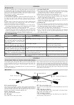
Page 658: ...LEFT TIP TANK Figure 11 67 Tip Tanks 3F17 Issued 12 29 72 ELECTRICAL SYSTEM...

Page 659: ...0 3 F18 INTENTIONALLYLEFTBLANK...

Page 660: ...LEFT ALT 90 AMP MAIN VOLTAGE REGULATOR FILTER SHUNT Figure 11 68 Alternator System Nonparalleling PIPER TWIN COMANCHE SERVICE MANUAL RIGHTALT ELECTRICAL SYSTEM Issued 12 29 72 3F9 3 F20...

Page 661: ...LEFT ALT ALT 9 AMP RIGHT ALT MAIN VOLTAGE REGULATOR PIPERTWINCOMANCHE SERVICEMANUAL G Figure11 68a Alternator System Nonparalleling ELECTRICALSYSTEM Issued 12 29 72 3F21 3 F22...

Page 662: ...90 AMP LEFT ALT PIPER TWIN COMANCHE SERVICE MANUAL RIGHT 26654Q MASTER SWITCH REGULATOR P33A 20 26654 R LATER AIRPLANES Figure 11 68b Alternator System Paralleling Revised 10 1 98 ELECTRICAL SYSTEM 3...

Page 663: ...L TO GEAR WARNING CIRCUIT LEFT MAIN FUEL SELECTOR SWITCH RIGHTMAIN FUEL SELECTOR SWITCH RIGHTMAIN FUELSENDER r 1 RIGHTAUX FUEL SENDER 1 CAPACITORS MAYORMAY NOTBE NSTALLEJ SEECYL ANDOIL TEMPSCHEMATIC C...

Page 664: ...Figure 11 70 Landing Gear Motor Landing Gear Solenoid Landing Gear Warning Serial Nos 30 2 to 30 1716 inclusive and 30 1718 to 30 1744 inclusive ELECTRICAL SYSTEM Issued 12 29 72 363 3G4...

Page 665: ...CHE SERVICE MANUAL DIMMER RIGHTGEAR LIMIT SWITCH GEARWARNING HORN NOSEGEAR LIMITSWITCH GEARDOWN LIGHT GEARUP LIGHT Figure 11 70a Landing Gear Motor Landing Gear Solenoid Landing Gear Warning Serial No...

Page 666: ...Figure 11 71a Anti Collision Strobe ELECTRICALSYSTEM Issued 12 29 72 3G7...

Page 667: ...PIPERTWINCOMANCHE SERVICEMANUAL Exhaust GasTemperature Figure 11 73 Hour Meter ELECTRICALSYSTEM Issued 12 29 72 3G8...

Page 668: ...PIPER TWINCOMANCHE SERVICEMANUAL Figure 11 74 Flap Motor and Solenoid ELECTRICALSYSTEM Issued 12 29 72 369...

Page 669: ...3G10 INTENTIONALLYLEFTBLANK...

Page 670: ...3611 INTENTIONALLYLEFTBLANK...

Page 671: ...nning the wrong direction is the same as a run away It is possible to experience excessive pilot yoke force in only 3 4 seconds under such conditions 3G12 SECTION XII ELECTRONICS Paragraph Aerofiche G...

Page 672: ...PIPER TWIN COMANCHE SERVICE MANUAL THISPAGEINTENTIONALLY BLANK Revised 10 1 98 ELECTRONICS 3G13...

Page 673: ...PIPER TWIN COMANCHE SERVICE MANUAL THISPAGEINTENTIONALLY BLANK ELECTRONICS Revised 10 1 98 3G14...

Page 674: ...PIPER TWIN COMANCHE SERVICE MANUAL THIS PAGEINTENTIONALLY BLANK Revised 10 1 98 ELECTRONICS 3G15...

Page 675: ...nnect the whip antenna cableat the transmitter d Removethe rear mounting bracket and removethe transmitter from the airplane e Remove and keep the four screwssecuringthe transmitter s plain end cap Ca...

Page 676: ...s With this in mind it is advisable to notify your localcontrol tower etc of your intentions to test the locator transmitter before doingso and to keep your test transmissionto a minimalduration a Rem...

Page 677: ...nctioning properly should emit a characteristicdownward swept tone e When the test is completed reposition the ON ARM OFF switch from the OFF position to the ARMposition and reinstall the switch guard...

Page 678: ...o the bottom of the circuit board i Reinsert the control head section into the battery pack being careful not to replace the four screws If the four holes do not line up rotate the battery pack 180 j...

Page 679: ...CH PUPS OUT OF CHANNEL N AND DOWN SET ON OFF ARM SWITCH TO ON PIN STOP i VIEW C Figure 12 1 ELT Portable Folding Antenna Narco CONTACT SEPARATOR PORTABLE ANTENNA CONTACT FINGER NOTCH FOR HANDLE RELEAS...

Page 680: ...Collins General Aviation Division Rockwell International Cedar Rapids Iowa 52406 319 395 3625 Telex 464 421 Edo Corporation Avionics Division Box 610 Municipal Airport Mineral Wells Texas 76067 817 3...

Page 681: ...led out on the Master Parts Price List Aerofiche published monthly by Piper Consult the aircrafts parts catalog for replacement parts NAME AutoControl 1 11 AltiMatic I II AutoControl III and AltiMatic...

Page 682: ...PIPER TWIN COMANCHESERVICEMANUAL THISPAGEINTENTIONALLY BLANK Revised 10 1 98 ELECTRONICS 3G23...

Page 683: ...PIPER TWIN COMANCHE SERVICE MANUAL GRIDS3G24THRU3L24 INTENTIONALLY BLANK 0 S ELECTRONICS Revised 10 1 98 3G24...

Page 684: ...AIRPLANE SERVICE MANUAL CARD 4OF4 TWINCOMANCHE PA 30 PA 39 PIPER AIRCRAFT CORPORATION PIPER PART NUMBER 753645 REVISED OCT 1 1998 4A1...

Page 685: ...Publishedby TechnicalPublications The New Piper Aircraft Inc 2926PiperDrive VeroBeach Florida 32960 U S A 0 GAMA Member GeneralAviation Manufacturers Association 0 4A2...

Page 686: ...be kept current by revisions distributed periodically These revisions will supersede all previous revisions and will be complete Aerofiche card replacements and shall supersede Aerofiche cards of the...

Page 687: ...ualgenerallydoes not containhardwarecalloutsfor installation Hardwarecalloutsare only indicatedwherea specialapplicationis required Toconfirmthe correcthardwareused referto the PA 30 39TwinComanchePar...

Page 688: ...A9 VIII VIIIA IX POWER PLANT NORMALLYASPIRATED POWER PLANT TURBOCHARGED FUEL SYSTEM 2D18 2G1 2121 X INSTRUMENTS 2K14 AEROFICHE CARD NO 3 XI ELECTRICAL SYSTEM 3A9 XII ELECTRONICS 3G12 AEROFICHE CARD NO...

Page 689: ...bustion Air Blower 4C7 13 16 Diagrammatic Cutawayof Heaterto ShowWhirling FlameAction 4C9 13 17 FuelRegulatorandShutoffValve 4C10 13 18 TopView DuctSwitch 4C10 13 19 WiringDiagram 4CII 13 20 PrimaryPo...

Page 690: ...V I vnI 1 LIST OF ILLUSTRATIONS PART II Balancing Stabilator Stabilator Rigging Tool Interconnecting Control Cable Installation Checking Stabilator Friction Magneto Timing Marks Engine Timing Marks Ma...

Page 691: ...cling Switch 4A24 13 15 Systems 4B 1 13 16 Fuel System 4B1 13 17 Fuel Control Valve 4B1 13 18 Combustion Air System 4B1 13 19 VentilatingAir System 4B1 13 20 Electrical System 4B2 13 21 Flame Detector...

Page 692: ...r 4B 14 Standpipe and Preheat Resistor 4B14 Igniter 4B 14 Combustion AirMotor 4B14 Heat Exchanger 4B15 Ventilating AirBlower 4B15 Inspection Cleaningand Repair 4B 16 Heat Exchanger 4B16 Fuel Control V...

Page 693: ...y 4C20 13 103 Cycling Switch and Limit Overheat Switch 4C20 13 104 Combustion Air Pressure Switch 4C21 13 105 Fuel Regulator and Shutoff Valve 4C22 13 106 Duct Switch 4C22 13 107 Overhaul Instructions...

Page 694: ...PIPERTWIN COMANCHESERVICEMANUAL THISPAGEINTENTIONALLY BLANK Revised 10 1 98 HEATING AND VENTILATING 4All...

Page 695: ...cowl The heater uses gasolinefrom the fuel injector on the right engine Therefore anytime the right fuel selector is off the heater is inoperative In case of right engine failure the heater can be ope...

Page 696: ...2 6 PIPER TWIN COMANCHE SERVICE MANUAL 1832 Figure 13 1 Heating and Ventilating System Senal Nos 30 1 to 30 401 incl Issued 12 29 72 4A13 HEATING AND VENTILATING...

Page 697: ...2 PIPER TWIN COMANCHESERVICE MANUAL Figure 13 2 Heating and Ventilating System Serial Nos 30 402 to 30 852 30 854 to 30 901 incl Issued 12 29 7214 4A14 HEATING AND VENTILATING...

Page 698: ...ESH AIR INLET 2 FRESM AIR OUTLET 3 HEATER INLET 4 HEATER OUTLET 5 DEFROSTER INLET 6 DEFROSTER OUTLET 7 CABII EXHAUST AIR OUTLET S CABIN AIR AND DEFROSTER CONTROLS 9 AIR DISTRIBUTOR BOX Figure 13 3 Hea...

Page 699: ...ed below the right and left corners of the instrument panel There is a dump valve arrangement in the heater bonnet to exhaust excessive heat thereby making it possible to operate the heater with all c...

Page 700: ...OF HEATERAND HEATERCOMPONENTS a Inspect all fuel lines and fittings for fuel stains indicating leakage Replace linesor tighten fittingsas necessary b Checkheater for cracks loose bolts screwsand wiri...

Page 701: ...PIPER TWIN COMANCHESERVICE MANUAL Figure 13 4 Heater Installation South Wind Serial Nos 30 1 to 30 401 incl Issued 12 29 72 4A18 HEATING AND VENTILATING...

Page 702: ...nected connect the cabin heat hoses 6 7 defroster cable 1 and hot airdump hose 12 on the air distribution box and secure withclamps j Connect the electrical leads to the terminal block of the heater a...

Page 703: ...PIPER TWIN COMANCHE SERVICE MANUAL Figure 13 5 Flow System South Wind Heater Issued 12 29 72 HEATING AND VENTILATING 4A20...

Page 704: ...heat exchangerand out the exhaust tube After combustion starts the igniter and fuel preheater are turned off by the flame detector switch Refer to Figure13 7 whichalso turns on the ventilatingair blow...

Page 705: ...ANCHE SERVICE MANUAL 0 SAFETY VALV TO IATTERl CIRCUIT BREIER OR USE NOTE FlI e Detector Swltch Shown In Colo or START Posltlon Figure 13 7 Issued 12 29 72 Wiring Diagram for South Wind Heater Model 94...

Page 706: ...ts the shut off solenoid is energized and opens a bypass through which fuel then flows to the heater Gasoline will continue to flow through this system until the heater is turnedoff The chamber behind...

Page 707: ...ns that the heater must shut down if combustion air flow is reversed since the heaterwill operate safelyunder any other combustion air flow condition The special purpose of the thermal fuse is to shut...

Page 708: ...e shut off solenoid is closed or unenergized no fuel can enter the standpipe and the heater is completely shut off When the shut off solenoid is energized fuel flows through the low heat metering orif...

Page 709: ...ro switch A leaf spring between the rod and plunger is provided to maintain a pressure through the rod against the end of the tube When installed on the heater the hollow probe extends into the interi...

Page 710: ...the relay and the flame detector switch and the blower start The combustion air blower continues to run since it obtains its energy from the center terminal of the flame detector switch Electnc energ...

Page 711: ...blowers stop The fuel safetyvalve so lenoid is also de energizedand will not openagain until the flame detector switch becomes heated on another starting cycle TECHNICAL DATA Electrical Requirements...

Page 712: ...are specially designed to permit unit replacement and this type of maintenance is recommended for field service personnel a Ventilating air blower b Flame detector switch c Fuel control valve d Ignit...

Page 713: ...disassem bled for repair Refer to TABLE XIII L 13 31 EXTERNAL CAUSES OF TROUBLE 13 32 ELECTRICAL CHECK a Check voltage at the fuse or circuit breaker through the heater switch and at terminal No 3 of...

Page 714: ...e combustion air tube or an installation defect which prevents the combustion air blower from obtaining a sufficient amount of air Always check these external causes before changing the combustion air...

Page 715: ...ion air and 3 ignition If the combustionair blowerstarts when the heateris turned on the combustion air requirement is satisfied and the thermal fuse and lockout overheat switch are also eliminated as...

Page 716: ...e heater control system The elements which affect heater operation after starting are as follows a Starting safety devices b Fuel control components c The combustion air supply 13 39 STARTING SAFETY D...

Page 717: ...the trouble is not caused by restriction replace the combustion air motor NOTE The combustion air blower must not be subjected to excessive ram airpressures The blower needs about I to 2 inches of wat...

Page 718: ...PIPER TWIN COMANCHESERVICE MANUAL AIR INLET AOAPTER Figure 13 10 Exploded Parts View Heater Assembly HEATING AND VENTILATING Issued 12 29 72 4 B11...

Page 719: ...ing NOTE The combustion air inlet adapter and shroud adapter may remain in the airplane when the heater is re moved If attached to the heater they may have other installation parts welded or clamped t...

Page 720: ...heater housing Remove the guard and relay as an assembly on heat ers so equipped d On heaters equipped with the relay 25 remove the nut 26 and lockwasher 27 to free the relay ground wire and relay ass...

Page 721: ...he standpipe by backing off the smaller hex which is welded to the pipe When the threads are clear the standpipe 69 and preheat resistor 73 can be lifted out through the opening in the heater housing...

Page 722: ...ILATING AIR BLOWER Refer to Figure 13 11 a Remove the screw 1 and lockwasher 2 from the end of the motor 7 to free the motor from the ground strap b Remove the three screws 3 washers 4 grommets 5 ands...

Page 723: ...on residue from inside heat exchanger by soaking this as sembly in a20 byweightsolutionof ammoniumacetateat atemperatureof 180F for a period of 5 to 10 hours Flush out exchanger with water after clean...

Page 724: ...otor and pull the end bell 3 off far enough to permit unsoldering of the capacitor lead from the eyelet on the brush holder insulator Remove the end bell 3 b Remove the two nuts 12 from the other end...

Page 725: ...rush holders The 718855 springs must be used with 1 4 x 3 8 brushesand the717472 springs with 1 4x 1 4 brushes Make sure that stator leads and capacitor lead are securely soldered j No specific test o...

Page 726: ...SY 10 BRUSH ANDCUPASSY 11 BRUSH 12 BRUSH SPRING 2 REQ 13 BEARING 2 REQ 14 SNAPRING 15 ROTOR ASSY 16 STATOR ASSY 17 LOAD SPRING 2 REQ 16 13 1 SCREW 2 REQ 2 NUT 2REQ 3 LOCKWASHER 2 REQ 4 ENDBELL 5 ENDBE...

Page 727: ...tch just clicks again to determine point of transfer then turn the screw exactly 3 4 turn past the trans fer point g Hold the screws and tighten microswitch mounting nuts to lock switch se curely in p...

Page 728: ...cloth dampened in cleaning solvent Do not disassemble or attempt to repair this unit c Replace safety valve if found defective 13 68 WIRING a Inspect all heater wiring for condition of insulation and...

Page 729: ...the heat exchanger 87 using a new gasket 81 and tighten with a 13 16 inch deep socket Reinstall the screw 77 to connect the igniter ground wire attaching one end of the bonding strap 76 with the same...

Page 730: ...nstalling the four screws 31 Also reinstall the relay 25 by installing the lockwasher on the relay stud inside the guard then the relay ground wire and the lockwasher nut 26 Tighten nut securely to ob...

Page 731: ...lude the following components a A suitable cradle or bracket for mounting the heater with provision to dis pose of the exhaust gases b A source of 12 volts DC This should be a variable source from a t...

Page 732: ...s at once Allow fuel to flow through the valve for a few seconds then de energize both solenoids One or two drops of fuel may fall from the outlet within 15 seconds after the so lenoids are closed Aft...

Page 733: ...operly if the heater burns nor mally and did not have an excessive deposit ofcarbon in the exhaust tube or com bustion chamber when cleaned during overhaul Speed of the ventilating air blow er is not...

Page 734: ...con nections Replace blower Replace fuse Replace switch Replace switch Blower runs when switch is in HEAT position but heater will not ignite No fuel pressure Defective igniter Check fuel supply Repla...

Page 735: ...R cont Remedy Remove restriction Replace switch Replace Replace valve relay Defective fuel control valve Restricted ventilating air flow Defective cycling overheat switch Defective cycling switch Defe...

Page 736: ...RT SOUTH WINDHEATER cont Trouble Cause Remedy Heater smokes exces sively Leaking fuel control valve Replace valve Slow combustion air motor Defective installation Replace motor Correct supply combusti...

Page 737: ...the bot tom panel of the nose section h Disconnect the air inlet hose 12 from the forward end of the heater by re leasing the hose attachment clamps i Disconnect the combustionair blower inlet hose 13...

Page 738: ...ROUD 10 FUELSUPPLY LINE 11 FUEL DRAIN TUBE 12 AIR INLET HOSE 13 COMBUSTION AIR INLET HOSE 14 HEATER CLAMPS 15 HEATER CONTROLSWITCH 16 SLEEVE 17 LIMIT SWITCH 18 CYCLING SWITCH 19 PRESSURESWITCH 20 IGNI...

Page 739: ...access panel 13 83 DESCRIPTION OF HEATER AND BASICCOMPONENTS 13 84 SPARK SPRAY IGNITION Refer to Figure 13 16 The controlled at omized spray from a specially designed spray nozzle coupled with high vo...

Page 740: ...requirements with inlet pressures up to 50 psi The shutoff valve is operated by a solenoid 13 86 DUCT SWITCH Refer to Figure 13 18 This switch is installed in the ventilating air duct downstream from...

Page 741: ...during flight 13 88 VENTILATING AIR BLOWER This blower is attached to the inlet end of the heater assembly and provides a source of ventilating air through the heater Ram air from the ventilating air...

Page 742: ...HEATER SWITCHis connected in the line that supplies electrical power to all heater equipment and controls When this switch is in the OFF position the entire heater system is inoperative This switch h...

Page 743: ...tion turn OFF the HEATER SWITCH 13 91 MAINTENANCE SERVICE Instructions contained in this section consist of periodic inspection adjustments and minor corrections required at normal designated interval...

Page 744: ...loration of the sheath g Inspect the combustion air blower assembly for security of mounting and security of connecting tubing and wiring Tighten any loose electrical terminals and air tube connection...

Page 745: ...g locations Refer to Figure 13 20 1 Terminal No 6 on the heater terminal strip 2 From terminal No 6 of the heater terminal strip through the radio noise filter to the ventilating air motor 3 Electrica...

Page 746: ...cribed above except that power is now supplied through the HEAT side of the HEATER SWITCH 1 Terminal No 1 of the heater terminal strip 2 From terminal No 1 of the heater terminal strip through the rad...

Page 747: ...nnect wire at quick disconnect terminal 2 Disconnect the inlet tubing from the inlet air adapter 3 Loosen the clamps that hold the combustion air blower assembly in the support bracket and slide the m...

Page 748: ...e blower inlet adapter in the same orientation as before re moval 3 Place the combustion air blower assembly in position in the attaching clamp so the air tubing can be connected and slide the tubing...

Page 749: ...airplane type spark plug cleaner except that it will be necessary to use two or more adapters in order to raise the long extension of the plug far enough out of the cleaner nozzle opening to perform a...

Page 750: ...pounds 4 Install the grommet 23 Figure 13 25 in the heater jacket opening 5 Carefully insert the spring connector on the high voltage lead into the spark plug shell press down gently and start the nu...

Page 751: ...voltage lead to the spark plug Refer to Paragraph 13 100 c 4 Connect the primary lead 5 to the primary terminalon the ignition unit 18 and tighten the nut securely 5 Check for proper heater operation...

Page 752: ...disassembly Refer to wiringdiagram Figure 13 19 13 104 COMBUSTION AIR PRESSURESWITCH Refer to Figure 13 25 a Removal 1 Disconnect electrical leads from the terminals of the combustion air pressure sw...

Page 753: ...TCH Refer to Figure 13 26 a Removal 1 Disconnect the electrical leads from the terminals on the exposed face of the switch and mark to facilitate installation 2 Remove the two attaching screws and was...

Page 754: ...4 C23 INTENTIONALLYLEFTBLANK...

Page 755: ...4C24 INTENTIONALLY LEFT BLANK...

Page 756: ...harness assembly intact First disconnect wires at terminal strip and components The ventilating air blower housing must be removed so that the two motor wires and solenoid valve quick disconnect con n...

Page 757: ...d while holding the fuel tube fitting at the jacket remove the re ducing bushing adapter 42 Then with 3 4 inch deep socket remove the nut 44 fuel fitting shroud 43 and gasket 46 n Remove the two screw...

Page 758: ...b Remove the outlet adapter 5 byremoving the two screws 6 and lockwash ers 7 c Remove the inlet flange 8 byremoving the three screws 9 and lockwash ers 10 d Remove screws 12 and 16 and lockwashers 13...

Page 759: ...nt on the surface in certain areas This con dition does not require replacement of the combustion tube assembly unless se vere overheating has produced soft spots in the metal NOTE This assembly shoul...

Page 760: ...85 b Inspect all wires and wiring harnesses for damage to insulation damaged terminals chafed orcrackedinsulationand brokenplastic bands Individualwires can be replaced by making up new wires from No...

Page 761: ...eads to a 12 volt battery to open the solenoid valve The conical angle spray pattern should be even and dispersed the same in all directions Exercise caution to keep at omized fuel away from fire k In...

Page 762: ...ombustion air motors b Test the combustion tube assembly 86 for leaks as follows 1 Fashion a sealing plate from approximately 1 8 inch tiuck flat stock to seal the nozzle holder opening in the combust...

Page 763: ...MBUSTION TUBE ASSEMBLY c Test the combustion air pressure switch as follows 1 Connect an adjustable air pressure line that can be controlled in a range of zero to 5 0 psi maximum of water to the switc...

Page 764: ...el feedandnozzleholderassemblymustbereplaced e Spraytestthenozzle see 83 Figure13 25 as follows 1 Installthenozzleinthe fuelfeedandnozzleholderassemblyandconnectthefuel tubeto a 7 psi fuelpressuresour...

Page 765: ...otor shaftand rotateit until the set screwis alignedwiththe flat sideof the motor shaft Tightentheset screwjusttightenoughtoholditat thistime c Attach the capacitor and leads assembly 61 to the motorb...

Page 766: ...18 PIPER TWIN COMANCHE SERVICE MANUAL 15 Figure 13 25 Exploded View of Heater Assembly No 751 959 HEATING AND VENTILATING Issued 12 29 72 4o1...

Page 767: ...Figure 13 25 I HEATER ASSEMBLT 2 PLATE lOENTIFICATION 4 SCREW AN3Sao 0 S WiNR AlSEMBLY ICNITIOS TO FILTI 6 WIRS ASSEMBLY SLOWER GOUNO 7 WIRK ASSEMBLY NEATER OUND i WIRE ASIMBLY TlEMINAL I TO OVERHEAT...

Page 768: ...et Exercise care to clear the pressure switch tube in the exhaust outlet and see that the rope gasket 85 is properly located Close the gap on the jacket assembly and install screws 88 89 and 90 and lo...

Page 769: ...ttingshroudgasket 46 and shroud 43 on the fuel fitting and install the nut 44 finger tight Insert a 3 4 inch open end wrench inside the jacket and hold the fuel tube fitting while tightening the nut 4...

Page 770: ...ND MOTOR ASSEMBLY 2 ADAPTERASSEMBLY BLOWERINLET 3 MOUNT COMBUSTION AIR BLOWER SUPPORT 4 COMBUSTIONAIR BLOWERAND MOTOR 5 ADAPTER OUTLET Figure 13 26 Exploded View Combustion Air Blower and Motor Assemb...

Page 771: ...heck then apply prop er voltage to run motor and recheck for proper clearance g Slide the blower outlet adapter 5 on the blower housing outlet 15 and in stall the two screws 6 and lockwashers 7 13 117...

Page 772: ...the same diameter as the heater being tested A 2 25 inch diameter orifice should be centrally located at the outlet end An aperarure should beprovided for the thermometer and duct switch and a static...

Page 773: ...erference If either blower fails to run locate and correct the trouble before proceeding with the test f Connect a voltmeter from open side of combustion air pressure switch ter minal to ground to det...

Page 774: ...f the duct switch to make it inop erative and observe action of the cycling switch When micro override switch is installed move the heat control to the full high position The cycling switch should cyc...

Page 775: ...ible damage d If any part of the stem assembly 2 is damaged or if the cap nut 6 is not drilled for safetying purposes replace the assembly e Reassemble the unit and tighten the cap nut 6 tight enough...

Page 776: ...eak er Apply external power supply Attempt to start heater Refer to paragraph 13 89 Turn on manual shutoff valve or master sole noid Check for low pressure or replace regulator Refer to paragraph 13 1...

Page 777: ...Press reset button firm ly and recheck to deter mine reason for switch opening Check for low blower output due to low volt age and correct it If switch is defective re place it Refer to paragraph 13...

Page 778: ...replace motor Refer to paragraph 13 108 1 and r thru u 13 115 b thru g Replace filter Combustion air blower fails to run Faulty wiring to motor Inspect and replace faulty wiring Poor ground connectio...

Page 779: ...shut off valve solenoid valve and fuel lines Make necessary re pairs Spark plug partially fouled Loose primary con nection at ignition assembly Faulty vibrator Combustion air blower speed fluctuates...

Page 780: ...n replace ig nition assembly only Refer to paragraph 13 102 Remove nozzle for cleaning or replace ment Refer to para graphs 13 108 m and n 13 112 i and 13 115 k and 1 Tighten or replace the nozzle as...

Page 781: ...Refer to paragraph 13 103 Low voltage Attach external power Heater fails to shut off Fuel solenoid valve in heater stuck open Remove and replace solenoid assembly Refer to paragraphs 13 108 q 13 112...

Page 782: ...4 E3 INTENTIONALLYLEFTBLANK...

Page 783: ...4 E4 INTENTIONALLYLEFTBLANK...

Page 784: ...4 E5 INTENTIONALLYLEFTBLANK...

Page 785: ...4E6 INTENTIONALLYLEFTBLANK...

Page 786: ...f Pressure Gauge 14 16 Removal of Outlets 14 17 Installation of Outlets 14 18 Purging Oxygen System 14 19 Cleaning of Face Masks EngineSynchrophaser 14 21 Description of Synchrophaser System 14 22 Sys...

Page 787: ...is airplane and are not covered in other sections of this Service Manual This information provides instructions for remedying difficulties which may arise in any of the accessories and the instruction...

Page 788: ...30 852 incl 30 854 to 30 901 incl PIPER TWIN COMANCHESERVICE MANUAL 1924 1 CONTROL CABLE 2 OUTLETS 3 LOW PRESSURE LINES 4 PRESSURE GAUGE 5 HIGH PRESSURE LINES 6 OXYGEN CYLINDER 7 CLAMPS 8 FILLER VALVE...

Page 789: ...OW PRESSURE LINES 4 PRESSURE GAUGE 5 HIGH PRESSURE LINES 6 OXYGENCYLINDER 7 CLAMPS 8 FILLER VALVE 9 REGULATOR Figure 14 2 Oxygen System Installation Serial Nos 30 853 30 902 to 30 1716 incl and 30 171...

Page 790: ...E 2 OUTLETS 3 LOW PRESSURE 4 PRESSURE GAUGE 5 HIGH PRESSURE LINES 6 OXYGEN CYLINDER 7 CLAMPS 8 FILLER VALVE 9 REGULATOR Figure 14 3 Oxygen System Installation Serial Nos 30 1717 30 1745 to 30 2000 inc...

Page 791: ...haulbe conductedby an FAAApprovedStationor themanufacturer ScottAviation The followingchecksandchart givesrecommended inspectionandoverhaultimefor thevariouspartsofthe oxygensystem a Theoxygencylinder...

Page 792: ...f the total supply per 24 hour period All traces of the detector fluid should be wipedoff at the conclusionof the examination 14 8 MAINTENANCE a Check that all lines have sufficient clearancebetween a...

Page 793: ...s condition shall be determined as follows a Evaporate 100 milliliters of the liquid to dryness in a weighed glass dish Evaporation may be accomplished by heating at 200 F for one half hour b After ev...

Page 794: ...e Install access panel on the rear wall of the baggage area 14 12 REMOVALOF FILLER VALVE a In airplanes with Serial Nos 30 to 30 852 inclusive and 30 854to 30 901 inclusive remove the access panel fro...

Page 795: ...Connect the outlet to the low pressure line c Position the trim panel and secure with screws d Position the outer half outlet and secure with a suitable spanner wrench e Torque the fittings into the...

Page 796: ...the sides of the breathing bag donotstick together while drying as this may decrease the life of the rubber in the bag The mask can be steril ized with a solution of 70 percent ethyl alcohol TABLE XI...

Page 797: ...AY BE SLIT TO FIT OVER TUBING SECURE WITH MS3367 CABLETIES POSITION SLIT AWAY FROM WIRES ECT PIPER TWIN COMANCHE SERVICE MANUAL Figure 14 3a Oxygen Tubing Installations Added 10 28 82 ACCESSORIES AND...

Page 798: ...In the manual position enginesand propellers are operated and controlled in the conventional manner After manually synchronizing engines the selector switch can be set to the phaseposition This permit...

Page 799: ...the meterjack on the front panel of computer amplifier Refer to Figure 14 8 Usea suitable cable and 1 4inch phoneplugto connect to the computer NOTE When fabricating this test box it is advisable to...

Page 800: ...TENGINE 7 EXISTINGTACHOMETER SHAFT 8 STROBESENSOR 9 INSTRUMENTPANEL 10 WIRE HARNESS 11 DUAL DRIVE ADAPTER LEFTENGINE 12 EXISTINGTACHOMETERSHAFT 13 FIREWALL 14 NACELLE BULKHEADS 15 PULSE GENERATOR 16 S...

Page 801: ...HTenginewith the use of the starter to a position that will cause the zero center reading voltmeter to deflect to left of center A full deflection to left must cause a slow amperage decrease to 0 amps...

Page 802: ...tion Lubricate witha suitableHighTemperatureGrease 2 The retainer clip on the driveend of the tach cableis not chafingagainstthe bell housing No signsof chafingshould be evident 3 The squareends of th...

Page 803: ...of the small plug attached to the computer should be approximately 200 ohms i Check the direction of the pulse generator by operating it from both ends and observeif lights in the strobe sensorillumi...

Page 804: ...ed to the light they are inoperativeand must be replaced d Connect the strobe sensor simulator Refer to Figure 14 11 Move the potentiometer and listen to the computer The motor should run at approxima...

Page 805: ...ensor into the mounting STROBE SENSOR Refer to Figure gbracket located on the inboardside of the longitudinal bulkhead and secure loosely with the clamp NOTE The front end of the strobe sensor can be...

Page 806: ...n stroke Listen for an audiblemagnetoimpulse click e Place a pencil line on the spinner adjacent to the nose cowl split line or mark the gear tooth that isadjacent to the timingmark on the starter hou...

Page 807: ...f the outboard longitudinal bulkhead c Loosen the knurled nuts which secure the tach shafts to the front and rear of the pulsegenerator and slide the tach shafts out of the unit d Disconnectthe electr...

Page 808: ...oke The slave engine is then set at the desired propeller position cylinder number and ignition stroke This is predetermined at the factory and is different for each model aircraft h Connect the tach...

Page 809: ...urning at near cruisingRPM A pulsegenerator simulatormay be used accordingto paragraph14 24 and Figure 14 13 d If either of the glowlampsis inoperative the red colored block that holds the lamps must...

Page 810: ...NOTE NOT VOLTAGE SENSITIVE Figure14 8 Fabricated Test Box PLI A A CC MS PHOTO CONDUCTORS Figure 14 9 ElectricalSchematic ACCESSORIES AND UTILITIES Issued 12 29 72 4F7...

Page 811: ...R PHOTO CONDUCTOR NOTE NOT VOLTAGE SENSITIVE Figure14 10 Strobe Sensor Internal WiringTest Unit POT MOTORSTARTS AT APPROX 7 0 VOLTS JUSTAT STARTOF MOTOR PRESSUREOR DRAINSHOULD READ 05 FOR SLOT DISK 10...

Page 812: ...Test Terminal A228 PULSE GENERATOR SIMULATOR APPROX 1200 R P M 01 UNIJUNCTIONTRANSISTOR MOTOROLA HEP 310 RI 39k 1 2 W IO RES R2 330A 1 2W IORES R3 200 1 2 W IO RES ADJUSTR4 FORPULSE AMPLITUDE OF 1 5 V...

Page 813: ...ulty Pulsegeneratorand glowlamp amplifier incomputer not operating Glowlamp or lamps and or photo con ductor or conductors defective Faulty computer Visuallycheck tach shafts Perform electrical test i...

Page 814: ...PIPER TWIN COMANCHESERVICEMANUAL THISPAGEINTENTIONALLY BLANK Revised 10 1 98 ACCESSORIES AND UTILITIES 4F11...

Page 815: ...PIPER TWIN COMANCHE SERVICE MANUAL GRIDS4F12THRU4G2 INTENTIONALLY BLANK ACCESSORIES ANDUTILITIES Revised 10 1198 4F12...

Page 816: ...PIPER TWIN COMANCHE SERVICE MANUAL THISPAGEINTENTIONALLY BLANK Revised 10 1 98 INTRODUCTON PA 39 ONLY 4G3...

Page 817: ...39 model only Information common to both PA 30 and PA 39 models is in Part I When service information in Part I does not specifically callout PA 39 but is broken down by PA 30 serial numbers only use...

Page 818: ...ription 1 3 Fuselage 1 4 Wing 1 5 Empennage 1 6 Flight Controls 1 7 Landing Gear 1 8 Brake System 1 9 EnginesandPropellers 1 10 Fuel System 1 11 Instruments 1 12 Electronic Equipment 1 13 Heating and...

Page 819: ...ction thecabin section andthe tail conesection 1 4 WING The laminarflow wing is of all metalstressed skin full cantileverdesign consistingof two wingpanelsboltedtogetherat thecenterof thefuselage Thew...

Page 820: ...HC E2YL 2 HC E2YL 2S HC E2YL 2SF HC E2YL 2BL HC E2YL 2BLS HC E2YL 2BLSF 160 160 100 130 100 130 1 10 FUEL SYSTEM The fuel system consists of four rubber type cells located in the wings with a total f...

Page 821: ...PIPER TWIN COMANCHESERVICEMANUAL THIS PAGEINTENTIONALLY BLANK INTRODUCTON PA 39 ONLY Revised 10 1 98 4G8...

Page 822: ...PIPER TWIN COMANCHESERVICEMANUAL PARTII SECTIONII HANDLINGANDSERVICING Issued 12 29 72 HANDLING ANDSERVICING PA 39 ONLY 4G9...

Page 823: ...ty Oil Consumption Maximum Fuel Aviation Grade Minimum Octane Fuel Injector Bendix Magneto 2 Scintilla Magneto Drive Ratio to Crankshaft Magneto Drive Rotation Magneto Timing Magneto Point Clearance L...

Page 824: ...tio FuelPump SR 88D 171 REM 40E REB 37N 0 018to0 022in 0 015to0 021 in 1 3 24 1 4 2 3 0 5 1 Clockwise Counterclockwise Model MZ4206 MZ4216 13 55 1 Counterclockwise Clockwise 12 volt ALX 8403 VSF 7203...

Page 825: ...s Two 15U S gallons Type ShockStrutType FluidRequired Struts Brakes StrutExtension StaticLoad MaximumAirPressure Strut Tread Widthfromeachtire center WheelBase NoseWheelTravel MainWheelToe In TurningR...

Page 826: ...2 875 in 4 ft 6 in 11 5 in FUSELAGE Length Including TailCone Fairing Width Without Stabilator Height Without VerticalFin WINGS 23ft 0 950in 47 875in 53 875in d Span Width 35 ft 11 75 in 36 ft 9 625...

Page 827: ...rbo AS TotalWingArea IncludingAileron andFlaps 178sq ft Aileron 14 1sq ft Flap 20 2 sq ft Stabilator includingtrimtab 32 5sq ft Fin 9 0sq ft Rudder 5 9 sq ft CONTROL SURFACES TRAVEL Referto TableV l P...

Page 828: ...PIPER TWIN COMANCHE SERVICE MANUAL THIS PAGEINTENTIONALLY BLANK Revised 10 1 98 HANDLING AND SERVICING PA 39 ONLY 4G15...

Page 829: ...COMANCHE SERVICE MANUAL PARTII SECTIONIV STRUCTURES Paragraph Aerofiche Grid No 4G17 4 1 Checking and Balancing Stabilator NOTE Refer to Part I for Rudder and Aileron 0 STRUCTURES PA 39ONLY Revised 6...

Page 830: ...to the fuselage should be loosened and tightened finger tight during balancing After balancing is completed stabilator bearing block bolts should be torqued to a value of 135to 140 inch pounds Ascerta...

Page 831: ...pring scale should be removed and theplates should be distributed equally on both sides of the stabilator balance tube and the bolt secured f All stabilator and tab controls should be reconnected g Th...

Page 832: ...URFACECONTROLS Rigging and Adjustment of Stabilator Controls Adjustment of Interconnecting Control Cables Checking Stabilator Frictional Resistance Aerofiche Grid No Paragraph 5 1 5 2 5 3 4G20 4G23 4G...

Page 833: ...he protractor is centered NOTE The stabilator should contact both of its stops before the control wheel contacts its stops 3 Set on the protractor the number of degrees down travel as given in Table V...

Page 834: ...osition 130 aft vertical Neutral to Fwd Neutral to Aft Cable Tension Aileron Stabilator Stabilator Trim Tab Rudder Rudder Trim 26 lbs 20 18 Ibs 20 12 lbs 20 25 ibs to 40 Ibs 10 lbs 20 3 51 in 3 51 in...

Page 835: ...eutral fore and aft and the control cable tension is correct as required in Table V I Neutral position of the control wheel is 7 88 inches from the metallic surface of the instrument panel as measured...

Page 836: ...he springs 18 and 25 have 0 06 inch extension with ailerons and rudder in neutral positioning g If necessary the left interconnecting spring 25 extension may be increased up to a maximum of 0 38 inch...

Page 837: ...9 PULLEY ASSEMBLY LEFT 10 INTERCONNECrING CABLE LEFT 11 RUDDER CABLE LEFT 12 CONTROL CABLE PULLEY CLUSTER 13 TURNBUCKLE RIGHT 14 SPRING IS COTTER PIN 16 BOLTASSEMBLY 17 CLEWS 18 SPRING RIGHT 19 CABLE...

Page 838: ...e averageused inthe frictioncalculationswhichare as follows 1 Todeterminesystemfrictionsubtractpullrelaxingforcefrompullupforce EXAMPLE Pullupforce 25 lbs PullRelaxingforce 5 lbs Systemfriction 20lbs...

Page 839: ...alsystemfrictionasfollows Total System Friction 25 lb max 22 1 2 lb 20 lb Average Down Spring Force 17 lb min 16lb min 15lb min Example If the frictionis 25lb thedownspringmustbeat least 17lb h If sys...

Page 840: ...PIPER TWIN COMANCHESERVICEMANUAL THISPAGEINTENTIONALLY BLANK Revised 10 1 98 SURFACE CONTROLS PA 39 ONLY 4H3...

Page 841: ...PIPER TWIN COMANCHESERVICEMANUAL THISPAGEINTENTIONALLY BLANK SURFACE CONTROLS PA 39 ONLY Revised 10 1 98 4H4...

Page 842: ...RTII SECTIONVIII POWERPLANT NORMALLY ASPIRATED Aerofiche Grid No Paragraph 8 1 8 2 Magneto Timing Procedure Internal Timing 4H6 Magneto InstallationandTimingProcedure Timing Magneto to Engine 4H7 Revi...

Page 843: ...ng drive coupling of S4LN 21 magnetos in the left hand direction and S4RN21 magnetos in the right hand direction until the red or white chamfered tooth on the distributor gear appears through the timi...

Page 844: ...ylindertendingtolift thethumboff the sparkplug hole In this position both valvesof No 1 cylinderare closed Turnthe crankshaft oppositeto its directionof rotationuntil it is approximately35 degreesBTC...

Page 845: ...til it is approximately 35 degrees BTC on compression stroke No I cylinder NOTE The crankshaft should not be rotated more than 10 degrees in the direction opposite rotation from the 25 degrees BTC as...

Page 846: ...ecktimingto makesureit is stillcorrect n Installtheothermagnetoandtimeusingtheprecedinginstructionsa thru 1 o With both magnetos timed to the engine and secured check that they fire together Rotate th...

Page 847: ...Spinner Bulkhead Check Nut Spinner Attachment Screws Required Torque Dry 22 foot pounds 50 foot pounds 40 42 foot pounds 35 40 foot pounds 40 inch pounds CHAMBER PRESSURE REQUIREMENTS WITH TEMPERATUR...

Page 848: ...SECTIONVIIIA POWERPLANT Turbocharged Aerofiche Grid No Paragraph 8A 1 Magneto Timing Procedure Internal Timing 4H12 8A 2 Magneto Installation and Timing Procedure Timing Magneto to Engine 4H13 Revised...

Page 849: ...ive coupling of S4LN 21 magnetos in the left hand direction and S4RN21 magnetos in the right hand direction until the red or white chamfered tooth on the distributor gear appears through the timing in...

Page 850: ...ft the thumb off the spark plug hole In this position both valves of No I cylinder are closed Turn the crankshaft opposite to its direction of rotation until it is approximately 35 degrees BTC on the...

Page 851: ...l it is approximately 35 degrees BTC on compression stroke No I cylinder NOTE The crankshaft should not be rotated more than 10 degrees in the direction opposite rotation from the 25 degrees BTC as th...

Page 852: ...nuts check timing to make sure it is still correct n Install the other magneto and time using the preceding instructions a thru 1 o With both magnetos timed to the engine and secured check that they f...

Page 853: ...PIPER TWIN COMANCHESERVICEMANUAL THISPAGEINTENTIONALLY BLANK POWERPLANT TURBO PA 39 ONLY Revised 10 1 98 4H16...

Page 854: ...PIPER TWIN COMANCHE SERVICE MANUAL PARTII SECTIONX INSTRUMENTS Issued 12 29 72 INSTRUMENTS PA 39 ONLY 4H17...

Page 855: ...ITCH 23 VOLT REG SEL SWITCH 24 NAVLIGHTS 25 RED ANTI COLLISION WHITE ANTI COLLISION 26 27 28 29 30 31 32 33 34 35 36 37 38 39 40 41 42 43 44 45 46 47 48 49 50 PARK BRAKEHANDLE POSTLIGHTSSWITCH LANDING...

Page 856: ...PIPER TWIN COMANCHE SERVICE MANUAL PARTII SECTIONXI ELECTRICALSYSTEM Issued 12 29 72 ELECTRICAL SYSTEM PA 39 ONLY 4H19...

Page 857: ...N UGHT PIPER TWIN COMANCHE SERVICE MANUAL 26654 ANTI COLUSIONAND DOMEUGHT 10 AMP FRONTDOME REARDOME UGHT SWITCH UGHT SWITCH REAR DOME UGHT TO INSTRUMENTUGHTS Figure I1 1 Dome Lights Schematic ELECTRIC...

Page 858: ...PIPER TWIN COMANCHE SERVICE MANUAL 266540 INSTRUMENTLIGHTS 5 AMPS Issued 12 29 72 ELECTRICAL SYSTEM PA 39 ONLY 4H21...

Page 859: ...PIPER TWIN COMANCHESERVICEMANUAL REDANTI COLUSION LIGHT 0 5 AMP REDSTRCBE LIGHTASSEMBLY Figure 11 3 RedStrobe Light Schematic ELECTRICAL SYSTEM PA 39ONLY Revised 10 1 98 4H22...

Page 860: ...PIPER TWIN COMANCHESERVICEMANUAL WHITE ANTI COLLUSION UGHT SAMP Figure 11 4 White Strobe Lights Schematic Issued 12 29 72 ELECTRICAL SYSTEM PA 39 ONLY 4H23...

Page 861: ...PIPER TWIN COMANCHE SERVICE MANUAL 0 THIS PAGEINTENTIONALLY BLANK ELECTRICAL SYSTEM PA 39 ONLY Revised 10 1198 4H24...

Page 862: ...nd AltiMatic III Service Manual Altimatic IIIB 1 Service Manual AutoFlite Service Manual AutoFlite II Service Manual Pitch Trim Service Manual For radio service and maintenance refer to the manufactur...

Page 863: ...PIPER TWIN COMANCHESERVICEMANUAL GRIDS412THRU4L24 INTENTIONALLY BLANK ELECTRONICS PA 39ONLY Revised 10 1 98 412...

Reviews: