


Manual for Stealth M1 v1.0
Page 1
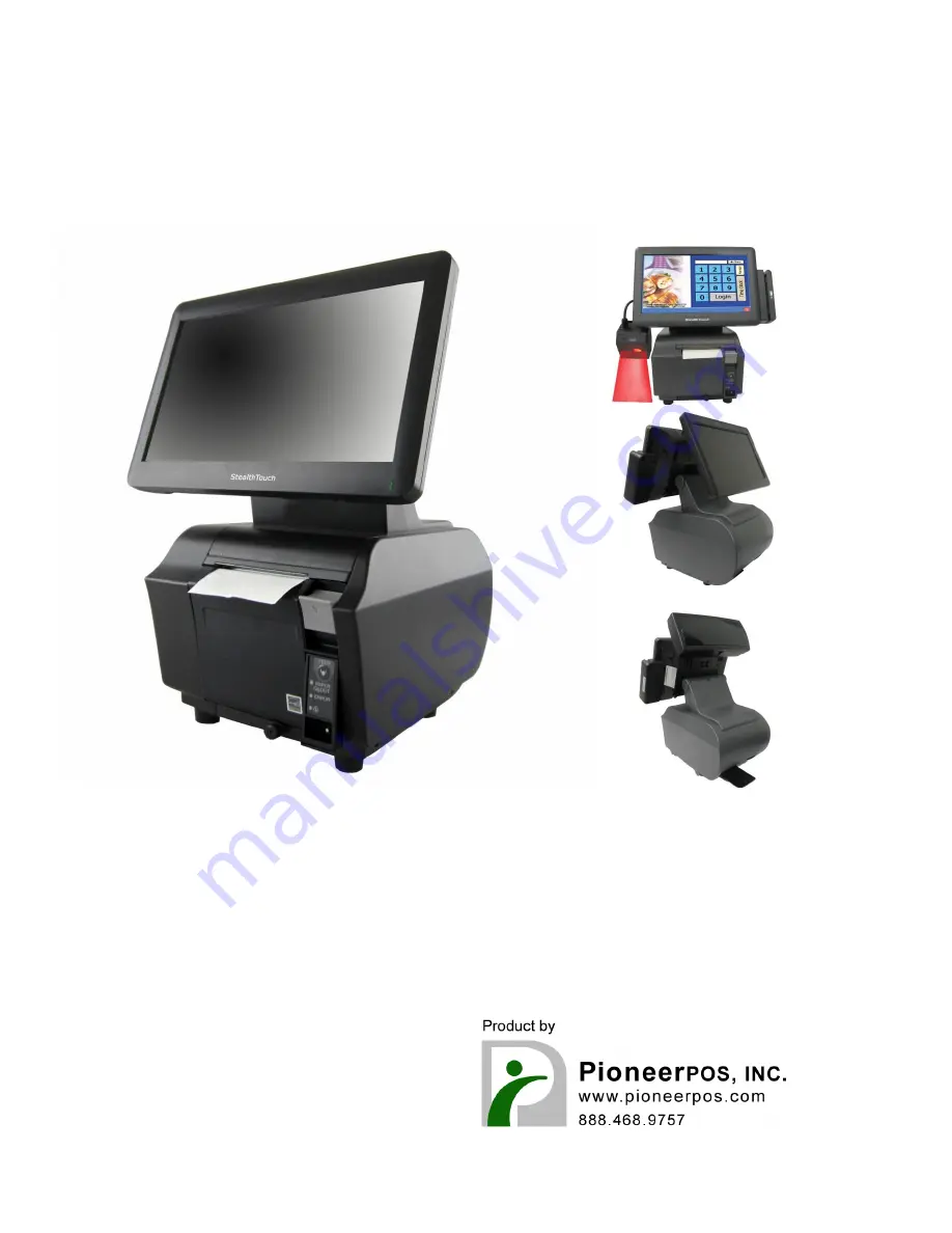
User Manual
Stealth-M1
If you need further assistance, use one of the following:
Web: http://www.pioneerposftp.com
Pioneer POS Support line:
Call: (909) 468-9757
Email: [email protected]
The PIONEERPOS Stealth-M1 comes with a comprehensive User Manual that you can easily download for free from manualshive.com. This manual provides detailed instructions and troubleshooting tips to help you maximize the potential of your Stealth-M1, ensuring a seamless user experience.
Manual for Stealth M1 v1.0
Page 1
User Manual
Stealth-M1
If you need further assistance, use one of the following:
Web: http://www.pioneerposftp.com
Pioneer POS Support line:
Call: (909) 468-9757
Email: [email protected]


