background image

Summary of Contents for T-5101

Page 1: ... fr A7 A I Systematics General l orporation I I rJatiooal I ieotifil laboratories lJivisioo ...

Page 2: ...d Operation Escape Sequences Formatting Aids Data Editing Operation Data Interface Data Transmission Special Function Keys Status Displays Section IV Monitor Description 2 1 2 12 2 23 2 24 2 25 2 25 2 25 2 26 2 27 3 1 3 1 3 3 3 5 3 5 3 6 3 6 3 12 3 12 3 14 3 18 3 18 3 21 3 21 Monitor Electrical Specifications 4 1 Data Display Specifications 4 2 Environmental Specifications 4 3 Human Factors Specif...

Page 3: ...BLE OF CONTENTS cont Paragraph Section VI Scheduled Maintenance Scheduled Maintenance 6 1 Safety Precautions 6 7 Section VII Schematic Drawings and Diagrams 7 1 Section VIII Renewal Parts Information 8 1 ...

Page 4: ...ion Significance Table of Flags Asynchronous Transmitter Receiver Control Tri State Bus Control Keyboard Operation Binary Codes Formatting Aids Absolute Cursor Positioning Block Transmission Control Special Functions Status Displays Input Data Specifications CRT Display Specifications Baud Rate Selections T 5l01 Failure Analysis Guide Logic Board Terminal Identification Chart Tri State Bus Locatio...

Page 5: ...Shields Logic Power Supply Video Enclosure Chassis Cabling Internal Controls CRT Mounting Right Side CRT Mounting Left Side Voltage Waveforms for Display Video Circuit Board Component Location Main Logic Board Layout Program Display 7 1 thru Page 1 2 2 1 2 3 3 2 3 4 3 7 4 5 5 2 5 4 5 5 5 6 5 8 5 9 5 10 5 11 5 14 5 15 5 16 5 12 5 24 5 30 6 6 7 21 Schematics 7 Configuration 7 3 7 22 thru 7 44 Schema...

Page 6: ...I Interactive Display Terminal The scope of the material provided is sufficient in all aspects of operation and maintenance of the equipment The T SIOI consists of cable interconnected assemblies This unit is in turn connected to a computer by an additional interface cable The T 5101 Interface Display Terminal is shown in Figure 1 1 1 1 ...

Page 7: ... FigUl e 1 1 ...

Page 8: ... Protected Fields Reduced Intensity Status Displays 8 Control Characters Display 31 Blinking Field Rate 4 per second Security Fields Display Suppressed Page Roll Up Cursor Format Controls Data Transmission Code Parity Reverse Video Block Forespace Backspace Upline Downline New Line Return Home Tab Backtab position Addressing Position Reading Asynchronous ASCII 10 unit code Even 1 3 ...

Page 9: ...aracter and Control Keys 68 Cursor and Format Keys 14 Numeric Keys Pad 14 Function Keys 16 Transmission Send Control Keys Page Line Message Interlocking Two Key rollover Key Operation 2 ounce Lighted Mode Keys Shift Lock Write Protect Program Conversation Page Edit Memory Storage Capacity Security Locations Control Character Storage 1920 Characters Display Suppressed Direct from Keyboard or Comput...

Page 10: ...Allor Foreground with NUlls or Spaces Protected Fields Reduced Intensity Computer Controlled Editing All of Above with Receipt of ESC Sequences Tempest Complies with NACSEM 5100 As Modified By AFNAG 9A Physical Characteristics Dimensions Display Keyboard Weight A C Power Requirement Environment l4 12 H X 20 S W x l8 L 4 H X 20 S W x 9 L 55 Ibs 115 Volt 60 Hz c 0 5 50 C 41 122 F 5 95 Relative Humid...

Page 11: ... 1 SECTION RAM CONTROL SECTION ROM ASYNCHRONOUS RECEIVER TRANSMITTER to 1 IDEO ONITOR INTERFACE TO FROM t COMPUTER and or li RINTER Figure 2 1 T 5101 Main Circuit Board Data Flow Block Diagram T 5101 Data oraanization is based on random access memorv time sharina between control section and display section with the di p1a y section given highest priority for the refresh function and the control se...

Page 12: ...received from the T SlOl control section and transmits serial ASC II over the data signal interface See Figure 2 2 for additional details of the UART Information transfer is controlled in the T SlOl by the microcontrol logic commanded by codes stored in a preprogrammed ROM The standard T 5l0l terminal functions are contained in four pages 256 8 bit words pages of microcode with printer extension o...

Page 13: ...DE VICE SIN S THE CURHENT SUF UED BY DEVICE Au P lUI FE lUI NOTE TRI STAT E OUTPUT Vee v lnlCAl nL OllT eT I Vss lVISTRATEl vee 1 _ y J T t4 lA INPUT I _ J y TR1telA OVT1UT TYriCAl nl IN UT DATA RECEIVED DEUCl DR 1191 Sf 0 ORR 1111 OUTPUT STR JCTURE DEVICES s I c COMPRISE A PUSH PUll OUTPUT 3UFFER IN THE lOW lEVEL STATE OUTPUT TRANSISTOR e IS ON AND CASCODE DEVICE S IS OFF iN T iE HIGH LEVEL STATE...

Page 14: ...ge VIL is applied to RRD Program control selection of a word length less than eight S bits will cause the most significant bits of the character to be forced to a 1ow level output voltage VOL The character will be right justified RRl pin 12 is the least significant bit of the character The status of the parity verification circuit appears on this line if a low level input voltage VIL is applied to...

Page 15: ...lines from other arrays to be OR tied A high level output voltage VOH indicates that the received character has no valid STOP bit i e the bit following the parity bit is not a high level input voltage VIH The status of the DATA RECEIVED circuit appears on this line of a low level input voltage VIL is applied to the STATUS FLAG DISCONNECT pin 16 control line Wired OR capability is provided on this ...

Page 16: ... has been received and transferred to the RECEIVER HOLDING REGISTER Serial input data received on this line enters the RECEIVER REGISTER at a point determined by the character length parity and the number of stop bits A high level input voltage VIH must be present when data is not being received This line is strobed to a high level input voltage VIH to clear the logic after power turn on It resets...

Page 17: ...on the new charac ter is transferred simultaneously with the initiation of the serial transmission of the new character A high level output voltage VOH on this line indicates that the TRANSMITTER R GISTER has completed serial transmission of a full character including STOP bit s It remains at this level until the start of trans mission of the next character The contents of the TRANSMITTER REGISTER...

Page 18: ...E PI SBS This line may be strobed or hard wired to a high level input voltage VIH A high level input voltage VIH on this line inhibits the parity generation and verification circuits The STOP bites will immediately follow the last data bit on transmission if parity is uninhibited A low level input voltage VIL enables the parity generation and verifica tion circuits_ PI will when a high level input...

Page 19: ...d checked by the receiver A high level input voltage VIH selects even PARITY and a low level input voltage V1L selects odd PARITY This CLOCK is sixteen 16 times faster than the desired trans mitter shift rate Figure 2 2 T 5101 Asynchronous Receiver Transmitter UART Continued Information is transferred between functional units by way of the tristate bus TSB under microprogram control This informati...

Page 20: ...ion row register Cursor position character register Eight bit literal register Random access page buffer via the Read Data Register Random access page buffer via the write Data Register Modulo 2 adder and accumulator 7 bits Switch 8 bits internal manually set Random access page buffer row counter address register high order five bits Utility Register Utility Register Utility Register Margin Regist...

Page 21: ...yboard Register Longitudinal Transmissions Check Register Receiver 2 11 Description Eight bit character register contains characters to be written into the R A M from tri state bus Eight Bit register to con tain characters read from the R A M for transfer to tri state bus Contains low order 7 bits of the R A M address accessible to the tri state bus column contains high order 5 bits of the R A M a...

Page 22: ...d or decremented comparisons Eight bit register controls lighted indicators at right hand side of screen 1 lighted Not used in standard MMDC Not used in standard MMDC Not used in standard MMDC INSTRUCTION SET FOR T 5l0l MICRO CONTROLLER Instructions may be partitioned into two classes those which occupy two eight bit bytes and those which occupy one eight bit byte These can be represented as six o...

Page 23: ...will be indicated by only the high order and low order octal digits in parentheses for example Only high order word or both high and low order words J Examples of terminal control functions written in the T S10l mnemonic instruction set are given at the conclusion of this section 2 13 ...

Page 24: ...245 JFC CONV 035 INH CUR 157 CLK LRC 246 JFC FDX 036 ENA CUR 160 TSB RDR 247 037 SET BEEP 161 TSB KEY 040 LOA OUTPUT 162 TSB RCV 250 JFC MACC 042 LOA MAR 163 TSB LIT 251 JFC NULL 044 LOA IND 164 TSB CPC 252 JFC LIT7 045 CLR INn 165 TSB CPR 253 JFC LIT8 046 LOA CMD 166 TSB LRC 260 JFC STBI 051 LOA CNTR 261 JFC STB2 052 INC CNTR 170 TSB ADD 262 JFC STB3 053 DEC CNTR 172 TSB INPUT 263 JFC STB4 054 SE...

Page 25: ...341 JTC PROT 352 JTC LIT7 322 JTC OPT1 342 JTC INTIN 353 JTC LIT8 330 JTC RDR 343 JTC FULL 360 JTC STB1 331 JTC RPE 343 JTC KEYST2 361 JTC STB2 332 JTC RFE 344 JTC OPNC 362 JTC STB3 333 JTC ROE 344 JTC RESET 363 JTC STB4 334 JTC THRE 345 JTC CONV 364 JTC STB5 335 JTC CTS 346 JTC FDX 365 JTC STB6 336 JTC TRE 347 366 JTC STB7 367 JTC STB8 2 15 ...

Page 26: ...C Replaces the contents of the WDR with the contents currently on the TSB Clears the WDR Sets the contents on the TSB equal to the contents of the RDR Sets the write protect bit on all words subsequently written into the RAM Clears the write protect bit on all words subsequently written into the RAM Set the PROTM This status bit is used as a global condition by the program to disable the over writ...

Page 27: ...PR equal to current contents of MACC and MACR respectively Set character counter to right margin Set row counter to bottom row Move character counter right one position Move row counter down one line Move character counter left one position Move row counter up one line This instruction if followed immediately by LOA MACC or LOA MACR will load the binary value of the TSB rather than the interpreted...

Page 28: ...CALL and RTN Causes next instriuctions to be taken from the location indicated by LLL on the local page if the condition indicated by CC is false Instructions are taken in normal sequence otherwise See table of conditions for values of ce See Note below for CALL and RTN NOTE Transfer of control to subroutines on the same page are facilitated by the CALL and RTN conditions as follows JFC CALL 213 J...

Page 29: ... State Bus Bit 7 8 07 Tri State Bus Bit 8 KEYSTER 10 Keyboard strobe OFLO 20 MACC MACR overflow or underflow MAC CPR 21 Set if MACR equals CPR OPTI 22 Wire straps on main logic board PROTM 40 Set if in character protection mode PROT 41 Character protect bit in RAM and protect mode CONV 45 Conversation mode CALL 13 Subprogram call RTN 14 Subprogram return RDR 30 RCV Data ready RPE 31 RCVR parity er...

Page 30: ...iption RCVR overflow Transmitter holding register ready Clear to sent asynchronous transmission Transmitter register empty Reset by OPT 2 Strap Extended memory option Send Key Strobe Line operation keys Reset key also used with extended memory Full duplex TSB equals MACC TSB equals NULL TSB equals LIT seven bits only 1 through 7 TSB equals LIT eight bits Status BIT 1 Status BIT 2 Status BIT 3 Stat...

Page 31: ...ch Write PROTM Write Protect mode I STBl Status Bits set by microprogram for global control 2 Status Bits set by microprogram for global control 3 Status Bits set by microprogram for global control 4 Status Bits set by microprogram for global control 5 Status Bits set by microprogram for global control 6 Status Bits set by microprogram for global control 7 status Bits set by microprogram for globa...

Page 32: ...us Bits Tri State Bus Bits Tri State Bus Bits Tti State Bus Bits Keyboard Strobe Causes transfer crcontents of program counter to CNTR when set Causes transfer of contents of CNTR to program counter when set Receiver Data Ready set when receiver has assembled character Received Parity Error set if receiver detects parity error Transmitter Holding Register true when ready for next character Clear t...

Page 33: ...MACC True if contents of TSB are null True if contents 7 bits of TSB equals con tents of LIT True if contents 8 bits of TSB equals con tents of LIT Flags are set or cleared by the microprogram to either control certain hardward functions or set global conditions controlling the microprogram actions see table of flags below General instructions for flags are as follows MNEMONIC CLR CAA SET CM 2 23 ...

Page 34: ...STB8 077 076 Program Global BEEP 037 Clears Causes one BEEP automatically RTSO 121 122 Communication Channel R quest to Send RTSI 131 132 Auxiliary Channel Request to Send BIN 055 Automatic Modifies LOA and LOA MACR after 1 cycle instructions Literal Control The literal register provides a means of entering a constant from the ROM onto the tri state bus TSB This command is MNEMONIC LOA LIT 150 xxx...

Page 35: ...trans mitter interface Selects auxiliary receiver transmitter interface Loads main transmitter from Loads auxiliary transmitter from TSB Clear main data ready flag TSB CLR ARTl 134 Clear auxiliary data ready flag Transmission Longitudinal Checking A 7 bit modulo 2 adder LRC is provided for transmission checking as follows MNEMONIC CLR LRC CLK LRC 157 Tri State Bus Control DESCRIPTION Clear LRC Rep...

Page 36: ... 170 Set the TSB contents equal TSB INPUT 172 Set the TSB contents equal INPUT TSB MAR 173 Set the TSB contents equal TSB IND 174 Set the TSB contents equal TSB CNTR 175 Set the TSB contents equal CNTR Display Control Several commands facilitate modifications of the screen display MNEMONIC INH CUR 035 ENA CUR 036 LOA INn 044 CLR IND 045 2 26 DESCRIPTION Inhibits display of cursor Enables display o...

Page 37: ...of the CNTR Sets CNTR contents equal to that of the TSB Increments contents of CNTR Decrements contents of CNTR T 5101 MICROCONTROLLER PROGRAM EXAMPLE ROM ROM Entry Address Word Point Page Octal Octal Label Instruction 0 0 124 260 RESET CLR ARTO b 1 17 270 0 CLR PROTM 0 2 100 280 d JMP RESET 10 0 3 104 0 4 100 310 IDLE35X JMP IDLE 35 0 5 32 0 6 37 320 BELL SET BEEP 0 7 261 330 IDLE JFC STB2 IDLE 1...

Page 38: ...4 36 370 0 ENA CUR 0 15 234 380 0 JFC THRE IDLE 20 0 16 22 0 17 236 390 0 JFC TRE IDLE 20 0 20 22 0 21 122 400 0 CLR RTSO 0 22 222 410 IDLE20 JFC OPTl IDLE30 0 23 26 0 24 105 420 0 JMP POLIDLE 0 25 0 0 26 365 440 IDLE30 TTC STB6 PRINTINGO 0 27 114 0 30 330 450 0 JTC RDR RECEIVE 0 31 165 0 32 310 460 IDLE35 JTC EKYSTR IDLE40 0 33 50 0 34 337 470 0 JTC NRST IDLE 0 35 7 2 28 ...

Page 39: ...C TSB7 KRESET 10 0 41 46 0 42 150 510 0 LOA LIT 100 0 43 100 0 44 163 520 0 TSB LIT 0 45 44 530 0 LOA IND 0 46 102 540 KRESET10 JMP KBDElNBL 6 47 47 0 50 161 550 IDLE40 TSB KEY 0 51 51 560 0 LOA CNTR 0 52 35 570 0 DIS CUR 0 53 207 580 0 JFC TSB8 IDLE50 0 54 57 0 55 101 590 0 JMP FKEY 0 56 174 600 IDLE50 TSB IND 0 60 300 610 0 JTC TSBl IDLE 0 61 7 0 62 347 620 0 JTC KEYST2 ESCL02 2 29 ...

Page 40: ...5 71 0 66 161 640 0 TSB KEY 0 67 101 650 0 JMP ESCHAR 0 70 132 0 71 150 660 IDLE60 LOA LIT 33 0 72 33 0 73 175 670 0 TSB CNTR 0 74 352 680 0 JTC LIT7 IDLE70 0 75 100 0 76 101 690 0 JMP DATACHAR 0 77 0 0 100 61 700 IDLE70 SET STBl 0 101 5 710 0 LOA WDR 0 102 100 720 0 JMP IDLE 0 103 0 104 15 730 RESETI0 SET BLOCK 0 105 320 740 0 JTC OFLO RESET20 0 106 107 2 30 ...

Page 41: ... Octal Octal Label Instruction 0 107 156 750 RESET20 CLR LRC 0 110 166 760 0 TSB LRC 0 111 42 770 0 LOA MAR 0 112 100 780 0 JMP CLEAR 08 0 113 255 0 114 337 790 PRINTINGO JTC NRST PRINTING1 0 115 122 0 116 66 800 0 CLR STB4 0 117 71 810 0 SET STB5 0 120 100 820 0 JMP KRESET 0 121 36 2 31 ...

Page 42: ...memory functions The keyboard is housed in its own enclosure suitable for integral mounting with the T SIOl display housing or being located remotely maximum of 5 ft from the display unit CATHODE RAY TUBE DISPLAY Tm T SIOl displays alphanumeric data on the screen of a white CRT through use of solid state monitor with raster scan Data charac ters either graphic or control may be entered on the scre...

Page 43: ...MEMORY DISPLAY AND HONITOR CIRCUIT BOARD CONTROL COMPUTER INTERFACE INPUT OUTPUT KEYBOARD Figure 3 1 T SIOl FUNCTIONAL BLOCK DIAGRAM 3 2 ...

Page 44: ...ARTIAL SEND ESC S TRANSMIT Y THEN X BACK TAB ESC I BACK PAGE START END BLINK FIELD ESC FORWARD PAGE START END BLANK FIELD ESC SET PAGE EDIT SET BLOCK MODE ESC B CLEAR PAGE EDIT SET CONVERSATION MODE ESC C PRINT PAGE UNFORMAT PRINT PAGE Use available key rather than escape sequence SET PROGRAM MODE when making a keyboard entry PROT MODE CLEAR PROGRAM MODE PAGE EDIT CONV MODE SET COLUMN TAB ABSOLUTE...

Page 45: ...Ul e Q c oalil t at 0 c o eflt iI tc co 0 0 000 86 e e r t 5 Iii eG a Qtl 9 o eC 6 0 t 1IO 0 t Il O ee e 6 to e 0 jjjt o a eo e c r 0 e 0 ae 6 eGa O CS ft e G 00 a o GC II 0 o 0 0 oe eo 0 e 0 00 ttO 0 0 r oe e 1 0 r C Ie e eo 0 0 it t Q 4 II 0 CI t O 0 0 0 V e Figure 3 2 CHARACTER FORMAT By Ascending ASCII Codes 3 4 ...

Page 46: ... This rapid refresh rate generates flicker free images and high contrast display even in bright ambient light vertical and horizontal beam deflections for the display are generated by trigger signals derived from the T 5101 system clock and logic input to the monitor The CRT monitor is a solid state unit designed for reliability and high quality reproduction in industrial and commercial installati...

Page 47: ...ram mode of the T S10l ASCII Control characters can be entered into memory and displayed on the screen while the terminal is in program mode Terminal functions and keys used are given in Table 3 1 The T S10l standard keyboard encodes 96 ASCII charac ers for trans mission and display As an option the T S10l keyboard can be equipped to encode lower case alphabetic characters and the special characte...

Page 48: ... Figure 3 3 Keyboard ...

Page 49: ...r CTRL SHIFT ASCII CODE NULL SOH STX ETX EOT ENQ ACK BEEP BS HT LF VT FF CR SO SI DLE DCI DC2 DC3 DC4 NAK DISPLAYED CHARACTER A t D E F Q a o I 2 3 4 U 3 8 Keys Used A to Z A to Z o to 9 Main Keyboard or Numeric Pad J II I KEYS USED CTRL A SHIFT SOM EOM CTRL B SOM EOM CTRL C CTRL D CTRL E CTRL F CTRL G CTRL H TAB CTRL I LF l CTRL J t I CTRLjI CTRL L RETURN CR CTRL M CTRL N CTRL O CTRL P CTRL Q CTR...

Page 50: ...GS 1 CTRL RS HOME US NEW LINE Operation Kevs Used 7 No Display ASCII SP SPACE 8 Protect Displayed Characters PROT MODE WRITE PROT B CURSOR CONTROL 1 Cursor HOME HOME 2 position in Line a Left margin of Same Line RETURN CR b Same Column of Next Line LF c Left Margin of Next Line NEW LINE 3 position New Field TAB SET TAB BACKTAB 4 Increment Up t Down Left Right 3 9 ...

Page 51: ... Tone 5 Display Extended Memory Control Optional D DATA TRANSMISSION CONTROL 1 Transmission Mode 2 Transmission Initiation block mode 3 Send to Printer 4 Transmitted Text Delimiters 5 Special Functions 3 10 Keys Used RESET BREAK CLEAR SP CLEAR NUL CTRL G PAGE FWD PAGE BACK BLOCK MODE CONV MODE SEND LINE SEND MESSAGE SEND PAGE PRINT SOM EOM Fl to FIG ...

Page 52: ... l TX___ 0100 1 0101 0110 EOT END ACK f l I DC2 2 B R t DC3 3 C S f I DC4 S 4 D T q b d t t t C I l I f wee W A m I r N L A C A L E R A L L W N C E R F G 1 1 1 l f I I STATUS 4 1100 FF FS L I i ION I I I I t I I LOAD 1101 CR 1110 SO 1111 SI DISPLAYED AS UPPER CASE GS HOME RS NEW L1NEI US M N 7 0 J m f J CURSOR 11 n 0 DEL I I STATUS 4 I NISETPAGEI SHRT END ___ _____ O F F f__ E D I T _ B L IN K F 1...

Page 53: ...g disabling b Formating i e field protection field security and field blinking c Data Transmission Control character line page or message d Data Editing Control e Absolute Cursor addressing reading f Selecting Special operation modes g Controlling the serial printer optional FORMATING AIDS Numerous display and data entry forrnating aids are furnished as standard with the T 5105 terminal These can ...

Page 54: ...r from the row in which cursor is positioned downward to display bottom row Existing protected characters will not be overwritten Cursor stops at the first unprotected position to the right of its original position Tab set operation sets protect mode Tab ESC i CTRL I If MMDC is not in protect mode actuation of TAB key will transmit or write to memory if in block mode an ASCII HT code When the term...

Page 55: ... four 4 images second DATA EDITING OPERATIONS Complete data editing capabilities are provided with the T 5105 terminal The keyboard contains an ample arrangement of keys for single keystroke editing Microprogram terminal control provides the T 5105 with ability to accommodate remote data editina with cones transmitted immediately after ASCII ESC Editing operations have the following features Clear...

Page 56: ...AGE EDIT mode key avoids loss of line data while CHARACTER INSERT operation occurs If PAGE EDIT mode is on PAGE EDIT key illuminated use of CHAR INSERT key will move all charac ters rightward one space wrapping around down screen until either 1 a protected field is encountered 2 a NUL code is detected in the 80th position of any line or 3 end of page is encountered in which case only the last char...

Page 57: ... to the right of the cursor to be erased to spaces or to nulls LINE ERASE with SHIFT If T 5105 is in protect mode with write protect status oni the spaces or NUL will be written as protected characters Cursor will remain at its original position or move to first rightward unprotected position if the original position becomes protected Erase Page to SPACES ESC Y or NULS ESC y The PAGE ERASE key rep...

Page 58: ...35 B 62 9 36 C 63 h 10 37 D 64 11 38 E 65 12 39 F 66 a 13 40 G 67 b 14 41 H 68 c 15 42 I b9 d 16 43 J 70 e 17 0 44 K 71 f 18 1 45 L 72 g 19 2 46 M 73 h 20 3 47 N 74 i 21 4 48 0 75 j 22 5 49 P 76 k 23 6 50 Q 77 1 24 7 51 R 78 m 25 8 52 S 79 n 26 9 53 T 80 0 27 54 U After the X coordinate is loaded the positi n of the cursor is tested for protected status If that position is protected the cursor aut...

Page 59: ...0 mae current loop interface is available for the transmit and receive data DATA TRANSMISSION Two general data transmission modes conversational and block are standard with the T 5105 interactive display terminal Switching from block to conversational or vice versa is accomplished by using the CONV MODE pushbutton key which is illuminated when con versational mode of transmission is selected and u...

Page 60: ...l keys cause respective codes to be transmitted with the display enabled to receive echoed data from the computer Editing and command keys perform the indicated action with no transmission Special function key actuation causes immediate transmission of its three 3 code sequence The T 5105 operates in a IIrollll mode if the terminal display is not in protect mode If a line advance code is keyed or ...

Page 61: ...ey is detected Transmission then takes place until an ETX character is detected or until the end of the display is reached As protected fi lds are encountered during transmission an ASCII FS code is sent and cursor jumps to next unprotected character position STX character displays as EXT as symbol Using SEND MESSAGE with SHIFT or equivalently ESC s will cause the cursor to back space until STX co...

Page 62: ...ctions keys are furnished as standard with the MMDC interactive display terminal These keys enable the T SlOl operator to give concise three code responses to frequently recur ring inquiries and or to direct the computer to access special programs or subroutines Special function keys are identified as Fl through F16 from left to right at the keyboard top Table 3 7 STATUS DISPLAYS The T 5l0l is equ...

Page 63: ...R SOH a CR F3 SOH B CR SOH b CR F4 SOH C CR SOH c CR FS SOH D CR SOH d CR FG SOH E CR SOH e CR F7 SOH F CR SOH f CR Fa SOH G CR SOH g CR F9 SOH H CR SOH h CR FlO SOH I CR SOH i CR FII SOH J CR SOH j CR Fl2 SOH K CR SOH k CR F13 SOH L CR SOH I CR Fl4 SOH M CR SOH m CR FIS SOH N CR SOH n CR FIG SOH 0 CR SOH 0 CR 3 22 ...

Page 64: ...y Set Status Clear Status 1 Ke yboard Lock ESC It ESC 2 ADM l Mode ESC ESC 3 unassigned ESC c ESC b 4 Unassigned ESC e ESC d 5 Unassigned ESC g ESC f 6 Message Waiting ESC ESC 7 Program Mode Prog Mode ESC U ESC X Page Edit Mode Page 8 Edit ESC N ESC 0 3 23 ...

Page 65: ...fies the user s sync processing and mixing and allows the unit to operate without requiring com posite sync The electronic packaging has been miniatured to com patabi1ity with small volume requirements MONITOR ELECTRICAL SPECIFICATIONS TABLE 4 1 INPUT DATA SPECIFICATIONS Vertical Drive Horizontal Video Signal Signal Pulse Rate or Pulse width Pulse Rate 47 Pulse Rate Drive Width 100 nsec or to 63 p...

Page 66: ...itance 3 3 k ohms 40 pF 3 3 k ohms 40 pF 470 ohms 40 pF 12 MHz 3 dB Less than 35 nsec linear mode 15 nsec maximum linear mode 900 sec retrace maximum 7 sec retrace plus 4 sec delay maximum TABLE 4 2 CATHODE RAY TUBE DISPLAY SPECIFICATIONS Nominal Diagonal I Resolution TV Lines Measurement inches Phosphor Center _Corner 12 p4 900 at 40 fL 800 at 40 fL Resolution is measured in accordance with EIA R...

Page 67: ... Storage Range Humidity 5 to 80 percent Noncondensing Altitude Operating Range Up to 10 000 feet HUMAN FACTORS SPECIFICATIONS X Ray Radiation These units comply with DHEW Rules 42 CFR Part 78 CONTROLS 1 Contrast 500 ohm potentiometer carbon composition 1 8 Watt 2 Brightness 100 kilohm potentiometer 1 8 Watt Optional The Brightness Control can be mounted on the printed circuit board as an internal ...

Page 68: ...Internal Set Up Controls 1 Height 2 vertical Linearity 3 vertical Hold 4 Focus 5 width 6 Low Voltage Adjust 4 4 ...

Page 69: ... MS MAX HIGH O 4 V ______ J JLOW 0 0 15 86 MS MIN I I tl I 21 28 MS MAX I VERTlCA 4i1 5V1 900 US rV VIDEO 1 _______ l oWHIGH BLANKING NOMINAL INFORMATION 0 4 V _ _ 0 0 1 VERTICAL J tl t BLANKING TIME NOTES 1 Th e leading edges of Drive and Blanking waveforms must start at time tl Nominal Blanking times should be observed 2 H time from start of one line to start of next line 3 V time from start of ...

Page 70: ...t signal to modulate the CRT s cathode and results in a maximum available contrast ratio The overall brightness at the screen of the CRT is determined by the negative potential at the grid and is varied by the brightness control Vertical Deflection Transistor Q102 is a programmable unijunction transistor and together with its external circuitry forms a relaxation oscillator operating at the vertic...

Page 71: ... the bottom C105 and C106 modify the output waveform to produce satisfactory linearity The sawtooth waveform output at 0103 is coupled through R122 the vertical linearity control R121 and on to C106 where the waveform is shaped into a parabola This parabolic waveform is then added to the oscillator s waveform and changes its slope Slope change rate is determined by the position of the variable res...

Page 72: ...interrupted due to the base signal driving 0105 into cut off the secondary voltage changes polarity 0106 starts conducting and its base current flows This gradually decreases at a rate determined by the transformer inductance and circuit resistance The horizontal output stage has five main functions to supply the yoke with the correct horizontal scanning currents develop a C VDC supply voltage for...

Page 73: ...placed in series with the hori zontal deflection coils The variable inductive reactance allows a greater or lesser amount of the deflection current to flow through the horizontal yoke and therefore varies the width of the horizontal scan The negative flyback pulse developed during is rectified by CRl04 and filtered by ClIO mately 0 VDC which is coupled through the the cathode of the CRT VI horizon...

Page 74: ...put voltage to increase above normal This positive increase of voltage is trans ferred to the base of 0202 where it is compared to th zener voltage of VR20l The increase of forward bias of 0202 causes the collector voltage to drop as a result of the increased collector current through R202 This voltage is directly coupled to the base of Ql through Q20l where it causes Ql to conduct less and brings...

Page 75: ...e spraying which could run down between the keys EXTERNAL ADJUSTMENTS External controls on the rear of the T 5101 include the following which are illustrated in Figure 5 1 On Off Switch This two position switch controls the A C power to the unit and certain power up and power down sequences Setting the switch to the ON position resets the circuitry within the T SI01 positions the cursor to home an...

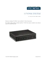
Page 76: ...Figure 5 1 External Controls ...

Page 77: ...r Lift cover carefully to avoid damage to the screen 2 Video Shield Cover To detach Video Shield Cover remove 17 slotted screws designated by arrows in Figure 2 2 3 Logic Assembly Adjustment Access Remove slotted screws designated by arrows in Figure 2 3 Grasp the cover and carefully slide the Logic Assembly out approximately 5 inches 4 Logic Assembly Removal Refer to Figure 2 4 Slide out Logic As...

Page 78: ...U I I Figure 5 2 Video Shield Retaining crews ...

Page 79: ...L1l I L1l Figure 5 3 Rear Cover Retaining Screws ...

Page 80: ...111 I 0 Figure 5 4 Logic Assembly Interconnections ...

Page 81: ... Figure 5 7 invert chassis and remove the three 3 Power Supply Retaining Screws Figure 5 8 Set chassis upright and unplug Power Supply cables Remove Video Power Supply Unplug CRT socket and yoke cables Figure 5 7 Support the CRT and remove four 4 CRT retaining screws on each side of Video Shield Figures 5 10 5 11 Carefully lift the CRT up and out of Video Shield NOTE Observe CRT handling precautio...

Page 82: ...U1 I co f1 f Figure 5 5 Logic Power Supply Shields f 0 ...

Page 83: ...111 I 0 Figure 5 6 Logic Power Supply ...

Page 84: ...111 I o t fIfI If t w IP I t t 1I dIiH it A i i i i e c7aO a C C I I c _ e e Figure 5 7 Video Enclosure ...

Page 85: ...0 s Video Power Supply I Figure 5 8 Chassis Cabling ...

Page 86: ...d detach composite video board and spacers 11 Logic Board Remove black nylon nuts and two 2 4 hex nuts on front edge of board Unplug Keyboard Interface connector and Data Interface connector and carefully lift logic board from base plate 5 12 ...

Page 87: ... operation in conversational mode The F and H position select the full duplex and half duplex conversational mode respectively The following adjustments and controls are accessible upon completion of Step 1 and 2 of the disassembly procedure Refer to Figure 5 11 Vertical Adjustments There is a slight interaction among the vertical frequency height and linearity controls A change in the height of t...

Page 88: ...Figure 5 9 Internal Controls ...

Page 89: ...111 I 111 Reta ini ng Screws Top Figure 5 1 0 CRT Mounting Right Side ...

Page 90: ...VI 0 CRT Retaining Top CRT Re t a i n i ng Screws Bottom e Figure 5 11 CRT Mounting Left Side ...

Page 91: ...nt of the linearity sleeve has been determined make a mark on the sleeve and reinsert the sleeve to this mark when removal of the yoke and linearity sleeve are required If the linearity sleeve is inserted farther than necessary excessive power will be consumed and the horizontal output circuitry could be overstressed 2 Adjust the horizontal width coil L101 for the desired width 3 Insert the linear...

Page 92: ...his control does not have a large effect on focus Centering If the raster is not properly centered it may be repositioned by rotating the ring magnets behind the deflection yoke The ring magnets should not be used to offset the raster from its nominal center position because it would degrade the resolution of the display If the picture is tilted rotate the entire yoke 5 18 ...

Page 93: ...ation to a smaller component may be accomplished in some cases with the use of oscilloscope and multimeter 4 Replace the faulty module or component and retest by running the same operation in the same state the error occurred 5 Record for future reference the symptoms cause and module or component isolation method used Failure Isolation This section will explain briefly the approach to failure iso...

Page 94: ...the If as a Set the contrast control to the middle of its range b Turn the brightness control clockwise until the screen is bright then reduce brightness slowly until the background is barely visible The cursor should be present c Adjust brightness and contrast for desired presentation d If the cursor does not appear check the power supply voltage replace the monitor if necessary 6 If the problem ...

Page 95: ...lear Memory 1 2 Clear Memory Power Up 1 Cursor Control 1 2 EDIT Control Option 1 2 Parity Error 1 Receive Data 1 Transmit Data 1 2 Video Character No Cursor 1 No Character Cursor 1 No Character No Cursor 3 2 1 Data N o Sync 2 1 Data Wave 1 2 I Randomly Generated Wrong Characters 1 2 I Check word structure speqification and baud rate Insure good connection of cable from keyboard to logic board 5 21...

Page 96: ...OLTAGE BEFORE ATTEMPTING TO REMOVE DISPLAY ASSEMBLY Display Troubleshooting Guide 1 Screen is dark 2 Loss of video 3 Power consumption is too high 4 Low voltage bus incorrect for units with a low voltage supply Check A bus 0106 OlOS CR lOS 0101 Check horizontal drive wavefore check proper placement of horizontal linearity sleeve 0105 0106 0202 0203 01 Note Low voltage supply will indicate low or 0...

Page 97: ...11 n l HJ H V Q101 8 VI CATHODE CRIOI ANODE 2 5V p p 20V p p 3V p p l t Vl 1 l V V V Q103 8 Q104 8 Q104 C 4 5V p p 1 2V P P 45V P P ILf n H 1 H H Q105 8 Q105 C Q106 C 3V P P 30V P P 170V P P Figure 5 12 Voltage Waveforms for Display 5 21 ...

Page 98: ...h one exception D C logic level 5 Volts is obtained from a separate POWERTEC power supply For maintenance and trouble shooting refer to Table 5 3 for identi fication of connectors and terminals external to the main logic board and normal input output signals Connector Jl is used for Data Signal interface connection to the main logic board Connectors J2 and J3 are used for the same purpose 5 24 ...

Page 99: ...d Line Signal 19 Secondary Request to Send Monitor I O J4 1 Brightness 2 Brightness 3 Brightness 4 Contrast 5 Chassis Ground 6 Video and Vertical Ground 7 Horizontal Ground 8 Horizontal Drive 9 Vertical Drive Logic Board Power J5 1 AC Feed 32 volts rms 2 AC Feed 3 Equipment Ground 4 Speaker 5 Speaker 6 D C Feed 5 volts Keyboard I O J6 1 CTRL 2 RESET 3 4 BIT 8 5 BIT 6 6 BIT 4 7 BIT 2 8 BIT 1 9 BIT ...

Page 100: ...LOGIC BOARD TERMINAL IDENTIFICATION CHART Continued Connector Symbol Pins 15 STROBE L 16 STROBE 0 17 20V POWER 18 GROUND 19 GROUND 20 POWER 5 volts 21 POWER 22 PROTECT MODE 23 CONVERSATIONAL MODE 24 PROGRAM MODE 5 26 ...

Page 101: ...3 C4 4 C4 S C4 6 B4 3 B4 4 B4 S B4 6 IND 7 F6 S F6 6 F6 11 F6 3 H6 S H6 6 H6 11 H6 3 CNTR lS C19 S C19 6 C19 11 C19 3 B19 S B19 6 B19 11 B19 3 CMA 9 B2S S B2S 6 B2S 11 B2S 3 B26 S B26 6 B26 11 B26 3 OTSB 14 C2 9 C2 S C2 12 C2 2 B2 9 B2 S B2 12 B2 2 Bus Driven COND 17 A2S 4 A2S 3 A2S 2 A2S 1 A2S 15 A25 14 A25 13 A2S912 WDR 14 K23 4 K24 5 K23 12 K23 13 K19 4 K19 5 K19 12 K19 13 ARTO 20 Dl 26 Dl 27 D...

Page 102: ...20 1 C20 10 C20 9 B20 1S B20 1 B20 10 B20 9 COMPAR 18 F23 9 F23 11 F23 14 F23 1 E19 9 E19 11 E19 14 F18 10 MAR 10 C4 14 C4 13 C4 12 C4 11 B4 14 B4 1 13 B4 12 B4 11 MACC 12 H23 13 H23 10 H23 6 H23 3 F19 13 E18 9 F17 4 MACR 12 H23 13 H23 10 H23 6 H23 3 F19 13 Table 5 4 Tri State Bus Signal Locations Continued 5 28 ...

Page 103: ...eyboard assembly for obvious faults Either repair or replace keyboard assembly Keyboard output levels are compatible with TTL circuits with logic I greater than 2 6V at 10 ma and logic a less than 0 4V The outputs are bounce free so that only one signal will be generated for each key depression Two key rollover interlocking is provided for all encoded keys If a key is depressed before a previous o...

Page 104: ...5 30 J l o I I d I U H o I d m i tTl o I t I d E ...

Page 105: ...he replacement of a component on any printed circuit board requires care to prevent damage to circuit board etch Clipping a component from the circuit board rather than unsoldering is the preferred method Excessive heat from a soldering iron may result in damage to the component being replaced The use of a soldering iron with a small copper alligator clip as a heat sink and a delay between the sol...

Page 106: ...ons in this manual are cancelled when the Planned Maintenance System PMS is implemented for this equipment aboard your ship or station Scheduled Maintenancel The scheduled maintenance activity involves a weekly task and a monthly task The weekly task requires external cleaning only The monthly task requires a straight forward test and if necessary simple adjustment In the event a malfunction does ...

Page 107: ...ll adjusted display and assurance of satisfactory operation Procedure Item 1 Plug in T 5l0l to 117 volt AC 60 hertz source 2 Turn on POWER switch on T 5l0l and allow approximately 30 seconds for warm up SHIFT LOCK light on keyboard should be on 3 Cursor should appear Check operation of BRIGHTNESS and CONTRAST controls a Adjust BRICHTNESS control until raster just disappears b Type A and adjust CON...

Page 108: ...splay 1 1 1 1 8 Using Cursor controls position cursor on le t ter G obtained in Step 4 Press CHAR INSERT and to display Press CHAR DELETE to display GABCDFF HIJK MNO Press the LINE INSERT to di Play I _ 1 Position cursor on letter V Press LINE ERASE to display Press LINE DELETE to erase entire line Position cursor on letter H Press PAGE ERASE to erase all characters on display except those preceed...

Page 109: ...DIT PROG MODE CONV MODE PROT MODE SHIFT LOCK WRITE PROT Depress while simultaneously depressing SHIFT key 10 Short between pins 2 and 3 of data interface connector Set FBH switch to F press PROG MODE and type ESC C CTRL G RUB ESC A M ESC ESC f 2 ESC f RETURN B C NEW LINE D ESC E E ESC Q F ESC N ESC HOME RUB RUB PROG MODE 6 4 ...

Page 110: ...Item CONV MODE SEND LINE The display obtained is shown in Figure 6 1 To reset the program press CONV MODE PAGE ERASE PAGE EDIT ESC Position cursor at end of program Then press CONV MODE SEND LINE 6 5 ...

Page 111: ... program displayed r _ r r Protected I i t Blinking i Ii Protected Figure 6 1 Program Display 6 6 o r r J J ADM I Mode PAGE EDIT ...

Page 112: ...ilters to chassis ground before touching AC connections Unplug the T 5l0l from the AC power and discharge the 2nd anode lead to chassis ground before touching the red high voltage lead to the CRT 2nd anode or the 2nd anode itself or the flyback transformer attached to the read lead Discharging circuits to chassis ground requires the use of an insulated test lead with a pointed tip on at least one ...

Page 113: ...SECTION VII T 5101 SCHEMATIC DRAWINGS AND DIAGRAMS 7 1 ...

Page 114: ...NOTE Figures 7 1 through 7 21 provide Logic Board schematics for the 7 configuration board Figures 7 22 through 7 44 provide Logic Board schematics for the 13 configuration board 7 2 ...

Page 115: ...11 0 BY r i 4 Y PEO i REn AC F covNrS UNE5 CF CHARACTERS 1 I T4 5 U A BI 3 __ __7 E 7 1 6 B NARY Ie Li el FA T Cat ITER K 7 CLEAR JIB 13 CLel 2 LLI Ao 80 CO 2 n I r II 12 1 ChiC t____ __ ____ __________ IK 7408 I J I M III He o C I r2 C RQ CVE SOR IT 74 L _ l Figure 7 1 I l l5 c R 2 C L7 Z _ A 74 74 Ci C 2 2S 5 740D 4 6 5 7 02 ...

Page 116: ...Z A L_ _ ______ E 1 f i T A p 9 r 9 MACRI 8 I L ____________ O B fE L RAM If RB 6 7 IfI03 7 r 9 C Z 1 5 A I L ________ _1 RAM l R 7 II r KI71 5 I 74161 J 19 12 13 14 A 20 MACR2 1 3 f 8 74 57 II A 2 1 D I T t MACC7 6 5Ft S A tWANG 5 2 A MAce5 2 B stL ST 2 A 3 5 L 1IE Z _ VV IV r I S rU RAM Ift G 7 6 r ___ _____________ _LS_f_L__ 5T 9 64 7 i L 32 7 s 6 1M lPR Z 3 4 g MtlfT BE vAl ECUJ TO Ie R5 N rif...

Page 117: ...5 S ItI 1 o J 3 r L24 L23 L22 r1 9 10 t i 2 IZ 12 8 L 3 _2 r MZ I MZ3 I McZ 9 l r 70 70 0 I 3 0 18e eL ft 8e Z e TS 8k C t 12 y lM T T 1 5 JL 1 5 If 9 9 J4 t Figure 7 3 f 5 5 1 u j I S I 1 3 l il 3 3 1 3 I t L21 L O L 9 9 10 9 9 10 2 IZ ie iRk hl MZI Mea If 9 9 o 0 0 8 8 1Il 1 18k IZJ r 7 9 1 12 t 1 9 09k 2L 1 r ff 1 9 5 4 5 If 9 9 I 1 J II REFI ESh M FM RV II ...

Page 118: ...vfB S 0 2 ar I ZZi f 13 5 MB4 r Lie 2 IO fR 74 75 5 BZ 14 Z 1 1B I I I L CflC 0 tJ lb Z_ nll eLK JL7 1 11 RiG ppcz _B IZ a Pc I 74 Z 1 Lh C Q1 j Ii 7474 13 Figure 7 4 25 32 9v 9t 80 5R 3 i JUTI SEB KlCl 6 b1 A Z 4 t rZ Wei 5 7 f IN3 OUT3 7 RE 3 5 IN OUT4 13 REC 5 5 N 3 r b L I 4 I 2 5R3 If 7 SRZ 5 13 L s R J 3 C C L II 3 4 14M 1 eEG STER CLK ...

Page 119: ... I i I 121 I B 1 93C8 C Ch P A TER SEA ERATOR 20 CIIC 8 elfC 4 eNC Z CNef ______________ _ 8 ______ 3 fORI BLANC m LCo2 5 74 10 13 iIof l3 if NII ftiM IA lAd 7 V t N Rev Iv e 17 A S R 4 ReM A i C I I Z 2 4 INI 81r Ii L 1llAf1 M i i INK 7 9 JAVJul J P iP3 C 1 1I 8 4j4 5 C CCLK CK T CLC 25 Figure 5 0 __ 3 Cb DPC4 7474 ...

Page 120: ...93 f JE vTR 74 25 T581 TS132 7585 T587 75B8 IAlOltENi s c7i Z8 z FlO CLCI 4 I 7426 2 1 3 LCI 2 CLC4 4 q5 3 JJ2 03 D IDS 15 J 1 XIv1 T 2lvO 7 __ _________ 3 Figure 7 6 Y BOAfU J6 24 I P cA r bJ ORIY f I EY60AgD J IZ I IJI tU8 I BI CLa 12 7 10 7 7 7 y5 TR E w IA t 1 E A V I AlOTE I U R 1 1 I CL 51 19 5f I 71 9 I I L 5F 5 RAf _ CI IC 7 7 I ...

Page 121: ...5 14 2 ART 13 ART T 5 7 1 I 7 8 T57 3 2 T5TC y T57 L _ _ _ 3 4T57E i C 3 _ C I TS v TS72 j1l 4 3 1 CMOXX IZ I 740Z CMO lr 1 J V CJ1t Y 4 fIJZ 7 4 r C iLL 0 L 4 74175 5 i 4t9 77 1 CALL OEL 3 I TN L 4 3 0 k7A EL T5 7 4 _ _ _ _ _ _ _ _ _ _ N Z MAC CON 11 _ 11130 16 0 T58 COl O ____ i 8Z ZMPA e J 1 1 fR Cl 10B Figure 7 7 CMP X _____ 1 1 EZ3 115 II 3 01 f Ch16 ___ J IZ 2 3 2 C Mf JMI F 4 1 0 7411 1 1 r...

Page 122: ...16 1 Z 3 OP 8 C 9308 07 Ch APACTER G AJERATOR 9 CI lN8 2 4 ll _ eM IA 4 poM 1113 R 7 t1IJ Z ROM A I RI y III e RM I RCNIN6 _ _ R_ 5 ROM N4 B 3 7430 RCN 1 2 20 ____________ ROM N 5 9 b KrJMIN4 U MI 2 RIOM A I 74 6 e 8 T n C T eE G All 7 t7 YIDEC 3 T 5 V J4 f 0 2ro 500 IIfcJ u oe B V I EO 74 01 T1 1I I ra o e r YE a t II 5AI 5tJ PF j ii 3 KOMIN 8 2 8 AlL LEAI S 10 K4 a 74 06 C CCLK L C 5 CLC 26 7 j ...

Page 123: ... 16 9 10 5 BLINK eLK 4 74IZ5 T581 T5B2 583 584 741Z5 75B5 T5B T5B7 588 JNDI 2N03 INDiCENi CflC8 c LClo CLC4 CL C I 5 Z 4 FlO I 7 12 7 4 j T 7 3 1 N RI A 5 7N04 03 w Y oh Z c oEO IND5 15 M xMIT 14 IN 6 ___ v f S AI 7 f 51 5 1 Yf 3 INO 7 __ YBOARJ JG 24 Ad ICAr_ O I If IX k E r60AE D Jfo IZ 12 IMJ B J 7 82 CLC2 c 9 I e C La ____ I Figure 7 6 1 61 LCB 1 81 Lei 10 II 1I JTE 1I o C 41 1 5 ON LC 5t7 9 3...

Page 124: ... CNO OJ 74 WHRW RJ4IF 7 6 y CA Tif Fc6 PPCf 3 L3 PCZ b 91 B 7 f 3 pe 741f 7 1 i Z CL t 7 6 A HY C vT rc4 T 17A 1 I I 7 04 5 F _ T5 7A ___ d t 2 C Z F 8 C ORW ENPL ARTF HIP 3 ARTF ChfoXX3 __ __ eM7 E ER 743 Figure 7 7 TS7 TS7E 7 CALL DEL ____ 5 j4P _ 4 CALL DEL 74175 3Q C PTNPE L 3 3 RT VDEL EZ3 1 3 l 2P cQ 5 _ 4 C 14 Mf JMPF 4 10 ICl JMPF TS7c __ Z j 1 9 7F II JM7 j CU 1 i REf ETL Ct J ____ ___ __...

Page 125: ...4 83 82 81 PA6E 0 0 3 17 7 1t5 b 11 5 2t 4 1 CM 910 l OEI Ztiii O OEI CAM II E O t eM 111 L Oli2 j b OPT f PA6E I 4 7 MO TOROL 9 MCI I1 65 15 L Figure Kt OP7 I PJlf6E 2 8 11 OPTIOA I Z f edM 7 8 AID Af A8 1 7 A A5 Af Ai AZ A Chili I Z OE eMil 1 l OS Z K Z OPT 4N PA6E 3 I T s8 3 CU C M7 T 81_ 11 CZ6 7 5 8 _ 4 2 T fM_ rS84_ TS83 I 2 6 Me T 5 JZ dS CMI TJ81_ f ZS RTAlNL 12 I I lKt 6 z Nt6 M6 9 loye6 ...

Page 126: ...3 PI3 5 CMPU4 CA I B S C H I X5 PIS 4117 A CM6 2 9 cMDllX CM6 i P 9 744Z DI P I 113 LJ O I II CMOl2X II 13 CMDI3X 13 14 14 IS CMOl5Y IS C 11036X J 6 CMDI6Y 16 I 74154 74154 I 17 CMDI7X 17 I tJFlG PECtJJ f Id il PEL i f kOMMAND 1 DECODE l tJ i tb H j l j I J II tb tti tti tti 01 6 J CMD 4 X Nt 13 12 II 14 13 12 II CMDXXZ 9 14 1 ILJ ZLJ 30 4LJ H 74173 I INZ 74173 73 70 7 7 cLI f C4 O lT 84 rsa U4R o...

Page 127: ...I 1 81 Jel 13 AZ 4 15 8Z A3 83 A B O lT 7485 74211 C lfPtlXC2 7442 I yACC NACR CtJN o T iM ClRCtlI711 CPC NACCI epez MACC2 CPC4 AMCC3 cl Cg MA ce 4 J AZ CtlLStItfl AJ L N i CO A IUCR I ItIACRD I I lZz CPCI6 MAces CPC32 MACCr CPC6 f NAce7 C I C Be Figure 7 10 CMO BX CMOXK6 TS7A ChfOXXI ChlOx rz c UX3 rs CMOxr TS7A CMOXX CM0I 3X CMDXXS 741t1 13 I Z B 9 rS7c II 3 AlACCSET IZ k 3 5 74 Z 3 N NACC PC 4 ...

Page 128: ...C 6 3QA r J 4f 4a PRC 4 EZc_ 1 cM3 NBG II 7f85___ 0313 1 14 1 1 MAC IN S 15 3 MA CC 5 I II ii I 14 t to J r 12 V PN 3a __ 1 2 1JP Q I PRC 3 7 zG l 15 7 5141 _ S 2GI CPRC2 3 8 ZTSB4 _ I e 74tJ4 2 T 7 1 8 3 5 r I Z7f8 If c j II A Zb Zit 3 3 311 1123 I __ M A C N 4 ___ f_q j c 73 7 MACC r Pf Po f 4 J MACIN3 If MACC3 n Cf Co J 7 1193 r ___ M A_ C IN 2 ____ _l 2 MACC 2 BI 4 _M_ A __ C_ AI ________ 15 j...

Page 129: ...I6X __ 1 __ 7R CN 017 2 4 I 7UI T 57C 5 12 13 H H3 l t 15 123 74 Z P C B R 7 4Z eM7 5 CM6 IZ 4 eMS I 26 C M4 9 17S CtJC CU 5 IZ E2S eMI 4 1 3 7S 9 U C fl I 6H 3 I T5 1 z 3 T 58 INPVT TSS MAR 5 TJB zN IJ r5B CTR 7 9 T5 RlJe T 5I3 t y Tf J RCV Tf8 LIT TSI3 CPC n D c R TSI3 LRC II T 5 B SOtIRU D o oe l Figure 7 12 If LIT 7 3 Z LIT 14 IS LIT 5 I 7 LIT T 5B4 1 7SI3_ 3 z T 582 I 5 T5S1 1 7 5 754 IT ...

Page 130: ...8 R DR I 1 RUO PIiTII REGIJ7FR II CAf 9 CI p X6 8 TS 7L CMLJ IX b CMLJX 7 5 7 12 2 TS8B T 588 lT587 TSJ9 7 I TSS 73 36 T585 74 8 741 8 IT SM TSB4 Ii 1383 T SSZ 7581 II TfS HER I c IIfD C MLJ XX5 r T 57C CMOI fl x _fC _ LMOXX4 5 L J Figure 7 13 J fNI 3 7 5 3 II lD 30 13 WRIT OT 6 0 PWOB 1 3 IS Ie Ie PW07 kCI9 1 5 7 PWO 6 4 Z PW05 74175 3 9 eLI 13 40 15 PUll 4 J 1 234 I IlJ 12 3P 30 PW03 30 II 5 7 o...

Page 131: ... BlAI 9 ey 748b PRes CPRC4 CPRC3 CPRCZ CPRel T5B CPC CN1 Y z _ CM XX5 1 CIS 1 3 YBIAI Z 74 6Z T 57C TS13 a rS87 TSB TS8S TSlJ4 TSl33 T5BZ 15 3 I 2 TS88 Decse CM 5X CIVO l rS71 CM A 7 TS7 Figure 7 14 74 25 TSBB TSB7 TSB TSB5 T583 TSBZ TSBI J ...

Page 132: ...TL 13 K 74_ 51BI 5 Tt3 2 STB3 57B4 5Tt3 5 FI cO OOT 57B0 5713 7 TRR ST81 5TfjZ 3 btl 5TB3 Z I 7415 _ TB4 2 1 yS 5TBS 15 PI ST86r I P5 Cf 7 5T87I n A 5T 8I IZ D7 VII S TB COtVO 5 CMZ C ehf 3 seCLR 0 CM A 5r 5 G CMf V t C chilJXYi 7 f7 lJ 2 CIJ10tNX 0 cIYfOX EY 31 T f17 vPUT 8 REI ClrS i RC56TL 2 CHC 9 581 0 8 513z i SCROLL FIFO IN TSB3 T 5B4 I V V 20 T5B5 0 V rZO 7386 0 5CI OLL OPIV CPIIIPL 7 587 0...

Page 133: ...CMO XCIX 7 1 03 14 K Y TR08E I 815 4 13 CM vXCFJ X MDJXC Y1 D lXCZ MDv XC3X MIN xC4 CM Jxa 1 CMP J J3x IZ cM DXX7 13 Fap 7432 DC 5 zz Jr e n r o J 7 N 3 7 LJ S 8 7A 1Z TJ7 ___ _________ ________________ J 1 1 1 5 2PTIO u I II 57POLJE ClRCUlill 7 I CIIfO 5X _ 3 r_ z CIS I C M D X4 1I Z 9 AlS _ 2 I T 57 c fA Q 7 Z3 I 1 TIME on I CAh J xcZ z II JCI 74 _ Ch1 DXX7 OAf TINE I 74 Figure 7 16 13 71 L III ...

Page 134: ... BB 3 13 LIT 7 T5 37 14 S MAce6 7 6 Ie LIT6 7 I MAces II 9 II 74157 10 LIT5 c ISEL I 15 T5 35 __ 9_ MACC4 14 4A Ii IT4 13 48 4Y NACC3 z Fn 4 34 LIT3 3Y A fACCZ 5 2 4 7 eY LITZ 2 6 hMCCI II IA 9 LITI 10 g Y T 584 43 l3 AZ i J J 1 82 12 AI T582 II 81 10 AI I lftft 15 5 L 51 581 9 M eMI 74I1IJQJ 7 1164 Figure 7 17 eMP Z5X _ 9 4 eMP 35X 1_0 B CMZ 1 3 COM C4N Elq 7 135 C MPAR 23 74B5 CdMIHR CIlM PARI5t...

Page 135: ...1 AZO If 15 20 21 18 EJ 5TROB I 5 1 5 GAJD I _ GAIL 2 RESeT IUOT IUOB 1 0 3 CMO 1 IY __ 2 II C fO YX7 II r CL C4 8 O le 1f16H I 13 23 14 17 7 64 9 J 4 5NIFT REG 3 4 5I T 1 10 31 aTMOP 1101013 COAlY MOPE BREAK 20V 5 10 II LAST VIPEO CLC2 etc I 9 1 141 74 IA IC GAl Z Figure 7 18 8 PROT lftJ CPC8tJ 14 CPC4 _____ uli C PCe _ r ePCB L e CLC Z3 3 IZ 3 7 9 1 s Cf CZ cNC JRIJ E z II OIC EIV 1 JIZ 7IJr ir ...

Page 136: ... MTO 1T f I 7584 28 I T583 27 I 7 58 Z I T 58 I 26 CMOl33 9 8 23 111 F l 7 32 19RT c I 5V ct 40 g 3 eJI 39 2 COO 13 5Tt5P T EJZ 38 781 II RPE 37 3f 11 6 4 If 15 R B ARTflLl II RR 7 rRE5ETL 21 14 RR Pi CLK 17 7 PR5 2 I RR4 fRTI I 4 IB RR3 IIIlTSEt I 03 14 128 t9RT IZ kRZ LIdO 1301 4 18 I P I AR7F 5 F9 743Z 10 RDIf 7474 Figure 7 19 4 12 7 9 24 TRE 1 22 Th ee 25 1 0 I f5V 3 z 2V 3 1 5 RR8 0 RR7 7 RRt...

Page 137: ... e II L 2 q 14 13 IZ t t cl I J 1 0 9 FZ 0 4 3 O 300 600 lZOO 12 P4 P m 4z liz Cr Dr F t 1 iE r 7 61 c 7 JIP 6 N LY CA TR r I_ Z lfF F 1 7iJ 4 8 CD P 31Z l l J 0 PrcLK a 2 34 7 14 PRINTER PtJRT E L EC T Figure 7 20 124 J I I I 7 9 00 I 011 6 4aoO Z 101 S Z I Jo 3 00 4 IZOO 4 I I o 3 ao S o I 02 300 6 110 o I ISO 7 00 o 0 I O 8 9 ...

Page 138: ... A 6 RTS J 1 RTS z C 6 CMD 12X 740Z T57 1311 el lDxx2 8 jlllA CMO 12 12 74 113 5v 3900 7408 XMTDAT A NOTES I IN fTIUt JJ4IPER TOIA I BIT REQ TO SE uL Aj T L Rev LINe 5 G PET CF J F 9 i S t lS 14 7 1 2 Z rYPE MObEN A lALF DrlPLEK MODE Z INST 1LL J IIIPER71 N IBITRT f CA Y 7 L IS D t B 3 IA ST 1LL t MPEF FOR KEYBOARD BRE ge S 6N f L Figure 7 21 T57E 5 BIO I 8 RT5fJ ff 3 CTSIJ JI 110 A8S 4 _ l13 lOOK...

Page 139: ...r 3 L3 L 1 4 14 4 I j I rc T E 6 i L OD r E R IL J Yy LJE 81 8 AR T f 1 8ER c CAS r _ N 1 5 7 7 6 8 NARY 1 7 C cp TEA 8 t 1 J 9 7404 J o 8 I JlNE II 12 1 eKe 13 It 7dOB I 1 1 tD I J 5 10M c c c Cili lOI tI Figure 7 22 AI 6 5 I CNARACTER LI U1 TEIf I 1 11 sy 74 YlCEO ZRETRAC II CClI A S UNES c CNARAC TERS I r 1 1 I 5 JIb 6 I ...

Page 140: ...Z A D r 8 SEL 5 A G I 2 I 3 B 13 1 v 10 2 3 I 7 4 P55 6 A IS A 5 Sf TJ J f v Z 3 4 16 f S5 1 1A EC _ I _ I 1 K ZZ r5 L __ i 12 I J I UM 3 SY 74 57 Z I I i A 0 TIQ 9 MAC 3 cpc MAce 10 fEL 5 A 7 cPC Z 1 Y A C _ S ___ L___ AM k S D41i1 MEMORY Jif 5S 7400 Figure 7 23 ...

Page 141: ...10 9 10 9b 7zT I 1 r L I 1 l Ll t i 1 m J i t if 12 2 IZ 2 I 3 Ii H 4 H t I H H I I I iH 4 I I u i 1f I 1 Ii i j h S 1 3 1 RJ i I LfjI LI Il j I I I ji31 13 1 I i L U W I I I I i I II I I I I All _ I H I I i 1 II I 71 J r ZI U 9LJM 2 101119 Jt _ 1 i MIS I _ i 9j 1 7 m I L 0 0 0 L z 0 II 12 8 2 Zl I I I I I I 9 1 9 1 1 Li1 8 I 7 Figut f 7 2 ...

Page 142: ...A 4 a TZI 5i 7 12 It MB 7 JP MIZ 30 PRt 7 4 f RFCZ r j 3 ollr31 7___ Y G Q 5 c 7 WB G 7417 _ 0 6 1 t RE 3 f _ _ _________________________________ 5 j A _ OVT4 1 13 __ 5 R5 L5 RU 4 G B S Wt 4 ____ ____ _ _ cf I ______ ___ _ L___ LA700 I Il C 1 07r M r L J J Li RE6 CIL t J i ________ 1 1 ______ _ Ch C 1 L Il __I Figure 7 26 ilJ w 1 4 LI 1 5e3 ...

Page 143: ...2 Al8 _ 8 J N 7 SR7 R I A 6 5R PtJ 1 5 ROM IllS f i A 1 1h Rcrr IAl3 5R4 I B 9 II IZ 1 0 18 16 IS 2 R If NS 4 RIJMIN7 __ _ 3 RDMIAl4 POM 11 3 OM IJ Z ROM b 1 4 7 30 ...

Page 144: ... _________ 3 P INO 3 ________ _____ Z j 2 B _1K K r Figure 7 28 IL __ 4 S 74 51 F7 6 1 PO ______4_ 1 74 18 x 3 I O 7______ _________________ j Dr L 8CJAf J J6 24 I h lfl tC IiI rbJi O IYE t t BeARD t 12 Z lj 8 J 3P iC I a C LC I BI 8 8 ICtI 12 II 12 I 7 I dJl 0 I 3 7474 2 II _ iC ...

Page 145: ... I W W Jh1PF ____________ Figure 7 29 t 7 7 12 Z f t i I J I I I I I I 5 i I 7 6 tI 9RY C TR 5 F 4 3 e ...

Page 146: ..._yfA 7 h1A cMA S LMA I fA 3 0 r c v c o 21 L I 8LE EI 0 2 JZ 5 I t 11 0 c 1 t 4 E I 4 7 1AIO 1 II 0rtlf It eM 11 2 ZZ tEl _1________t____i R EL _ 2 O E 2 e II Yll T i r L 4 MClY 65 tJL PTI lNA A J2 8 tJM Figure 7 30 74125 l ...

Page 147: ...z L d eMS 2 1 c 1 6 2 I I 0 t 4 X i sx rz_ l i x X t S A 4 II l 74 73 L C4 5 O 3 i t l I 3 6 4 til I Figure 7 31 II I1CXX 12 Z fL A 1Z 3 C C f1 1 13 B 7 t 3 15 A 0 tJ 1_5__ 1Y1 J X 6 i a 3 4Q 41 5 c I I I I l i j til til J lot ...

Page 148: ...C L _ 3 _____ c C _ _ j i i YZ __ 4 ___ Figure 7 32 _ _ I TS 7A fL P3x L 3 C _ II R9 c OXXs 741 a 74SI 3 ...

Page 149: ... J I W J 2 _ _ fAC R C I B l A lZo Fiqure 7 33 l i 3 Az 3 20 7417S z of I _ _ _ f ...

Page 150: ... 26 4 Z 14 IS 74175 9 C I C 5 7 2 II E 5 I J 3 z N 13 74175 15 9 u ail I 6 3 T58 i T 8 INPI T T58 MIIR T f8 zNJ r g CTR _ T5 J ROe T51 3 6Y 2 T 3 f Cv J 4 T58 LIT r 5 T513 cPC 5 T5B Cf R 7 T58 iRe 7 q Figure 7 34 117J8 5CJURt t PEco oel LIT 7 LIT 6 586 LIT 5 85 L I T 4 LIT 3 ilT 2 LIT I 7 Z5 754 T ...

Page 151: ..._________ 12 P R DZ _ I I__ 13 12 2Q t 04 r s B 2 ______ 4 TS 7D 7 CtJ 74173 PRO I 4 I q 3 T n I r UJ8Z RWI 9 MiT I C2 LTT581 I INZ L 13 1f4 15 at M O a I 2 II TfL3 I FER I Figure 7 35 NI 3 7 5 1111 _ 3 D 30 10 B WRIT PROT 7 IJZ e W08 IS 1 3 T 5138 14 Ie 111 TSI9 7 PlY 7 KI9 II 5 7 TJBt t oW Z TS135 4_ owes 7 7 3 9 c u I cu 13 1r 5 ________ TSB4 I j 4 _ I e 2304 1383 _1 24 30 138Z 11 5 1 C O 7417 ...

Page 152: ...2 l5 6 LRCS7 R 7 n 5 II 7RZS7 T5B7 l I T58 ij C LRCS RC 56 4 lJ5 3 rsa JT5 1 15 IS LRCSS L K SS 5 8 13 7585 14 7FCS5 9 I 583 IT 5BZ 5 6 2 52 4 E5 t_4 l ZD 1 3 4 j F5 Q J 7 581 9 B 13 1 1 5 Z _ 2 5 LRC51 W 31 lJ 14 9 I J L C 5 d CL I CMDI5X l 8 CNOUl 1 0 _8 __ T 7 1 7427 I I 7 O 4 4 r 5 s J RC J iYijj 5X C MLJxx7 T5 7 74 27 Figure 7 36 ...

Page 153: ...3 4 RESET I STBI STat 4 btl 5T8Z 3 5T L DI 7415 5TR 4 z P 3 1 5 5TtJ5 IS 5T86I I PS ell TS 2 STiller 3 I W 5T88 1 12 D7 ST8 CIWP E CIWZ 1 c s CMI 8 5CCt R l CMcZl A Tr ST133 0 CHOv C6 f5 ZhiOxn 5TB4 7J71 2 CIrlOtMX V IrfO lKcZl 0 5T8 5 V n co OOT Z wl tlT Q 0 4 RErcu s 8 I 57 86 Rcrat 0 I O C 9 I IS 81 V 7 5132 V 5CROt L FIFO IN STe 7 T583 0 T 584 20 T 5BS V V tZO T 5B6 V 5CROLL OPIV CPMPL 5T 3R T...

Page 154: ...7 MOJXC Z CMP 3X 3 cl 7 32 I l T 7E e eLC 1 9 5V 191 I So i I 1 5 I li J GO 9 8 0 F J 7 ee t5V NV oc 39K 3 ___ pc r E UT ___________ _____ 4 2 COAlD CB I _I o I C lfor 5X C MOXK4 _ 1 I Z 7 I l J is Jl6Z 8 c 9 AIS 2 IA a z 7 Z3 8 Il I 7 11 CMO C ZX 13 II CI4 7 6 2 r z Figure 7 38 T57 10 I I 6 PIA I P PJJV I I_A k J IGO j 5 4 t RE 17L ...

Page 155: ...MACC3 _ J fBZ LiT3 5 r 581 MACCZ_ LITZ hlACC 1_ 1 LITI 10 CMI P24 M I_J r 4 II Cffli Figure 7 39 clt1e 1 If I r 7 18 I e I 9 I T BB 7J 1 3 C 4 I 14 UBS I T 513 7 C tI4PAI I It 7 i n 1 L I 10 74 57 9 c fEt 7SI35 __ 9_ e JJ r 71 r 1 DII Th IE A3 c23 4A ifY i 43 7 504 7485 FZZ 4 AZ MI A f JI 31 7 JtJJ _ L 82 12 7 A 2 4 2 rJ1J2 81 I AI I 1tI1 1 1 fBI M I J 51 _ III I fAl 1 57 j I i I I AlA ...

Page 156: ..._i __ 5 _C_RtJL N1 IN _ t _4 l PRe 1317 _ _ PR Ii PRo7UTEf 01M r vUIJZ NIIIO 5 C oYX __ T5 70 2 aI BIJ C M IZI II f Ii PROTIlfOf E CMZ CMI CM 4 6 15 L t 1 JSt I t EYf T i BE f 7JZ C M0 Y 7 ____ ti J 741 Z O 1 GA O c ePe5t T 4 Iki 7 Z i lO B r v oC CLC4 CL C 2 etC T 64 J 4 5NIII REG 4 5 10 1 I 74 Co PC 8 tJ CPL4 A G rI __ J CAB L 7 ALC Z3 c IA OIC II 7 1 A20 474 4 l5lnn lA Ole GAl 2 C c Z 5 _ l i G...

Page 157: ...Io U OlD tI Z4 TR dJ TliRE AM TOltTIl 5V 7474 3 5 zT f j 8 Z 7 f1J 7 TJtJ6 Z 7585 I 758 oJ I TS8 3 I 7 58 Z I TJ8 __ 1 8 3 fI PI 32 T eLi ___ 4_ 0 t II I T5lL 1 rRE5E TL ZI PL CL K __ 1 7 j Figure 7 41 14 12 lRT 4 12 7 1 Z4 TREI Zz THee 1 Z5 T OI I f5V 3 z I V 3 RPE 5 RR8 l R7 7 RR a RR5 9 RR4 1 RR3 II RRc IZ RR 1 y 5 t 4 W _ 11 if 5 3 D8 9 6 1 _ _ _ 2 eM 1 c 7 1151 tfl CMz e1 CNilJ C 3 X MI ART 7...

Page 158: ...00 I 3 9 ztJo IS IZ II 400 14 S y J eCt i L I 3 12 IV 12 4 I b I li 7 9tot o I 6 4BCC e 0 II S Z4ao 3 r c 4 2150 4 I I 0 3 cO S O I 02 3 0 0 I 50 7 000 0 I O 4 6 B Mile Z4 71 01 5 9 I J I I I 0 1 I 3 JI IS 7 1 61 Z4 q rl fm Lf D 11 c P II 14 N 3 z L1 1 _____ 1 _ I f l Figure 7 42 ...

Page 159: ... I 5 EI T N 5 0loJ 2 3 CMD I eMf 2X C D 2 RT5 E 4 eMO I Tilt 5 Z 3 740 TJ7 1311 1 13 0 12 elf I2 fCH J8 7 411103 G 6__________ 9yAII 8 ___ ID MOT 2 1h 148S 8 _C_C____ I lfAiiA 4 8 I 8 CT5 r II 1 r r I 1 70PF L 1488 S l rSs1 L J CF 2 I 1 13 3 74 2 4 All t Ie r L 148 I To C L q seA 6 A f JI c 4 SCF Uk 1488 20 t C_ D_____ 3 Figure 7 43 9 7 Z 2 0 1 71 ZI 4 C7 S0 e7se JI l 0 t i Z Il ...

Page 160: ... J 1 Ii CO FDX U JDE j C 7N1 CJ J l PZ c Uj iD KEY I J6o r _ _ oIC t I r Yi P L ______J IJL1LL Figure 7 44 TRJ 7TATE BU r J iZ tricR fZC c lD tr 19 A1 11 2 7 C Jt t 2L 70 U J z ...

Page 161: ...0K EACH y 2 15 YF2 14 2 t t II l YB 2 8 19 2 7 1 62 4 I Loe FI Loe E EI Loe o 01 I 6 I U I Figure 7 45 RI ICK C 1 OIJ L 1 6 a t 74123 5 R3 CK R2 10K _____ 1__ __ __ _ Keyboard Schematic _ _ _ _ 4 1 d ______ 2 I A10b AI9 AI20 6 t l7a A19r AI20 ______ 27 A14f A2Zb _ _ _____ RP T E _A TRIGGER ...

Page 162: ... J I U1 o TAIGoG R 02a _ _0_____ _ _x_2__ _________ J Bl 1 I p r EN B c M 1_____ 811 8 q Bl 2 ______ Bli BI 1 1 20 IJ I I All _ A II 2 2 eZI ro2 1 Figure 7 46 Keyboard Schematic continued ...

Page 163: ... NT P A O R N OM E N C 7 T U RE ITEM O IDENT NO OR DESCRIPTION OES NO REQ PARTS LIST E I UNLESS OTtiERWISE SPECIFIED CONTRACT NO E J DIMENSIONS ARE IN INCHES E l AND INCLUDE PLATING NATIONAL SCIENTIFIC LABORATORIES INC TOLERANCES ON RMS vi E l FRACTIONS DECIMALS ANGLES E I _ _ _ _ E l REMOVE ALL SHARP EDGES E J MATERIAL NEXT ASSY USED ON A LICATION Figure 7 47 APPROVAL DATe CHECKED J I DRAWK lIiO ...

Page 164: ...N LA I J oT Z 5 01 NO_ rTPOZ 16 US 4 i _ AWN r BRAI eZ ED 4 _ R D Z allY YEL GRAI CZ7 CZII f f_ ORN f f_ YEL 6RN BWE C IO gLV E VlO CIT YIO ell _AI IVNr eLK Wltr IRN Mlr ReO Wfff ORN elz cn CII 06 I f_ 6RA f_ f_ WNr I If_ BLK 1 If_ WHr Y lAWN c _ r 1 r lR O cI7 _ r il 0RN tNT Yel CII1 WIr YE WNTt_N CI _ fC irTj 4 WNT iI AON IINT ILIIE C40 4 n _ WNr i 1 lIr Wr llltl 1 Inti Mff tSIiMY C4 1 1 r WNr l...

Page 165: ... 3 C101 r C1 R1 R2 R3 W1 CR1 R5 CR2 F1 Vc VOUT G _ I CL 10 R6 IN Lrr R7 R15 REGULATOR CARD OVP R2 ADJ I I 5 I L _ _ _ _ _ _ _ _ _ _ _ _ _ _ _ _ _ _ _ _ _ _ _ _ _ _ _ _ _ _ _ J MODEL 22D J 0 SCHEMATIC Figure 7 49 OUT SENSE SENSE OUT ...

Page 166: ...7 1 9 10 1 220 100 t 11 2 j r_12 5V 12A 3 6 WIRING DIAGRAM PKll12 Figure 7 50 7 54 OUT SENSE SENSE OUT ...

Page 167: ... NOTES 7 YOKE LEAD l I2 ENTlFlCATIGN z FlO BlUEJ IUD Lt ADS 3 PI02 BROWN 8 4 YELLOW LEADS 5 p rn I 0 3 02 o 3 MOLE X CONNECTOR S UNLESS OTHERWISE SPECIFIED SEE SECTION Z 2 OF MANUAL f DENOTES IOLEX PIN CONNECTOR ALL RESISTORS ARE l Z W 51 ALL CAPAC 1TORS ARE IN uF DENOTES PRINTED CIRCUIT CARD EDGE o CONNECTOR AND R 20 MUST BE CI17 MUST BE AilDE IF NON STA JDAP D C fiANGED TO 9 0 Se D IRlc a IS VER...

Page 168: ...05 PI02 PIOI ORN GRN PI07 BRN YEl BRN BlK ORN PI03 II 101 L 220 240V AC SOURCE WHEN USED I f 240VAC 30 TO UNGROUNDED BRANCH CIRCUIT CONOUCTOR BLANK TO UNGROUNDED BRANCH CIRCUIT CONDUCTOR 220V AC ____ _ 4 0 4 TO UNGROUNDED BRANCH CIRCUIT CONDUCTOR PI 2100 NEuTRAL Bf ANlh CIRCUIT CONDUCTOR BLANK 120VAC J 30 BI ANK f 40 _ TO ltt4GROUNDEU BRANCH IRCIIiT COIWUCTOR PI Figure 7 52 7 56 l ...

Page 169: ...875 DIA VIEW A A Figure 7 53 Logic Power Supply Layout ...

Page 170: ...VIII RENEWAL PARTS INFORMATION 8 1 ...

Page 171: ... 0 022 10 400V Mylar 1 10 200V Mylar Mfg BBRC CRL CRL CRL ERIE PAK PAK BBRC BBRC SPRA PAK Clll 0 02 20 i 1000V Ceramic Disc ERIE Cl12 50 SOV Electrolytic Cl13 10 10 63V Mylar Cl14 200 2SV Electrolytic CllS 50 2SV Electrolytic Cl16 20 lSOV Electrolytic Cl17 6 f 2SV Electrolytic Cl18 820 pf S i SOOV Dipped Mica 8 2 BBRC BBRC BBRC BBRC BBRC SPRA ARCO Mfg Part Number 1 012 2156 Type DG 63 Type DG 63 T...

Page 172: ...r H510 High Voltage Rectifier lN3605 lN3605 lN4785 lN3279 lN3279 lN3279 lN3279 lN3605 Fuse O 6A 250V 1 4 x 1 1 4 Slo Blo Fuse 0 6A 250V 9 32x 1 1 4 Slo Blo TV B12 Fuse 2A 125V picofuse vertical Choke Coil Width 8 3 Mfg BBRC ERIE BBRC ERIE BBRC VARO VARO SYL SYL RCA DI DI DI DI SYL LF BUSS LF BBRC BBRC Mfg Part Number 1 012 2193 Type 811 1 012 2157 Type 841 1 012 2157 VS148 H510 lN3605 lN3605 lN478...

Page 173: ...Continued Description TRANSISTOR 2N30S5 2N 830 D13Tl Resistor Film 1 2W 5 Unless otherwise stated 4 7K 1 4W Not Used 22K 22K 33K lW Composition lK lK 10K 0 68 10 2W Wirewound 1 SK 470 470 Var 500 20 l SW Composition Mfg RCA MOT GE IRC CTS R209 470 8 4 Mfg Part Number 2N3055 2N5830 D13Tl Type BHW Type 201 ...

Page 174: ...3 0326 TlOl Horizontal Driver BBRC 1 017 5338 VRlOl lN758 Tl lN758 VRl02 VR56 ST VR56 MISCELLANEOUS Socker CRT TV 12 BBRC 1 022 0427 Fuseholder Extractor Post Fuse Size 1 4 x 1 1 4 LF 342012 Fuseholder Extractor Post Fuse Size 9 32 x 1 1 4 TV B12 Only BUSS Type HC M Low Voltage Circuit Board Assembly BBRC 6 003 0459 Main Chassis Circuit Board Assembly BBRC 6 003 0500 Main Chassis Circuit Board Ass...

Page 175: ...pply Module TV B12 120VAC Power Supply Module TV B12 220Vac Deflection Coil Assembly Deflection Coil Assembly TV B12 CRT l2Inch P4 Phosphor CRT 12 Inch P39 Phosphor Power Cable Assembly l20VAC Power Cable Assembly 220VAC 8 6 Mfg BBRC BBRC BBRC BBRC BBRC BBRC BBRC BBRC BBRC BBRC BBRC BBRC BBRC BBRC Mfg Part Number 6 002 0504 6 002 0506 6 004 0630 6 004 0631 6 003 0371 6 003 0372 6 003 0368 6 002 03...

Page 176: ...er Bracket Identification plate Blower Circuit Breaker Rocker Switch Pop Rivet Pop Rivet Pop Rivet Nylon Spacer Nylon Nut Mfg Part No 1 MIL Type Des 129350 1 129302 129398 11 129360 1 129352 3 129359 3 15 2450 81504 5 TAI0I TWB AD56ABS AD52ABS AD64ABS Sp 73 N 632 X 8 7 Mfg Code Qty LSI 1 LSI 1 LSI 1 LSI 1 LSI 1 LSI 1 1 1 1 1 1 1 HOWARD 1 LITTLEFUSE 1 CARLING 1 USM 4 USM 2 USM 4 WECKESSER 4 WECKESS...

Page 177: ...13 C14 Cl Ell E12 E12 FlS H9 H13 L7 HEX 1 NAND B22 DIS ES ElS H24 J13 J16 HEX 1 NAND D24 K3 L3 M4 QUAD 2 ANQ A2l B2 9 C2 F7 FlS K12 K1S TRIPLE 3 NAND B16 HIS JlS J17 K9 K14 L4 Mfg Part No 1 MIL Type De s l a9360 0l 129360 l2SS34 03 l293S9 04 SOO A460S 0 KHz SOO A12492 S KHz SN7400N SN74HOON SN74HOIN SN7402N SN7404N SN74H04N SN740SN SN74l0N 8 8 Mfg Code Oty LSI 1 LSI 1 LSI 4 LSI 1 Standard 1 Standa...

Page 178: ...26N TI 1 F3 TRIPLE 3 NOR SN7427N TI 6 B14 D14 E9 E14 J4 J11 SINGLE 8 NAND SN 430N TI 3 J23 L8 L9 SINGLE 8 NAND SN74K30N TI 1 D23 QUAD 2 OR SN7432N TI 6 E10 F9 F12 F14 K8 K24 DUAL 4 NAND BUFFER J3 SN74H40N TI 1 ONE OF TEN DECODER SN7442N TI 4 S9 S13 A22 A23 DUAL 2 AND OR SN7451N TI 2 F13 H12 DUAL D FLIP FLOP SN7474N TI 10 C16 F4 H16 H17 H19 JIO K6 Kl3 K16 L6 5 BIT COMPARATOR SN7485N TI 6 E19 E21 F2...

Page 179: ... K FLIP FLOP SN74H103N TI 14 B10 B11 B13 016 017 E16 E17 H10 H14 J2 J12 K4 K17 DUAL J K FLIP FLOP SN74H106N TI 2 DIS KS DUAL LINE RECEIVER SN7S107AN TI 4 LIS L17 MlS Ml7 DUAL ONE SHOT SN74123N TI 2 A1S H3 QUAD 1 BUFFER 3 STATE SN7412SN TI 22 B3 BS B6 B1S B19 B2S B26 C3 CS C6 CIS C19 C21 C22 C2S C26 021 022 025 026 H2S H26 DATA SELECTOR MULTIPLEXER SN74151N TI 6 A20 A2S C17 OS E7 H2 4 to 16 DECODER...

Page 180: ...N74I64N 8 BIT SHIFT REGISTER SN74166N M7 QUAD D FLIP FLOP SN74173N 3 STATE L13 Ml3 QUAD D FLIP FLOP SN7417SN A24 D20 E22 E23 E25 E26 F5 F6 F21 H5 H6 K19 K23 LI0 L12 MlO Ml2 4 BIT BINARY COUNTER SN74193N B20 C20 F20 H21 H22 QUAD LINE DRIVER MC1488L A9 All QUAD LINE RECEIVER AI0 A12A A13 FIFO BUFFER Cl ASYNCH RECEIVER TRANSMITTER Dl MC1489L FRlS02E TR1602B 8 11 Mfg Code Qty TI 9 TI 13 TI 1 TI 1 TI 2...

Page 181: ...l9 H2O M21 M22 M23 M24 M25 M26 CHARACTER GENERATOR 129308 02 LSI 1 M8 ROM 129309 01 LSI 1 J25 POSe VOLT REG 12 MC7812P MOTOROLA 1 NEG VOLT REG 5 MC7905CP MOTOROLA 1 NEG VOLT REG 12 MC7912CP MOTOROLA 1 PRINTED CIRCUIT BOARD 129390 21 LSI 1 BRIDGE MDA 970 1 MOTOROLA 1 DIODE IN914 SOCKET STRIP SB 25 ROBINSON 1 NUGENT CAPACITOR 24PF DM 15 240 ELMENCO 100PF DM 15 101 ELMENCO 1 F 128518 104 LSI 14 1 F 5...

Page 182: ...4 PTN Mfg Part No 1 MIL Type Des 128349 104 1285l 8 225 128349 805 128349 506 TE 1061 139329 108 128533 151 EB1515 128533 201 271 301 102 122 472 128533 103 183 YQ383 YQ384 393 513 MSS 4350R 1AZ 1600ZG 17 304 01 17 1208 17 1209 17 893 CA 4S 108 D 8 13 Mfg Code LSI LSI LSI LSI SPRAGUE LSI LSI A B LSI LSI LSI LSI LSI LS LSI LSI LSI LSI CTS CTS ALCO EECO AMPHENOL AMPHENOL AMPHENOL AMPHENOL CKT ASSY Q...

Page 183: ...CONNECTOR WAFERCON 9PIN J4 wAFERCON 6 PIN J5 WAFERCON 3 PIN J7 NUT HEX STL _PLATED Press INSULATOR Mfg Part No 1 MIL Type De s CA40S 10SD 09 18 5094 09 18 5061 09 18 5031 4 40 S0632 2 43 77 2 8 14 MFg Code CKT ASSY MOLEX MOLEX MOLEX PEM THERM Qty 1 1 1 1 8 1 2 ...

Page 184: ...for All ASsys 1 P C BOARD 03 1 I C 128348 42 3 CAPACITOR lIJ F 12834 r104 3 CAPACITOR SIJ F 12S349 80S 1 HEADER WB 2S P 1 P ROM 1R 129315 010 1 P ROM 1L 129315 011 1 2R 012 1 2L 913 1 3R 014 1 3L 015 1 4R 018 1 4L 017 1 SR OlS 1 SL 019 1 6R 20 1 6L 021 1 7R 022 1 7L 023 1 SR 024 8 15 ...

Page 185: ...ontinued Qty Description Part No 1 P ROM 8L 129315 025 1 1R 040 1 lL 042 1 2R 042 1 2L 043 1 3R 044 1 3L 045 1 4R 046 1 4L 047 1 5R 048 1 5L 049 1 6R 050 1 6L 051 1 7R 052 1 7L 053 1 8R 054 1 el 055 1 1R 060 1 1L 061 1 2R 062 1 2L 063 8 16 ...

Page 186: ...T SI05 P C BOARD ASSEMBLY PARTS LIST Continued Qty Description Part No 1 P ROM 3R 129315 064 1 3L 065 1 4R 066 1 4L 067 8 17 ...

Reviews: