background image

15705-1003  |  Rev  A  |  2020-06-01  |  Printed in the U.S.A. 

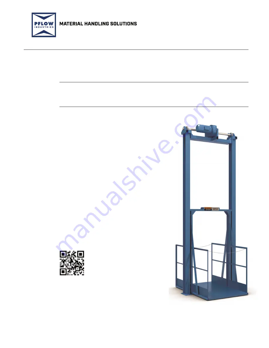
M Series | Mechanical VRC


Owner’s Manual 

with NORD Motordrive 

and Single or Twin Roller Guides

Customer:

Job Number:

Important:

Read this entire manual.  

Important safety information 

is included.

The illustrations depicted in this manual 

are not to scale or detail. The illustrations 

are for reference only.

www.pflow.com

P 414 352 9000

F 414 352 9002

6720 N. Teutonia Ave.

Milwaukee, WI 53209

Summary of Contents for F Series

Page 1: ...ingle or Twin Roller Guides Customer Job Number Important Read this entire manual Important safety information is included The illustrations depicted in this manual are not to scale or detail The illustrations are for reference only www pflow com P 414 352 9000 F 414 352 9002 6720 N Teutonia Ave Milwaukee WI 53209 ...

Page 2: ...ions 3 1 Obligation 3 1 Liability 3 2 Warranty Procedures 3 2 Pre Authorization 3 2 Invoices 3 2 4 Important Safety Information 15708 0200 01 4 1 Read the Entire Manual 4 1 Intended Purpose 4 1 Potential Risks and Possible Misuse 4 1 Safety Alert Symbols 4 1 Danger Statements 4 2 Warning Statements 4 2 Caution Statements 4 4 Electrical Safety Precautions 4 5 De energize the Circuit 4 5 Electrical ...

Page 3: ...2 Corrosive Application 6 2 Hazardous Location 6 3 Class Definitions 6 3 Division Definitions 6 3 Group Designations 6 3 7 Mechanical Overview 15705 1020 7 1 Lift Columns 7 1 Straddle and Cantilever Configuration 7 1 Drivebase Assembly 7 2 Safety Cam and Roller Guides 7 3 Safety Cam Function 7 5 Enclosures 7 6 Gate Assemblies 7 7 8 Electrical Overview 15709 0006 8 1 Main Control Panel 8 1 Push but...

Page 4: ...of the Brake 10 6 Brake Running Operation 10 7 11 NORD Motor Maintenance and Troubleshooting 15709 0090 11 1 Safety Warnings 11 1 Manual Release Identification 11 2 Brake Running Operation 11 3 Air Gap Values 11 3 Brake Maintenance 11 4 Adjust the Air Gap 11 4 Troubleshooting the Brake 11 5 Removing the Brake 11 6 Disposal of the Brake and Motor 11 6 Gearbox Lubrication 11 7 Lubrication Replacemen...

Page 5: ...rrent Sensor 15709 0052 15 1 16 Recommended Spare Parts 15705 1022 16 1 17 Parts 15705 1024 17 1 Drivebase Assembly 17 1 Chain Loop Arrangement 17 2 Chain Tensioner Assembly 17 3 Interlocks 17 4 Gate Status Switches 17 6 Safety Cam Assembly 17 7 Guide Roller Block Assembly 17 8 Twin Roller Guide Assembly 17 9 Single Roller Guides Assembly 17 12 18 Recommended Storage Requirements 15709 0080 2 18 1...

Page 6: ... mail psd pflow com Table of Contents www pflow com P 414 352 9000 F 414 352 9002 6720 N Teutonia Ave Milwaukee WI 53209 Bill of Material Sheets Document Option Drawings Descriptions Document Revision Customer Information Customer Name Job Number ...

Page 7: ...9002 6720 N Teutonia Ave Milwaukee WI 53209 Customer Information Customer Name Job Number Job Drawings Description Document Revision Electrical Drawings Description Document Revision Safety Data Sheets Description Document Copies of Safety Data Sheets are located on the PFlow website at https www pflow com knowledge base ...

Page 8: ...TOC 8 M Series 15705 1003 Rev A 2020 06 01 e mail psd pflow com Table of Contents www pflow com P 414 352 9000 F 414 352 9002 6720 N Teutonia Ave Milwaukee WI 53209 ...

Page 9: ...written permission from PFlow Industries Inc This publication may be photocopied by the original purchaser Any other type of reproduction is prohibited without express written permission from PFlow Industries Inc All trademarks referenced in this manual are the property of their respective owners Mechanical or electrical modifications performed on the equipment not approved by PFlow Industries Inc...

Page 10: ...6HFWLRQ _ _ 5HY _ _ H PDLO SVG SÁRZ FRP Section 1 Contact Information www pflow com P 414 352 9000 F 414 352 9002 6720 N Teutonia Ave Milwaukee WI 53209 ...

Page 11: ...e information and illustrations in this manual are intended only as an aid to understanding the VRCs general installation The information and illustrations do not cover every possible contingency or circumstance regarding nonstandard options or site conditions If there is a problem call PFlow Industries Inc at 414 352 9000 during normal business hours 8 30 a m to 5 00 p m central standard time Mon...

Page 12: ...Section 2 2 15710 0004 Rev C 2018 04 01 e mail psd pflow com Section 2 General Information www pflow com P 414 352 9000 F 414 352 9002 6720 N Teutonia Ave Milwaukee WI 53209 ...

Page 13: ...ity substitution of parts other than factory authorized parts removal of any parts or addition of any parts without prior written permission by PFlow Industries Inc 6 Any losses or damages resulting from loss of data loss of revenue or profits loss of products incidental or consequential damages delays or expenses incurred by failure of said part or parts even if advised of the possibility thereof...

Page 14: ...rtment prior to starting work z Where distance and or experience may be more cost effective PFlow Industries Inc reserves the right to use alternate organizations z Labor is defined as a maximum of two hours travel per call plus reasonable on site repair time as determined by PFlow Industries Inc z Local purchase of components must be pre authorized 1 Notify the PFlow Industries Inc Parts Service ...

Page 15: ...ned to understand the purpose limitations and associated hazards of the VRC Any other use is strictly forbidden PFlow Industries Inc has attempted to protect against as many hazards as possible The following potential risks should be addressed before the VRC is put into operation z Risk of injury caused by falling products z Risk of injury caused by product extending beyond the confines of the car...

Page 16: ...platform If a maintenance operation requires the carriage to remain in the raised position refer to Bulletin 15709 0083 for additional information or contact PFlow Industries Inc Product Support Department for assistance z Passengers are not permitted Riding may result in death or serious personal injury z This equipment can be dangerous if not used properly Allow only competent adults who have be...

Page 17: ...d Never leave the lift unattended with the gates in the open position Never close gates when a person is on the carriage or within the fenced area z Place the load in the center of the lift platform to avoid shifting loads Make sure that any portion of the load does not overhang the perimeter of the carriage This could create an unstable load condition z If the carriage deck does not stop after co...

Page 18: ... During operation the surfaces of some components may become hot Avoid touching hot surfaces or wear protective gloves z Inform personnel about the location and operation of emergency stops and power disconnection points z If any unsafe or unusual conditions are observed stop the equipment and remove it from service Report the condition to your supervisor CAUTION ...

Page 19: ...ltimeter or voltage sensing device Make sure the device is rated for the level of voltage being measured and is sensitive enough for the application 2 Use fuse pullers to change a fuse never use bare hands pliers or screwdrivers 3 Install covers on exposed electrical devices or wires to protect personnel from serious injury 4 Ground all metal connection boxes switch boxes starting boxes transforme...

Page 20: ...tes or bobby pins These items are electrically conductive and accidental contact may cause serious personal injury 3 Wear dry clothing and shoes Moisture should not be present on the soles of shoes Water is electrically conductive and accidental contact may cause death or serious personal injury 4 Insulate the worker from the ground Cover any adjacent grounded metal surfaces with an insulating mat...

Page 21: ...147 The Control of Hazardous Energy Lockout Tagout z z At least two 2 means of support are used to secure the raised platform The lifting systems can be used as one means of support provided that no work is to be done on the hydraulic system or mechanical drive system and an appropriate LOTO has been performed on the VRC Additional means of support include adequately sized maintenance chains maint...

Page 22: ...kout Tagout program 6 Secure the carriage at the upper level using adequately sized maintenance chains maintenance pins or straps with shackles around the drivebase that are capable of supporting the weight of the carriage to provide additional safety Do not attempt to do any work on the lifting system e g hydraulic system motor drive When work is to be done on the hydraulic system or mechanical d...

Page 23: ...d to perform a specific duty or duties The vertical portions of the carriage on a cantilever VRC typically a series D vertical support mast Also known as a Mezzanine roll off panel this is a panel that is installed opposite the loading edge at upper loading levels of a VRC platform that does not penetrate a floor The backstop panel helps protect personnel and or products from falling off the platf...

Page 24: ... VRC This normally includes push buttons relays limit switches interlocks etc An enclosure housing various electrical components that control the VRC The control voltage is typically provided by the control transformer and is used to energize the various low voltage electrical devices See Vertical Reciprocating Conveyor VRC A static load that is a permanent force acting on a structure see Platform...

Page 25: ...amel is viewed as insufficient An electrically powered single panel vertical acting gate A sheet of metal uniformly slit and stretched forming diamond shaped openings in the metal sheet Expanded metal is a one piece construction that will not unravel under normal circumstances and will hold its shape Expanded metal comes in a standard raised or flattened diamond pattern in a variety of gauges open...

Page 26: ...This minimizes wear points A device which converts fluid power into linear force and motion The hydraulic cylinder usually consists of a movable element such as a piston and piston rod plunger or ram operating within a cylindrical bore Refers to motor pump and reservoir assembly The reservoir is shipped with oil Most hydraulic power units come with the control panel attached and pre wired to the h...

Page 27: ...ixed position A push button which only has to be pressed for an instant to activate the desired operation The side s of a carriage not used for loading unloading Handrails or expanded metal sides and kick plate are normally supplied as minimum guarding The side s of the carriage used for loading unloading At a minimum the side s are normally equipped with a safety chain as guarding The outside dim...

Page 28: ... load A plastic prismatic object used to reflect a beam of light emitted from a photoelectric sensor See Back stop panel The type of chain drive most commonly used for transmission of mechanical power The roller chain consists of a series of short cylindrical rollers held together by side links and connecting pins The roller chain is driven by a toothed wheel called a sprocket Spring loaded harden...

Page 29: ...els that guide the carriage between the columns A single panel vertical acting gate A VFD is a type of drive used in electro mechanical drive systems to control AC motor speed and torque by varying the motor frequency and voltage A device that senses hydraulic flow across a control orifice when the pressure differential exceeds a predetermined amount A spring biased poppet closes shutting flow to ...

Page 30: ...he gates to swing open The VAC gate panel closes to the floor and opens in the upward direction The BVAC gate is the same as the single panel VAC above in operation and use except the two 2 panels telescope from a nested position The horizontal sliding gate operates in the same manner as a vertical acting gate except the gate functions in the horizontal direction The roll up door can be anything f...

Page 31: ... Teutonia Ave Milwaukee WI 53209 18613 0100 SMG PFL 200113 M Series Straddle Sprocket Drivebase assembly Lift chain Overtravel limit switch Guide column Column Upper limit switch Carriage header Safety cam Roller guides Carriage upright Carriage Roller guides Deck Platform Operating end Chain tensioner Landing ...

Page 32: ...52 9000 F 414 352 9002 6720 N Teutonia Ave Milwaukee WI 53209 PFL 200520 1 M Series Cantilever Sprocket Drivebase assembly Guide column Column Chain Tube Carriage back frame panel Safety cam Upper roller guide Carriage Carriage upright Lower roller guide Carriage deck plate Landing ...

Page 33: ...RQ _ Section 5 Glossary www pflow com P 414 352 9000 F 414 352 9002 6720 N Teutonia Ave Milwaukee WI 53209 Push button PB station Carriage header Interlock Gate header Gate panel Bi parting swing gate Gate post 13675 0002 SMG PFL 200115 3 ...

Page 34: ...6HFWLRQ _ _ 5HY _ _ H PDLO SVG SÁRZ FRP Section 5 Glossary www pflow com P 414 352 9000 F 414 352 9002 6720 N Teutonia Ave Milwaukee WI 53209 ...

Page 35: ... wire number from the electrical drawing using a machine or computer generated label utilizing black characters on a white background 5 All field devices must be individually terminated in the control panel 6 Screw on solderless connectors wire nuts shall be of the insulated type spring lock and of the proper size to accommodate wires 7 Terminal lugs shall be of the insulated type crimp style and ...

Page 36: ...th a focus on advancing and applying engineering knowledge and communicating the excitement of engineering This group is the Secretariat for ANSI National Electrical Code is an advisory board to NFPA with recommendations and codes usually adopted throughout the United States NEMA 12 classification is to be used in a general purpose indoor only application All PFlow Industries Inc control systems a...

Page 37: ...or ignitable mixtures Class II locations Locations that are hazardous because of the presence of combustible dust Class III locations Locations that are hazardous because of the presence of easily ignitable fibers or where materials producing combustible flyings are handled manufactured or used but in which such fibers filings are not likely to be in suspension in the air in quantities sufficient ...

Page 38: ...6HFWLRQ _ _ 5HY _ _ H PDLO SVG SÁRZ FRP Section 6 Electrical Standards DQG HÀQLWLRQV www pflow com P 414 352 9000 F 414 352 9002 6720 N Teutonia Ave Milwaukee WI 53209 ...

Page 39: ...uide angle welded to one flange of the column to form a track A chain tube guard is welded to the face of the other flange There are two 2 configuration types available for this model Straddle has a column located on each side of the carriage The guide angles face each other allowing the carriage to ride between them See Figure 7 1 Cantilever has both columns located at the back of the carriage Se...

Page 40: ...nsioner sprocket and back up to the carriage to fasten to a chain tensioner bracket shown in Figure 7 4 Item 5 The tensioner sprocket is spring loaded by the chain tensioner which maintains tension on the chain tensioner combination If the lift chain is pulled too tight or becomes slack the chain tensioner limit switch is activated to shut off power to the VRC The chain tensioner is adjusted at a ...

Page 41: ...gure 7 6 Cantilevers have four 4 single roller guide assemblies bolted to the carriage two on each side with the wheel riding within the column See Figure 7 7 and Figure 7 8 Safety Cam and Roller Guides 18613 0200 SMG PFL 200114 3 1 Jackscrew 2 Safety Cam Assembly 3 Twin Roller Guide Assembly 4 Carriage Upright 2 1 3 4 J18809 SMG PFL 200522 2 1 Jackscrew 2 Safety Cam Assembly 3 Roller Guide Assemb...

Page 42: ...guide angle to stop the carriage from falling The safety cam shoe on the outside of the guide angle track helps wedge the safety cam teeth See Figure 7 9 and Figure 7 10 Safety Cam Function 1 Lift Chain 2 Toggle 3 Connecting Link 4 Safety Cam 5 Safety Cam Shoe 18613 0100 SMG PFL 200115 3 2 1 4 5 1 Lift Chain 2 Toggle 3 Connecting Link 4 Safety Cam 5 Safety Cam Shoe 18613 0100 SMG PFL 200115 1 3 2 ...

Page 43: ...ure panels to be installed around the Vertical Reciprocating Conveyor VRC as required by site conditions The enclosure panels are steel with 1 1 2 38mm angle frame and 16 gauge flattened expanded metal designed to reject a ball 2 51mm in diameter PFlow Industries Inc standard enclosure panels are typically 8 tall 2438mm Full height enclosures FHE are furnished when designed for site specific requi...

Page 44: ...area are electromechanically interlocked When a gate or door is open the interlock prevents movement of the carriage away from the respective level When the carriage is not present at a level opening the gate or door is prevented by the mechanical interlock See Figure 7 12 PFlow Industries Inc offers various styles of interlocks depending upon the gate type and application The parts section of thi...

Page 45: ...ee WI 53209 Examples 1 2 3 4 1 2 3 4 1 Bi Panel Swing Gate 2 Single Panel Swing Gate 3 Vertical Acting Sliding Gate 4 Sliding Gate 15690 0002 S SMG PFL 1875 8 PFL 3076G 16520 1000 SMG PFL 1875 9 15690 0002 S SMG 15925 1000 SMG PFL 3061B Swing Gate Interlock Examples Figure 7 13 Peelle VAC Figure 7 14 Cable Actuator Figure 7 15 Anderson VAC Figure 7 16 ...

Page 46: ...6HFWLRQ _ 0 6HULHV _ _ 5HY _ _ H PDLO SVG SÁRZ FRP Section 7 Mechanical Overview www pflow com P 414 352 9000 F 414 352 9002 6720 N Teutonia Ave Milwaukee WI 53209 ...

Page 47: ...o more than 6 6 1981mm off the floor 1 3 2 9 10 8 7 4 6 15690 0008 S SMG PFL 1099 4 1 3 2 9 10 8 7 4 6 1 Drivebase Assembly 2 Second Level Push button Station 3 Overtravel Limit Switch 4 Second Level Limit Switch 5 Disconnect Switch 6 First Level Push button Station 7 Main Control Panel 8 First Level Limit Switch 9 Columns 10 Carriage 5 5 Electrical Components Figure 8 1 The following is a standar...

Page 48: ...nd brake wiring must be verified prior to energizing the VRC The M series VRC has five 5 limit switches incorporated into a standard two level VRC one 1 at each level to stop the carriage one 1 overtravel and two 2 chain tensioner switches All limit switches require field mounting and wiring VRCs servicing more than two levels require two 2 additional limit switches for each intermediate level Lim...

Page 49: ...he rated lift capacity z Make sure all safety devices are in place and operable before using the equipment If any safety device is missing or inoperable immediately remove the equipment from service z Falling hazard Always make sure the carriage is present before walking through doorways z Keep clear of unsupported platforms Stay out of the area under a raised platform If a maintenance operation r...

Page 50: ... circuit to the motor starter See Figure 9 2 This action turns the motor in the needed direction 2 The brake is released The motor turns the gears in the reducer which in turn rotates the keyed drive shaft The drive sprockets on the shaft turn resulting in the raising or lowering of the lift chains The lift chains are fastened to the safety cam assemblies which are bolted to the carriage uprights ...

Page 51: ...age The switch cuts the power to the motor circuit The motor starter contacts open the motor stops and the brake is applied This stops and holds the carriage position Before activating the VRC have a qualified electrical controls technician investigate why the uppermost floor level limit switch failed and correct the problem See Figure 9 4 Sequence continued Limit Switch Figure 9 4 Wheelblock Shoe...

Page 52: ...15 for more information 6 The chain tensioner limit switch is typically mounted at the bottom of the lift column If a lift chain becomes slack or are broken the chain tensioner limit switch will activate to shut off power to the motor and apply the brake The safety cam will rotate and set on the column The carriage will stop The VRC will not operate until the lift chain is repaired and the chain t...

Page 53: ...e desired floor level button to move the carriage to the desired floor The carriage will stop when the appropriate level is reached 3 When the VRC arrives at the appropriate level and comes to a complete stop open the gate 4 If an emergency occurs when the carriage is moving push the emergency stop E stop button The button will keep the lift inoperable until the button is pulled out See Figure 9 6...

Page 54: ...6HFWLRQ _ 0 6HULHV _ _ 5HY _ _ H PDLO SVG SÁRZ FRP Section 9 Sequence of Operation www pflow com P 414 352 9000 F 414 352 9002 6720 N Teutonia Ave Milwaukee WI 53209 ...

Page 55: ...es and information can be found at www nord com under the documentation tab NOTICE Working brake Brake which implements friction work in regular operation i e performs a braking function Brake Spring applied brake electromagnetically released spring applied brake Data sheet Technical data sheet Holding brake Brake which does not perform friction work during regular operation but holds the load in ...

Page 56: ...ynthetic Oil 105ºC 225ºF z In the following instances please consult PFlow Industries Inc Product Support Department for specific recommendations z Gear units will operate in high ambient temperature conditions exceeding 40ºC 104ºF z Gear units will operate in cold ambient temperature conditions approaching 0ºC 32ºF or lower z Lower than an ISO VG100 viscosity oil is being considered for a cold te...

Page 57: ...he EC Directive The lettering of the spring pressure brake includes important data This data and the contractual provisions for the brakes establish the limits of use Lettering on the brake housing 103V 12 09 40 Braking torque in Nm Year of manufacture Month of manufacture Operating voltage DC in Volt FDB 15 N H F R T S M 20 H7 24 VDC Operating voltage Hub bore Micro switch Dust guard ring Tapped ...

Page 58: ... 6720 N Teutonia Ave Milwaukee WI 53209 Reducer Nameplate NOTICE Observe the data on all reducer nameplates and verify published ratings for the NORD item s in question Do not operate any NORD equipment outside the published performance range Failure to comply may result in damage to the drive unit driven machine or the environment ...

Page 59: ...5XQ DS QFUHDVHG 6 EHB 6LQJOH 3KDVH 5XQ DSDFLWRU 2QO 3 SR LSSHG LQGLQJV ORZHU RROLQJ DQ SK DQG SK ORZHU RROLQJ DQ SK UDNH RFNDEOH 0DQXDO 5HOHDVH H QHUJ IÀFLHQW UDNH 0DQXDO DQG 5HOHDVH IG QFUHPHQWDO QFRGHU 3 3 QYLURQPHQWDO 3URWHFWLRQ IR UDNH XUUHQW 6HQVLQJ 5HOD KB RQGHQVDWLRQ ROHV 5HPRYDEOH 3OXJV RQGHQVDWLRQ ROHV 2SHQ MIK UDNH 0LFURVZLWFK 06 3RZHU 3OXJ RQQHFWRU 2 7 19 0RWRU LWKRXW DQ LWK RYHU 2 7 19...

Page 60: ...or the counter friction surface produces the braking torque During release a magnetic force is produced through applying a direct voltage to the magnet body item 1 1 1 2 via the field winding Said magnetic force draws the armature disk item 2 to the magnet body and the brake rotor is released During manual release only if brakes are designed with manual release the armature disk is mechanically pu...

Page 61: ...increases as the lining on the rotor wears The air gap must be verified in accordance with the following schedule unless a particular sensor for wear monitoring has been included in the brake Inspection intervals Working brake According to service life calculation According to specifications made by the customer Holding brake At least every two years According to specifications made by the custome...

Page 62: ...6HFWLRQ _ _ 5HY _ _ H PDLO SVG SÁRZ FRP Section 10 125 0RWRU GHQWLÀFDWLRQ DQG 2SHUDWLRQ www pflow com P 414 352 9000 F 414 352 9002 6720 N Teutonia Ave Milwaukee WI 53209 ...

Page 63: ...ivesystems instructions Additional resources and information can be found at www nord com under the documentation tab NOTICE Safety Warnings High Voltage Installation or maintenance work may only be performed when no power is available to the motor Electric motors electrical brakes and variable frequency drives contain potentially dangerous high voltage Shut down the power at the circuit breaker o...

Page 64: ...ally pulled against the magnet body by pulling the manual release handle item 5 with screwed in manual releasing lever item 5 1 and the rotor is released This enables you to release the brake even if there is a power failure CAUTION Carriage drop hazard For safety reasons the adjustment of the manual release must not bechanged Manual Release GHQWLÀFDWLRQ Release Direction 1 Magnet Body 5 Manual Re...

Page 65: ... accordance with the following schedule unless a particular sensor for wear monitoring has been included in the brake Inspection intervals Working brake At least every year According to specifications made by the customer Holding brake At least every two years According to specifications made by the customer Use shorter intervals in case of frequent emergency stops 1 Magnet Body 2 Armature Plate 1...

Page 66: ...osen the fastening screws item 11 by turning the fastening screws half a rotation counter clockwise 2 Turn the hollow screws item 12 counter clockwise into the magnet body 3 Turn the fastening screws clockwise into the motor flange until the nominal air gap is reached measured with a feeler gauge at three different positions around the brake See the previous page for the appropriate measurement 4 ...

Page 67: ...ease LU JDS LV WRR ODUJH QVSHFW DQG DGMXVW DLU JDS UDNH LV QRW VXSSOLHG ZLWK YROWDJH 9HULI HOHFWULFDO FRQQHFWLRQ 9ROWDJH DW WKH FRLO LV WRR ORZ 9HULI WKH VXSSO YROWDJH RI WKH FRLO UPDWXUH SODWH LV REVWUXFWHG 5HPRYH WKH REVWUXFWLRQ Brake release is delayed LU JDS LV WRR ODUJH QVSHFW DQG DGMXVW DLU JDS 9ROWDJH DW WKH FRLO LV WRR ORZ 9HULI WKH VXSSO YROWDJH RI WKH FRLO Brake does not apply 9ROWDJH DW...

Page 68: ...Ferrous metals key number 160117 z Non ferrous metals key number 160118 z Brake linings key number 160112 z Plastics key number 160119 High Voltage Employees servicing or maintaining VRCs may be exposed to death or serious personal injury if hazardous energy is not properly controlled De energize any circuit before work is begun Follow your facilities procedures or OSHA lockout tagout LOTO procedu...

Page 69: ...icant should be replaced at least after every 10 000 operating hours or after every two years If the gear unit is filled with synthetic oil the lubricant should be replaced at least after every 20 000 operating hours or after every four years Often gear reducers are exposed to extreme ambient conditions hostile environments wet conditions or dirty and dusty operating areas Especially in these situ...

Page 70: ... and reducer operating temperatures The user should consult with their lubrication supplier before considering changes in oil type or viscosity z To prevent reducer overheating observe the maximum operating oil temperature limits Mineral Oil 80 85ºC 176 180ºF Synthetic Oil 105ºC 225ºF z In the following instances please consult PFlow Industries Inc Product Support Department for specific recommend...

Page 71: ... z Food grade lubricants must be in compliance with FDA 212 CFR 178 3570 and qualify as a NSF H1 lubricant Please consult with lubrication manufacturer for more information z When making a lubrication change check with the lubrication supplier to assure compatibility and to obtain recommended cleaning or flushing procedures z Make sure not to mix different oils with different additive packages or ...

Page 72: ...ratio Prior to starting the reducer check the oil fill level using the reducer s oil level plug and drain or add oil as needed The minimum acceptable oil level is 0 15 4mm below the oil level hole For shipping purposes the larger gear units are supplied without oil Oil quantities shown are for the gearbox only When the OT oil tank option is used the oil must be filled to the level shown on the dip...

Page 73: ...nd Troubleshooting www pflow com P 414 352 9000 F 414 352 9002 6720 N Teutonia Ave Milwaukee WI 53209 Oil Plug RQQHFWLRQV Oil level for 3 stage gear units Verify the oil fill level using the dip stick located in the oil tank for the M4 H5 position Oil Plug Locations Figure 11 6 ...

Page 74: ...I WKH UHGXFHU 7LJKWHQ ORRVH EROWV DQG RU UHLQIRUFH PRXQWLQJ DQG VWUXFWXUH RRVH KROG GRZQ EROWV 7LJKWHQ EROWV Runs noisy Failure of bearings DFN RI OXEULFDQW 5HSODFH WKH EHDULQJ OHDQ DQG ÁXVK WKH UHGXFHU DQG ÀOO ZLWK WKH UHFRPPHQGHG OXEULFDQW 2YHUORDG 9HULI WKH UDWHG FDSDFLW RI WKH UHGXFHU Runs noisy Insufficient lubricant HYHO RI OXEULFDQW LQ UHGXFHU QRW SURSHUO PDLQWDLQHG 9HULI WKH OXEULFDQW OHYH...

Page 75: ...close gates when a person is on the carriage or within the fenced area z The most common reason for access to the area beneath the carriage is to remove debris from the pit This is best accomplished using a long handled broom or rake to avoid entering the pit under the raised carriage deck Only qualified person following proper lockout tagout procedures with the carriage properly secured in a rais...

Page 76: ...www pflow com P 414 352 9000 F 414 352 9002 6720 N Teutonia Ave Milwaukee WI 53209 _ 6HFWLRQ _ 5HY _ _ H PDLO SVG SÁRZ FRP Section 12 Cleaning VRC ...

Page 77: ...ity to solve problems relating to the subject matter and work NOTICE z z If any defects relating to operating safety and reliability are detected or if any damage occurs the VRC must be taken out of operation immediately z z Lockout tagout the VRC before performing maintenance on electrical components De energize any circuit before work is begun z z Take appropriate measures for safely working at ...

Page 78: ... lift tensioner gate with non detergent petroleum based SAE 30 oil Inspect for wear rust bent cracked or binding links 3 months Inspect limit switches and operation Adjust as necessary 3 months Verify that the chain sprocket position is centered over the chain tube Adjust the position if necessary Apply Locktite Blue 242 to the setscrew Tighten and torque setscrew 3 months Inspect all additional o...

Page 79: ...or national electrical codes Make sure the equipment is properly grounded in accordance with local electrical codes or in the absence of local codes with the current edition of the National Electrical Code NFPA No 70 z Keep clear of unsupported platforms Stay out of the area under a raised platform If a maintenance operation requires the carriage to remain in the raised position use a means of sup...

Page 80: ...WHG WR WKH PDLQ SRZHU IXVHV RU WKH FRQWURO IXVHV RUUHFW WKH SUREOHP DQG UHSODFH WKH IXVH 3RZHU FLUFXLW EHWZHHQ WKH GLVFRQQHFW DQG VWDUWHU LV GHDG 8VLQJ D YROWPHWHU PHDVXUH WKH YROWDJH 5HSDLU DV QHHGHG RRVH OLIW FKDLQ RU WHQVLRQHU FKDLQ 7LJKWHQ WKH FKDLQ RU DGMXVW WKH FKDLQ WHQVLRQHU RU FKDLQ VHQVRU URNHQ WHQVLRQHU FKDLQ 5HSDLU RU UHSODFH DV QHHGHG VZLWFK RQ WKH HFN RFN LV QRW IXQFWLRQLQJ SURSHUO Q...

Page 81: ...DQG FOHDQ WKH DUHD Rough or noisy operation QWHUIHUHQFH EHWZHHQ WKH FKDLQ DQG FKDLQ JXDUGV RU FKDLQ JXLGHV HWHUPLQH WKH FDXVH DQG FRUUHFW 6KDIW SLOORZ EORFN EHDULQJV DUH ZRUQ RU GU QVSHFW OXEULFDWH DQG UHSODFH DV QHHGHG 0RWRU UHGXFHU HWHUPLQH WKH FDXVH DQG FRUUHFW 7UDYHO LQWHUIHUHQFH GHQWLI WKH SUREOHP UHPRYH DQG UHSDLU DV QHHGHG ULYH FRPSRQHQW LQWHUIHUHQFH GHQWLI WKH SUREOHP UHPRYH DQG UHSDLU DV ...

Page 82: ...6HFWLRQ _ 0 DQG 04 6HULHV _ _ 5HY _ _ H PDLO SVG SÁRZ FRP Section 14 Troubleshooting www pflow com P 414 352 9000 F 414 352 9002 6720 N Teutonia Ave Milwaukee WI 53209 ...

Page 83: ...lfunction overloading the capacity of the lift or an overhanging load trapped between floors 1 Turn the trip point dial to its lowest position 2 Place the maximum product load on the carriage Overcurrent Sensor OCS Purpose Before You Begin Test and Calibrate the OCS Overcurrent Sensor Figure 21 1 Read this entire manual YES YES YES YES YES YES Run the carriage down Run the carriage up Run the carr...

Page 84: ...6HFWLRQ _ _ 5HY _ _ H PDLO SVG SÁRZ FRP Section Adjust Overcurrent Sensor www pflow com P 414 352 9000 F 414 352 9002 6720 N Teutonia Ave Milwaukee WI 53209 ...

Page 85: ...er 2 17545 0000 Roller Guide 1 25 OD 2 5221 0000 Bolt Shoulder 5 8 x 1 1 4 2 5874 0020 Roller Guide 1 25 OD 4 17539 0000 Bolt Shoulder 1 2 x 1 3 4 4 2503 0028 Push button Stations PB Station 2 LVL 22mm 1 13675 0002 Emergency Stop E Stop 1 13692 0014 Operator Push button Black Flush 1 13690 0003 General Paint 13 oz PFlow Blue Aerosol Spray 1 2871 0003 Electrical Components Fuse 0 8A 600V Class CC T...

Page 86: ...Section 16 Recommended Spare Parts M Series www pflow com P 414 352 9000 F 414 352 9002 6720 N Teutonia Ave Milwaukee WI 53209 2 Section 16 M Series 15705 1022 Rev 2020 01 15 e mail psd pflow com ...

Page 87: ...mbers Please send a photo of the SO number from the reducer assembly and have the PFlow serial number available when requesting this information Before You Begin Drivebase Assembly 15690 0005 S SMG PFL 20180816 2 1 3 4 5 1 Motor Brake Reducer Assembly 2 Driveshaft 3 Drive Sprocket 4 Bearing Pillow Block 5 Drivebase Weldment Part numbers in this manual are subject to change without notice Component...

Page 88: ... Consult PFlow Industries Inc Parts Department before ordering 2 3 4 5 1 10308 0002 SMG PFL 200115 3 3 4 2 7 8 6 Item Qty Part No Description 1 1 5667 0000 KDLQ 1 2692 0000 KDLQ 1 2693 0000 KDLQ 1 4102 0000 KDLQ 2 2 0DVWHU LQN KDLQ 2 0DVWHU LQN KDLQ 2 2523 0000 0DVWHU LQN KDLQ 2 0DVWHU LQN KDLQ 3 2 7651 0000 6ZLYHO 5RXQG H RXEOH 4 2 0DVWHU LQN KDLQ 5 2 KDLQ HQJWK 6 2 3715 0000 6µ RRN 7 2 6191 0000...

Page 89: ...ZLWKRXW LPLW 6ZLWFK 1 1 10244 0035 6SURFNHW DQG UDFNHW VVHPEO 1 10244 1000 6SURFNHW DQG UDFNHW VVHPEO 6 6 2 1 1XW 5 7KUHDG 3 1 2520 0000 7XUQEXFNOH 7HQVLRQHU 4 1 3732 0010 1XW 7KUHDG 5 1 LQN 7HQVLRQHU 6 1 5959 0007 UP LPLW 6ZLWFK PP RQJ 7 1 LPLW 6ZLWFK LPLW 6ZLWFK 6LQJOH 3ROH 6269 0000 LPLW 6ZLWFK RXEOH 3ROH LPLW 6ZLWFK 3 1 ROW LPLW 6ZLWFK 0RXQWLQJ 1 RFN DVKHU LPLW 6ZLWFK 0RXQWLQJ 1 DVKHU LPLW 6ZL...

Page 90: ...92 0300 RQWURO DEOH VVHPEO 1 9292 0360 RQWURO DEOH VVHPEO 2 1 5ROOHU UP VVHPEO 1 KHHO RQO 3 1 10170 0000 UDFNHW 0WJ RQWURO DEOH 4 1 WHQVLRQ 6SULQJ 5 1 10167 0000 3ODWH QWHUORFN DWH 9 6 1 9332 0009 6HW ROODU DEOH QWHUORFN 1 3694 0000 H ROW RQJ 1 H 1XW 3ODWHG 7 1 QWHUORFN QGHUVRQ 1 QWHUORFN QGHUVRQ 5 1 QWHUORFN QGHUVRQ DWHU 5HVLVWDQW 1 QWHUORFN QGHUVRQ 5 DWHU 5HVLVWDQW 1 4 QWHUORFN QGHUVRQ ZLWK 4XLF...

Page 91: ...ocks 1 2 13661 0000 SMG PFL 20180820 1 The interlock is a device used to mechanically prevent the gate from opening Below is the GAL interlock supplied As a safety device replacement components are only available as shown below Some configurations may vary by application Item Qty Part No Description 1 1 13660 0000 QWHUORFN 5 1 13661 0000 QWHUORFN 2 1 Keeper ...

Page 92: ...ch is supplied when the contact are not being used If required it will be mounted to the gate post or header Normally the GAL and Anderson interlocks do not use this switch Specific order requirements may differ Item Qty Part No Description 1 1 6220 0000 5ROOHU 3OXQJHU 3DUDOOHO 2 1 6216 0000 5ROOHU 3OXQJHU 3HUSHQGLFXODU 3 1 GMXVWDEOH 5ROOHU UP 4 1 6ZLWFK 15690 1001 SMG PFL 20180820 3 4 1 2 ...

Page 93: ...s HT Right hand 17550 0012 25 Columns HT Left hand 17550 1012 Item Qty Part No Description 1 2 3LQ OHYLV ROXPQ 2 2521 0000 3LQ OHYLV ROXPQ 2 2 LQN 6DIHW DP 2 LQN 6DIHW DP 7UHDWHG 3 2 2522 0000 3LQ RWWHU 4 4 6FUHZ U Item Qty Part No Description 5 6 RFN DVKHU 6WG 6 4 6296 0015 DVKHU 6WG ODW 7 2 6FUHZ U 1 2754 0000 6KRH 6DIHW DP 1 2767 0000 6SDFHU 6DIHW DP 6KRH ROXPQV 2 2767 0000 6SDFHU 6DIHW DP 6KRH...

Page 94: ...onia Ave Milwaukee WI 53209 17540 0000 PFL 200117 Gen 1 Gen 2 1 4 5 4 5 7 6 2 3 Item Qty Part No Description 1 1 ORFN XLGH 5ROOHU 2 1 9237 0040 ROW 5 3 1 RFN DVKHU 67 Item Qty Part No Description 4 1 17539 0000 5ROOHU XLGH 2 5 1 ROW 6KRXOGHU 6 1 ROW 6KRXOGHU 7 1 5221 0000 5ROOHU XLGH 2 Guide Roller Block Assembly 17540 0000 ...

Page 95: ...0 11 9 5 6 6 12 13 7 8 Item Qty Part No Description 1 4 6FUHZ 5 2 RFN DVKHU 6WG 3 6296 0015 DVKHU 6WG ODW 4 4 6FUHZ 5 5 2 17546 0000 3LQ PP 6 2 KHHO 1 RLO 7 4 6FUHZ 6 4 1XW RFN 1 ORQ 9 2 17545 0000 3ODWH 5HWDLQHU 10 3 9237 0024 6FUHZ 5 11 3 RFN DVKHU 6WG 12 1 17561 0000 DU ODPS 13 1 17540 0000 XLGH 5ROOHU ORFN VVHPEO 14 1 17543 0000 1 RLO KHHO VVHPEO 17543 0000 PFL 200120 2 14 17544 0000 Note Appl...

Page 96: ...s red LH 17544 1010 17544 0010 SMG PFL 200120 1 2 3 4 2 3 5 10 11 9 5 6 6 12 13 7 8 Item Qty Part No Description 1 4 6FUHZ 5 2 RFN DVKHU 6WG 3 6296 0015 DVKHU 6WG ODW 4 4 6FUHZ 5 5 2 17546 0000 3LQ PP 6 2 17376 0000 KHHO 3RO 7 4 6FUHZ 6 4 1XW RFN 1 ORQ 9 2 17545 0000 3ODWH 5HWDLQHU 10 3 9237 0024 6FUHZ 5 11 3 RFN DVKHU 6WG 12 1 17561 0000 DU ODPS 13 1 17540 0000 XLGH 5ROOHU ORFN VVHPEO 14 1 17543 ...

Page 97: ...scription 1 4 6FUHZ 5 2 RFN DVKHU 6WG 3 6296 0015 DVKHU 6WG ODW 4 4 6FUHZ 5 5 2 17546 0000 3LQ PP 6 2 KHHO 6WHHO 7 4 6FUHZ 6 4 1XW RFN 1 ORQ 9 2 17545 0000 3ODWH 5HWDLQHU 10 3 9237 0024 6FUHZ 5 11 3 RFN DVKHU 6WG 12 1 17561 0000 DU ODPS 13 1 17540 0000 XLGH 5ROOHU ORFN VVHPEO 14 1 17543 0200 6WHHO KHHO VVHPEO 17543 0200 PFL 200120 4 14 Twin Roller Guide Wheelblock Assembly RH 17544 0020 Steel Whee...

Page 98: ...541 0000 Nyoil Wheels green LH Upper 17541 1000 RH Lower 17542 0000 LH Lower 17542 1000 1 2 3 5 7 8 4 6 Item Qty Part No Description 1 4 6FUHZ 5 2 RFN DVKHU 6WG 3 6296 0015 DVKHU 6WG ODW 4 1 17540 0000 XLGH 5ROOHU ORFN VVHPEO 5 2 KHHO 1 RLO 6 2 17546 0000 3LQ PP 7 2 6FUHZ 6 2 17545 0000 3ODWH 5HWDLQHU 17541 0000 Note Apply moly coat grease to inside diameter of wheel prior to inserting pin 17542 1...

Page 99: ...Guide Wheelblock Assembly RH Upper 17541 0100 Poly Wheels red LH Upper 17541 1100 RH Lower 17542 0100 LH Lower 17542 1100 1 2 3 5 7 8 4 6 Item Qty Part No Description 1 4 6FUHZ 5 2 RFN DVKHU 6WG 3 6296 0015 DVKHU 6WG ODW 4 1 17540 0000 XLGH 5ROOHU ORFN VVHPEO 5 2 17376 0000 KHHO 3RO 6 2 17546 0000 3LQ PP 7 2 6FUHZ 6 2 17545 0000 3ODWH 5HWDLQHU 17541 0100 17542 1100 ...

Page 100: ...oller Guide Wheelblock Assembly RH Upper 17541 0200 Steel Wheels LH Upper 17541 1200 RH Lower 17542 0200 LH Lower 17542 1200 1 2 3 5 7 8 4 6 Item Qty Part No Description 1 4 6FUHZ 5 2 RFN DVKHU 6WG 3 6296 0015 DVKHU 6WG ODW 4 1 17540 0000 XLGH 5ROOHU ORFN VVHPEO 5 2 KHHO 6WHHO 6 2 17546 0000 3LQ PP 7 2 6FUHZ 6 2 17545 0000 3ODWH 5HWDLQHU 17541 0200 17542 1200 ...

Page 101: ...nt will require that the following maintenance procedures be performed every sixty days from date of shipment 1 If roller chains are stored for an extended period of time or in a corrosive environment they must be dipped or stored in a non detergent oil to retain their original condition 2 Lightly coat the sprockets with a non detergent oil to prevent corrosion 3 Lubricate the safety cams with a n...

Page 102: ...the PFlow Industries Inc Product Support Department for additional information that may be available prior to starting up your unit The VRC installation manual electrical and owner s manuals are located in the parts container crate Do not open the parts container crate If the manuals are required contact the PFlow Industries Inc Product Support Department for an electronic copy pdf Long Term Stora...

Page 103: ...s are not allowed The placement of capacity labels and safety warnings are the installer s responsibility Make sure the warning labels are placed on each gate and each push button station PFlow Industries Inc supplies the appropriate signage in a manilla envelope in the parts crate with the original shipment Contact PFlow Industries Inc Product Support Department for signage if another language is...

Page 104: ...Section 19 2 15709 0035 Rev C 2018 04 01 e mail psd pflow com Section 19 Signage Locations www pflow com P 414 352 9000 F 414 352 9002 6720 N Teutonia Ave Milwaukee WI 53209 ...

Page 105: ...ter the electrical installation was completed was it necessary to return for final adjustments testing and training Were you made aware of any electrical problems Describe any No answers areas in detail Testing Was the equipment tested at full load capacity Were all gates tested to ensure proper operation and interlock operation PFlow Industries Inc would like to thank you for the opportunity to s...

Page 106: ...15708 1500 Rev F 2018 04 01 e mail psd pflow com Section 20 Installation Questionnaire www pflow com P 414 352 9000 F 414 352 9002 6720 N Teutonia Ave Milwaukee WI 53209 ...

Page 107: ... If there are any exceptions or unresolved items please include detailed information Please return a copy of this form to the PFlow Industries Inc Product Support Department Acceptance PFlow Serial Number Model Number B D DB F M MQ 21 CV Other __________ Job Name Site Street Address Site Mailing Address Site City State Zip Code Customer Contact Name Contact Title Customer Contact Phone Ext E Mail ...

Page 108: ...15710 0017 VRC Rev D 2018 04 01 e mail psd pflow com Section 21 Acceptance Certification VRC www pflow com P 414 352 9000 F 414 352 9002 6720 N Teutonia Ave Milwaukee WI 53209 ...

Reviews: