

PAX TECHNOLOGY INC.
PAX TECHNOLOGY INC.
PAX TECHNOLOGY INC.
x
P
terminals
that
include
a
default
communication
module
come
standard
with
one
Ethernet
port
and
RS
232,
USB
,
and
PUSB
network
capabilities
.
However
,
if
the
default
communication
module
is
replaced
with
an
optional
communication
module
,
your
choice
of
these
additional
network
capabilities
are
available
:
Communication Module
Communication Module
Power Connections
Power Connections
3
Product Description
Product Description
• A second Et hernet port
• Po we r over Et hernet
• An Et hernet hub
• Wi -Fi and Bl uetooth LE
• Wi -Fi and Ce llular GS M
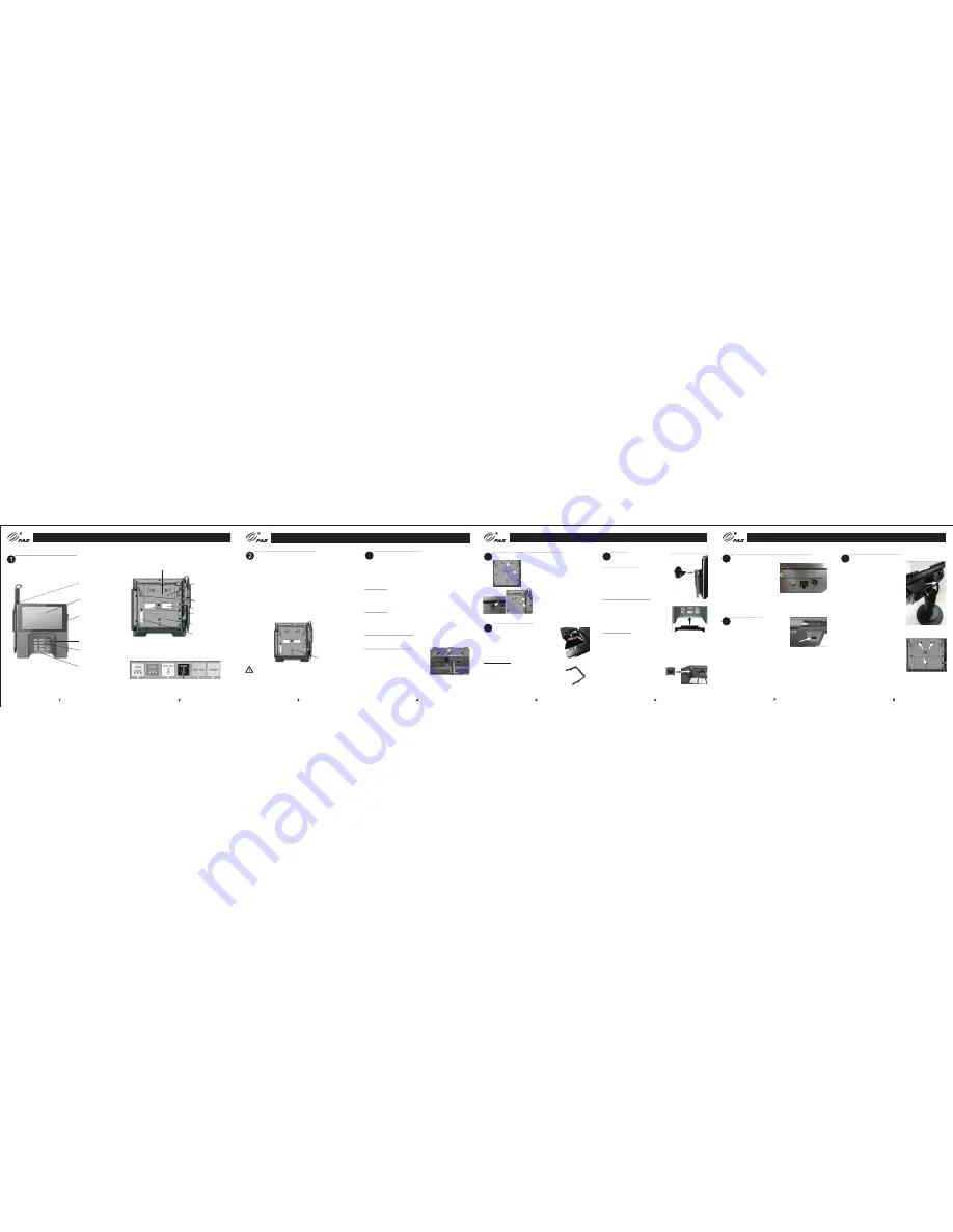
The commu nication mo dule is located on the underside of
the termi nal.
Communication
module
Power down and remove all power from the terminal before
removing or installing a communication module. A
communication module must be installed before power can be
applied to the terminal.
WARNING:
Working Environment: Temperature -10
°
C
~
50
°
C (14
°
F
~
122
°
F)
R
.
H
.:
10%
~
93% (non-condensing)
Storage Environment: Temperature
-
20
°
C
~
60
°
C (-4
°
F
~
140
°
F
)
R
.
H
.:
5%
~
95%
(
non-condensing)
Stylus pen
Touch screen
and
Contactless
reader area
Magnetic
stripe reader
Privacy shield
Keypad
Smart card
reader
Cable retention
cover plate
Communication
ports - located
under cover plate
Speakers
MAC address label
Regulatory label
Communication
module
Communication ports are labeled and color-coded:
White Red Yellow Black
Green
Blue
Part number/
serial number label
Power can be supplied via the power port or a single data cable
that carries power. This power can be provided via a “powered
cable” where the connected POS terminal provides the power
x
(i.e. PUSB or Power over Ethernet) or by connecting a P power
supply directly to the data cable (i.e. RS232 or USB).
1) Power Port
Insert the power connector into the green POWER port. Turn
the power connector, locking the tab behind the short plastic
wall. Dress the cable through the retention clips. A separate
data cable is also required.
2) POS Cable
Insert the cable connector into the appropriate port on the
terminal. Dress the cable through the retention clips opposite
the port. Connect power supply to cable as required. The cash
register could also supply power to terminal.
3) Power over Ethernet (PoE)
Power is available over the red LAN1 port when the optional
PoE communication module is installed.
Cable Retention Cover Plate
After power and data cables are
connected and dressed through
retention clips, install the cable
retention cover plate and secure
with captive screw.
Screw
Stylus Holder and Pen
Stylus Holder and Pen
4
1)
Mo unting
Locations
2)
Stylus
Port
3
)
Re tention
Cl ips
1) Align stylus holder over
metal screw openings at left
side or top of terminal. Insert
tabs into indentations along
edge. Attach with captive
screws.
2) Insert connector end of
stylus pen into stylus port on
left side of terminal.
3) Use enclosed plastic card to
press stylus cord into retention
clips on left side of terminal.
Privacy Shield
Privacy Shield
5
Insert tabs and snap shield firmly in place
to left and right of keypad. Not designed to
be removable. Removing the shield breaks
the retention tabs and the ability to remotely
track the status of the shield is lost.
1
Privacy Shield
Decorative Plug
Decorative Plug
–
If a privacy shield is not
installed, a non-removable decorative plug
may be installed in its place. This plug does
not provide any PIN entry privacy.
CAUTION
:
If the privacy shield is not installed,
you must use PCI-approved alternative methods
to secure the PIN pad.
Plugs
Plugs
6
1) Stylus Holder Plug
If required, to prevent stylus pen from
being inserted vertically into stylus
holder, firmly insert plug into opening
in holder, aligning with curve of stylus
holder.
2) Smart Card Reader Plug
If required, insert smart card reader
plug into smart card receptacle slot.
To remove, if required, gently pry out
the plug using a small screwdriver in
the slit along top of plug.
3) Ethernet Plug
An Ethernet plug is included in case
you want to block an inactive LAN port.
Align plug so that it matches the shape
of the port and gently push into opening.
To remove, if required, gently pry off
using a small screwdriver in the slit
along the top of the plug.
Note: LAN2 port is enabled only when
Ethernet hub or PoE and Ethernet hub
communication module is installed.
1) Stylus
Holder
Plug
2) Smart Card Reader Plug
3) Ethernet
Plug
Mounting
Slots
Stand Installation
9
Stand Installation
PAX TECHNOLOGY INC.
Route
Cables
x
If required, the P
terminal may be
mounted to a stand
.
Instructions
may
vary depending
on stand specifications
.
Carefully route the required cables
up through the stand pipe and out
the top. Connect the cables to the
x
P terminal ports.
Insert the three mounting slots on
the underside of the terminal into
the three metal prongs on the stand
base.
Slide the terminal firmly into position,
locking the terminal in place on the
stand. Secure with fastening screw
or locking device as required.
Reset Button and Audio Jack
7
Reset Button and Audio Jack
Reset
Button
Audio Jack
If required, restart the
terminal by pressing in
and holding the reset
button for 2-3 seconds
If required, a visually disabled person can connect a
headphone to the terminal for audio prompting using the
3.5mm output audio jack.
Cable Lock
8
Cable Lock
If required, insert customer-provided
cable lock into K-Slot®. Loop cable
around permanent object to secure
in place.
Stylus Port


