background image


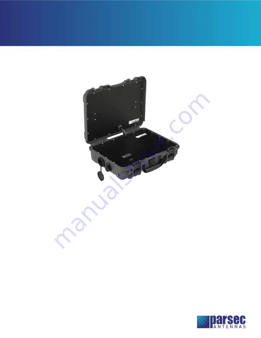
The Beagle is a low-profile, five-in-one MIMO LTE, MIMO WIFI, and GNSS antenna built into an IP67-rated* 
enclosure. This rugged, low-profile, omni-directional antenna works on most of the common North 
American LTE bands with high efficiency. The Beagle is optimized for LTE isolation.  


Table of Contents 

Antenna Versions ........................................................................................................................................................................................ 2


Required Tools & Accessories ................................................................................................................................................................ 2


Battery and Router Installation ............................................................................................................................................................. 3


Connection ..................................................................................................................................................................................................... 5


Final Assembly ............................................................................................................................................................................................ 10


Operational Setup ..................................................................................................................................................................................... 13


Battery Operation and Safety Guidelines....................................................................................................................................... 16


BEAGLE 

Installation Instructions 

* Conditions apply 

Summary of Contents for Beagle G

Page 1: ... works on most of the common North American LTE bands with high efficiency The Beagle is optimized for LTE isolation Table of Contents Antenna Versions 2 Required Tools Accessories 2 Battery and Router Installation 3 Connection 5 Final Assembly 10 Operational Setup 13 Battery Operation and Safety Guidelines 16 BEAGLE Installation Instructions Conditions apply ...

Page 2: ...ack Flat Head Machine Screws 4 pcs Ethernet Cords 2 pcs USB A Cord Battery Tray for ChargeTech 27K Battery Pack Cable Ties NEMA Male to Female Adapter PTA0071B Black Round Head Screws 18 pcs PTA0368 B Black Flat Head Machine Screws 4 pcs Ethernet Cords 2 pcs Cable Ties To Be Purchased By Customer 27K AC Battery Pack ChargeTech CT 600061 USB A Cord Ethernet Cords 2 pcs Ethernet Cords 2 pcs NEMA 5 1...

Page 3: ...late onto the battery tray and fasten with the six PTA0368 B black flat head machine screws provided in the kit as shown in Figure 2 If the battery tray does not align perfectly with the cover plate partially tighten the screws at opposite diagonal positions first then install all other screws before fully tightening It may help to install the screws in the order shown in Figure 2 Figure 1 Place t...

Page 4: ...ter orientation is correct as shown in the images below C Fasten the router to the cover plate using the four PTA0368 B black flat head machine screws provided in the kit as shown in Figures 3 and 4 D Guide the cable bundles back through the holes in the cover plate Figure 3 Fasten the router to the cover plate using PTA0368 B screws Beagle L Figure 4 Fasten the router to the cover plate using PTA...

Page 5: ...Beagle Installation Instructions Page 5 of 17 Connection Figure 5 Connection Diagram for Beagle G ...

Page 6: ...Beagle Installation Instructions Page 6 of 17 Figure 6 Connection Diagram for Beagle L ...

Page 7: ...ct the antenna cables to the designated terminals on the router as shown in the tables and images below Cradlepoint IBR600 and IBR900 Cradlepoint R500 PLTE Antenna Cable Router Terminal Antenna Cable Router Terminal LTE 1 MAIN PLTE 1 MAIN LTE 2 AUX PLTE 2 AUX GPS GPS GPS GPS WIFI 1 2 4 5GHz left WIFI 1 2 4 5GHz left WIFI 2 2 4 5GHz right WIFI 2 2 4 5GHz right Figure 7 Cradlepoint IBR600 IBR900 R50...

Page 8: ...This step only applies to the Beagle G B Plug the USB A cord from the fan into the USB A port on the router shown in Figure 7 Step 4 Connect the router to the RJ 45 ports on the case using ethernet cords A Connect the provided ethernet cords to the LAN port and WAN port on the router shown in Figure 7 B Connect the other ends of the ethernet cords from the router to the RJ 45 ports on the case Kee...

Page 9: ...he case and the USB A port on the battery pack shown in Figure 9 Step 6 Connect the battery pack to the DC charging port on the case Beagle G only A This step only applies to the Beagle G B Connect the DC charging port cable from the case to the DC charging port on the side of the battery pack shown in Figure 9 Figure 9 ChargeTech 27K Battery Pack Connections Beagle G AC Outlet AC Output Switch DC...

Page 10: ...very cable connection and ensure that no connections are loose B Use cable ties or other wire management to neatly bundle the cables Pack the cables neatly inside the bottom half of the case Ensure that the antenna cables are not excessively bent 1 2 minimum bend radius Figure 10 Fully Connected 5in1 Beagle G with Cradlepoint IBR900 Router ...

Page 11: ...Beagle Installation Instructions Page 11 of 17 Figure 11 Fully Connected 5in1 Beagle L with Cradlepoint IBR900 Router ...

Page 12: ... plate onto the bottom half of the case Ensure that no cables are pinched between the cover plate and the case B Fasten the cover plate to the case using the eighteen PTA0071B black oval head screws provided in the kit as shown in Figure 12 Figure 12 Fasten the cover plate to the case using PTA0071B screws ...

Page 13: ...2C 2G below C Turn the battery pack ON by pressing and holding the power button for 3 seconds The display on the battery pack will indicate the battery pack s current battery life Do not hold the button for longer than 3 seconds this will cause the battery pack to enter programming mode To exit programming mode turn the battery pack OFF then ON again D Set the AC output switch on the battery pack ...

Page 14: ...t on the router Step 4 Login to Cradlepoint NetCloud A Open a web browser on the computer and type 192 168 0 1 into the address bar This will bring up the Cradlepoint NetCloud login shown in Figure 14 B Login to Cradlepoint NetCloud The username is admin and the password is found on the router shown in Figure 15 Figure 14 Access Cradlepoint NetCloud Figure 15 Cradlepoint NetCloud Login Password ...

Page 15: ...ET and then CONNECTIONS B In the Device List table select the option with a cellular SIM as shown in Figure 16 Figure 16 Select the device with a cellular SIM in Cradlepoint NetCloud Antenna setup is complete For best antenna performance operate the antenna with the lid closed and the case oriented with the lip on top If applicable make sure the fan and vent caps are open while using the antenna ...

Page 16: ...e and the entire unit will stay ON until manually turned OFF F While plugged in and charging the battery pack will allow pass through charging to continue powering any devices that are plugged in to the battery pack To disable this function press and hold the power button for 2 seconds while the battery pack is charging Repeat to re enable pass through charging for all ports G Warning if the batte...

Page 17: ...thin 24 inches of the antenna Install the antenna or mast assembly on a windy day Install the mast close to power lines as it can cause serious injuries or death WARNING This document gives the detailed instructions to install an antenna to the best of our knowledge This document is for general information only It cannot be used as a warranty Parsec Technologies Inc will not accept any liability f...

Reviews: