CommScope ValuLine VHLP 3 Series, Installation Instructions Manual
The CommScope ValuLine VHLP 3 Series is a cutting-edge product designed to enhance your network infrastructure. With its user-friendly installation, you can quickly and easily set up your network system. To get started, simply download the free Installation Instructions Manual from our website, and unleash the full potential of your network.
Share
Download


Reviews:
No comments
Related manuals for ValuLine VHLP 3 Series

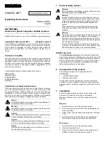
602 319-001
Brand: Hirschmann Pages: 2

RF300 Mk II-A
Brand: LAPLACE INSTRUMENTS Pages: 32

ANT 033
Brand: Williams Sound Pages: 4

137CP14HD
Brand: M2 Antenna Systems Pages: 7

ANT1538BK
Brand: THOMSON Pages: 38

35.7-4
Brand: M2 Antenna Systems Pages: 5

SIMATIC NET ANT897-4MC
Brand: Siemens Pages: 4
SIMATIC NET ANT895-6ML
Brand: Siemens Pages: 2

SIMATIC NET ANT896-4MA
Brand: Siemens Pages: 4

ANT795-4MB
Brand: Siemens Pages: 4

SIMATIC RF615A
Brand: Siemens Pages: 34

ANT795-4MA
Brand: Siemens Pages: 4

7LF4 941-5
Brand: Siemens Pages: 3

SIMATIC NET ANT795-6MT
Brand: Siemens Pages: 60

ANT792-6MN
Brand: Siemens Pages: 32

ANT793-8DK
Brand: Siemens Pages: 46

6GK5795-6MN10-0AA6
Brand: Siemens Pages: 44

ANT793-6DG
Brand: Siemens Pages: 58


