Parkside PMFS 200 B2, Translation Of The Original Instructions
The Parkside PMFS 200 B2 product manual is essential for understanding how to maximize the performance of your tool. Get the best usage out of your equipment by downloading the free Translation Of The Original Instructions manual at manualshive.com. Ensure a successful operation with clear, easy-to-follow instructions.
Share
Download


Reviews:
No comments
Related manuals for PMFS 200 B2

PW5001C
Brand: Makita Pages: 3

PV7001C
Brand: Makita Pages: 2

M9204
Brand: Makita Pages: 6

PV7000C
Brand: Makita Pages: 15
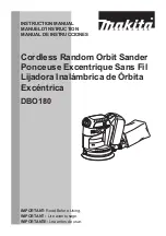
DBO180
Brand: Makita Pages: 28

BO5031
Brand: Makita Pages: 32

BO5020
Brand: Makita Pages: 36

BO5010
Brand: Makita Pages: 2

BO4900V
Brand: Makita Pages: 3

BO4900V
Brand: Makita Pages: 14

9227CY
Brand: Makita Pages: 28

9227C
Brand: Makita Pages: 3

9032
Brand: Makita Pages: 9

SA4540C
Brand: Makita Pages: 12

SUPREME MGP34
Brand: Shoe Systems Plus Pages: 18

OS-150
Brand: IVT Pages: 76

ULTRAPOL Advance
Brand: ULTRA TEC Pages: 40

65812
Brand: Wen Pages: 20


