background image

FOR TECHNICAL SUPPORT www.panduit.com/resources/install_maintain.asp

INSTRUCTIONS FS149A

© Panduit Corp. 2020

Page 1 of 19

HD Flex Zone Raised Floor Enclosure and Accessories

Part Numbers: FLEX-ZRFEG, FLEX-ZRFECG, FLEX-ZRFEDCG, FLEX-ZRFEWPG

Required

Tools

1.0 Enclosure Installation:

Mounting Depth Table

*10mm Socket

(

4) Support Brackets, with

Washers and Nuts

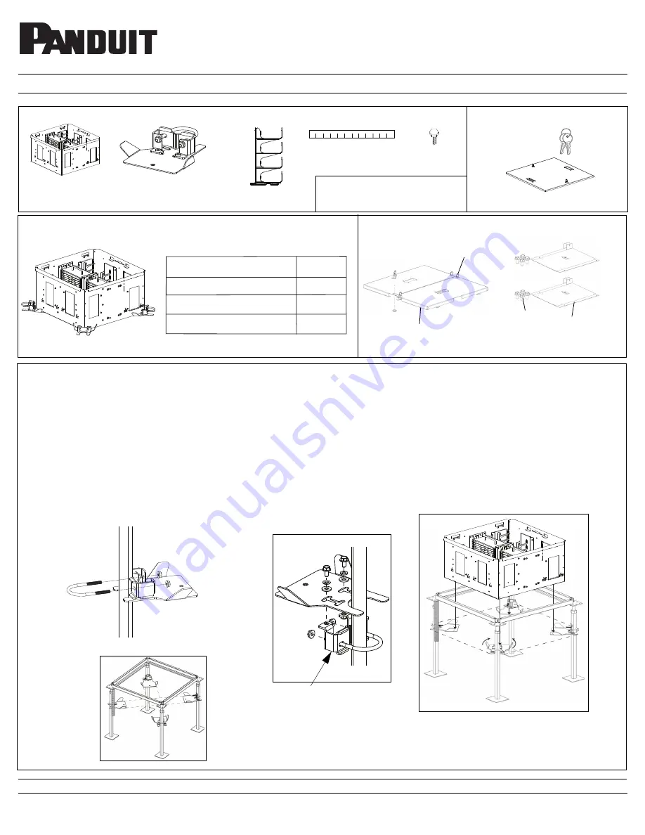
1. Select the installation location ensuring there are no obstacles to interfere with the installation.

2. Mount the four support brackets under the enclosure by placing one on each pedestal mount bracket by attaching the U-bolt and nut
around the pedestal (See Figure 2.1). Refer to Figures 3.1 through 3.3 for adjustment to various pedestal sizes. Use the magnetic ruler to
measure the correct mounting location for each support bracket. Point them towards the center making a cross from the corners (See Fig-
ure 2.2). Ensure that the plate is allowed to pivot from side-to-side.

NOTE:

If Grid Runner is placed above pedestal plate, then the mount-

ing assembly must be removed from plate and reconnected with the mounting assembly under the pedestal plate (See Figure 2.3).

FLEX-ZRFEG

Figure 2.1

Figure 2.2

Figure 2.4

(1) Lockable Enclosure Cover

(1) Set of Keys

Distance from bottom of pedestal head

plate to top of mounting brackets.

(

4) Bonding

Bolts

Optional Component 1: FLEX-ZRFECG

(

1) Magnetic Ruler

(+ .25” Tolerance)

Mounting assembly connected
under pedestal mount plate.

Figure 2.3

*7/16” Socket

Part Number

FLEX-ZRFEG

Mounting Bracket Depth Below Floor

12”

With Optional Cover 

14”

Enclosure Load Rating

54 lb

(1) Enclosure

The following items are included with FLEX-ZRFEG

.

FIgure 1

(2) Sets of Keys

(2) Lockable
Enclosure Covers

(8) Screws

(2) Partiton
Walls

Optional Component 2:
FLEX-ZRFEDCG

Optional Component 3:
FLEX-ZRFEWPG

(4) 4RU Cable
Managers

Summary of Contents for FLEX-ZRFEG

Page 1: ...t Point them towards the center making a cross from the corners See Fig ure 2 2 Ensure that the plate is allowed to pivot from side to side NOTE If Grid Runner is placed above pedestal plate then the mount ing assembly must be removed from plate and reconnected with the mounting assembly under the pedestal plate See Figure 2 3 FLEX ZRFEG Figure 2 1 Figure 2 2 Figure 2 4 1 Lockable Enclosure Cover ...

Page 2: ... 2 of 19 Installation of Pedestal Mount Assembly to Various Pedestal Sizes 3 The FLEX ZRFEG may be mounted to 7 8 square or up to 2 diameter round pedestals by adjusting the engagement of the U Bolt Figure 3 1 Figure 3 2 Figure 3 3 7 8 square pedestal 1 1 2 diameter pedestal 2 diameter pedestal ...

Page 3: ...wering the opposite side on the pedestal mounting brackets to manually align the four corners and mounting hole locations See Figure 4 1 and 4 2 5 Once all four corners and mounting holes are aligned in the correct orientation See Figure 5 1 fasten the enclosure to the pedestal mount ing brackets using the supplied M6 X 12mm bonding bolts See Figure 5 2 Installation continued Figure 4 1 Figure 4 2...

Page 4: ...THE LASER OFF WHEN IT IS NOT IN USE OR IS LEFT UNATTENDED FOR A PERIOD OF TIME REMOVE THE BATTERIES WHEN STORING FOR AN EXTENDED PERIOD OF TIME TO AVOID DAMAGE TO THE TOOL SHOULD THE BATTERIES DETERIORATE NEVER LOOK INTO THE PATH OF THE VISUAL FAULT LOCATOR OR ANY OTHER LASER BEAM NEVER LOOK INTO THE END OF A FIBER WHICH MAY HAVE ANY VISUAL FAULT LOCATOR OR ANY OTHER LASER COUPLED TO IT NEVER LAUN...

Page 5: ...rt cassettes See Figures 37 through 39 for installation of 4 port and 6 port rails for use with 4 port and 6 port cassettes Figure 8 Figure 9 Page 5 of 19 Figure 6 Table 1 MAXIMUM MODULE POPULATION PER ENCLOSURE 4 PORT MODULES 6 PORT MODULES 12 PORT MODULES FLEX ZRFEG 72 48 24 5 Patch Panel REAR Connector Installation a Route fiber bundle of 72 fibers cable through brushes in adjacent opening Loop...

Page 6: ... Mate MPO connectors from fiber cable to rear of cassettes starting from the bottom Bundle strands together with hook n loop See Figure 10 Figure 10 hook n loop Figure 12 Figure 11 c Install remaining MPO connectors into rear of cassettes working from the bottom upwards See Figures 11 through 12 Page 6 of 19 ...

Page 7: ...Route cables through 1st bottom position in 4RU cable canager Secure cables to 4RU manager 1st position with hook n loop See Figures 14 through 15 Figure 16 Figure 17 1st bundle of 72 fiber cables 2nd bundle of 72 fiber cables 3rd bundle of 72 fiber cables 4th bundle of 72 fiber cables c Route 2nd fiber bundle of 72 fiber cables through brushes in opening as shown Bring fiber bundle up towards the...

Page 8: ... cable up by bundles towards patch panel Route bundle 3 through 4RU cable manager position 3 Route bundle 4 through top position 4 in 4RU cable manager Secure fiber cable bundles with hook n loop See Figures 17 through 19 slots on both sides of the middle rail Figure 20 e Secure bundle 4 to slots on the middle rail see Figure 20 using hook n loop f Attach all of the fiber cables to each other with...

Page 9: ... 23 Figure 24 Fasten all fiber cable bundles together with one hook n loop g Grab handle and rotate patch panel downward ensuring that no fiber cables are pinched See Figure 25 Page 9 of 19 h Populate patch panel on the opposite side in the same manner described in steps 5 a through 5 g Figure 25 ...

Page 10: ...s for ease of editing and label replacement when necessary The labeling location on top is PANDUIT Part 00053EEF which is removable Labeling See Figure 27 The labeling layout for the patch panel see Figure 27 below for typical application PANDUIT label part C061X030FJJ can be used for single port identification PANDUIT label part C125X030FJJ for 2 port applications PANDUIT label part C252X030FJJ f...

Page 11: ...rs 0 0 0 5 3 E E F 1 2 3 4 5 6 7 8 9 10 11 12 13 14 15 16 17 18 19 20 21 22 23 24 25 26 27 28 29 30 31 32 33 34 35 36 37 38 39 40 41 42 43 44 45 46 47 48 49 50 51 52 53 54 55 56 57 58 59 60 61 62 63 64 65 66 67 68 69 70 71 72 73 74 75 76 77 78 79 80 81 82 83 84 85 86 87 88 89 90 91 92 93 94 95 96 97 98 99 100 101 102 103 104 105 106 107 108 109 110 111 112 113 114 115 116 117 118 119 120 121 122 1...

Page 12: ...ee Figure 29 Disconnect trunk cable from the rear of the cassette and con nect it to the rear of the replacement cassette Re install cas sette or MPO FAP opposite the way it was removed Align the rear of the cassette or MPO FAP in the opening and push inward until the cassette snaps into position near the front center until it clicks into place Re attach patch cords for cassette changes See Figure...

Page 13: ...mages shown in top view for clarity From the rear of the patch panel select the FAP to add additional MPO trunk cables to Insert the MPO connector into the rear of the FAP diagonally between the posts Step 1 in Figure 32 Push connector in until the rear of the boot just passes the rear post and lift the cable over the post to hold the connector in place Step 2 in Figure 32 Move to the front of the...

Page 14: ...ay Once the rail is fully re inserted the front of the rail will snap into position Pull forward on the rail to ensure it is properly installed While continuing to apply downward pressure on the rail being installed push the rail backward shown in Figure 35 As the rail begins to move it will engage with the tray The posts on the bottom of the rail will drop into the cutouts in the tray As the rail...

Page 15: ...gurations Only patch panel trays are shown for clarity 12 Port Configuration no removable rails installed on tray See Figure 37 6 Port Configuration 1 black removable rail per tray See Figure 38 4 Port Configuration 2 white removable rails per on tray See Figure 39 Page 15 of 19 FIgure 37 Figure 38 Figure 39 ...

Page 16: ...en suc cessfully attached drop the cover into the enclosure as shown See Figures 41 through 42 Option 1 HD Flex Zone Raised Floor Enclosure Cover FLEX ZRFECG Enclosure s Cover Installation Attach Adhesive Foam Seal to the top of the enclosure shown in Figure 40 Foam Seal Figure 40 Page 16 of 19 ADDITIONAL PRODUCTS SOLD SEPARATELY ...

Page 17: ...all Partition FLEX ZRFEWPG Lift up and remove both patch panels Secure partition walls with a total of 8 screws provided in the circled locations shown below in Figure 45 Install 4RU cable managers into sides of enclosure Re install patch panels per FIgure 46 Ensure patch panels are in the proper orientation shown Figure 45 Page 17 of 19 Front of Patch Panel 1 Front of Patch Panel 2 Figure 46 Inst...

Page 18: ...ble bundle 1 and working upward to cable bundle 4 Secure each bundle to the 4RU cable manager with hook n loop as shown in Figure 48 Page 18 of 19 Secure cables at rear of cassette through mounting holes in side of wall shown in Figure 47 with hook n loop BUNDLE INSTALLATION SEQUENCE OF CABLES AT FRONT OF CASSETTE 3 C Cable Installation at Front of Cassette Install cassettes and cables at rear of ...

Page 19: ...ch cassette routed to the left down and then to the right through the 4RU cable manager as shown in Figure 49 Rotate the patch panel mak ing sure that the fiber cables do not interfere with hit the enclosure Figure 50 Grab patch panel handle and rotate patch panel downward ensuring that no fiber cables are pinched Final Assembly shown with par tition walls and one dual cover installed See Figure 5...

Reviews: