background image

Before attempting to connect or operate this product,

please read these instructions carefully and save this manual for future use.

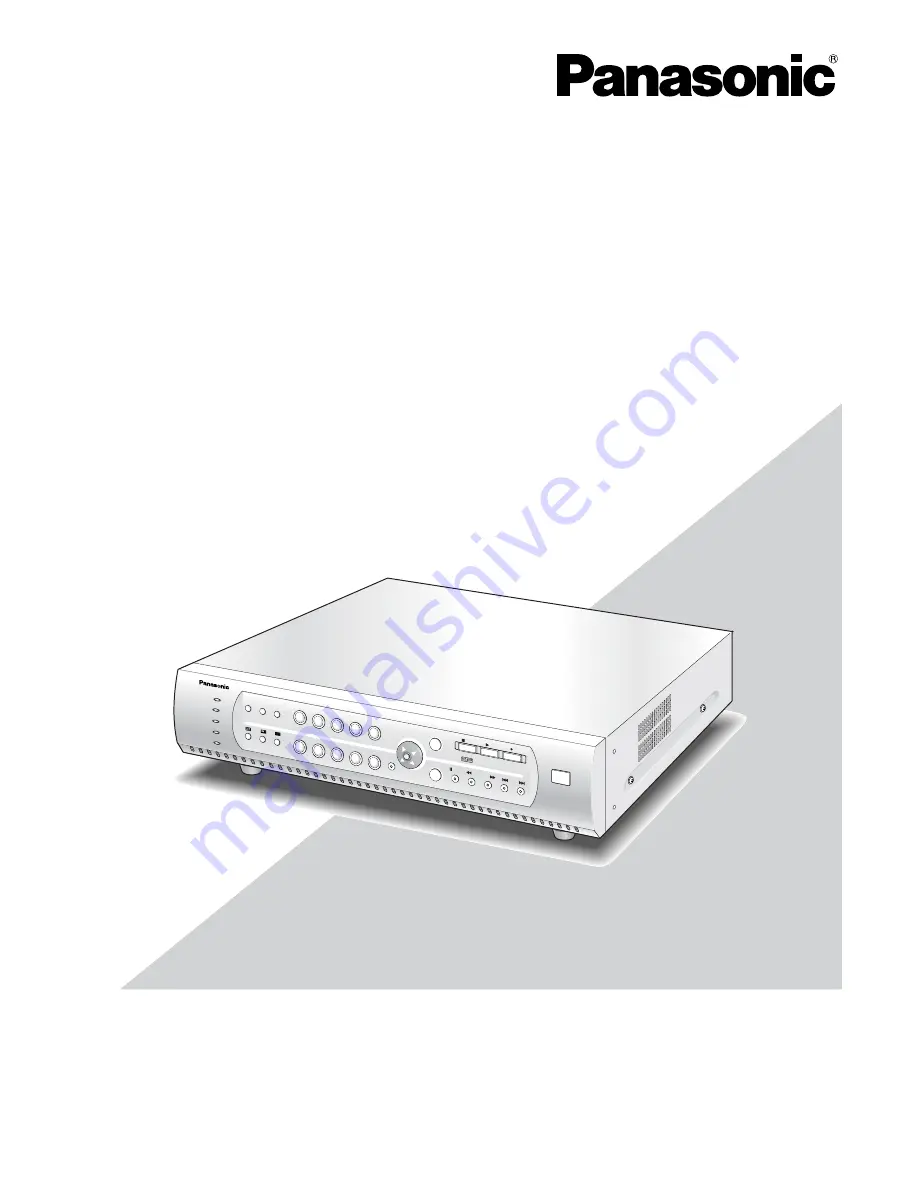
Digital Disk Recorder

Operating Instructions

Model No.

WJ-RT208

ERROR

ALARM

HDD

TIMER

1

2

3

4

5

6

7

8

9

0

MENU

ESC

ALARM

RESET

SEQUENCE

STILL

COPY 2

SET

PAUSE

REV

FWD

SKIP

STOP

PLAY

REC

Digital Disk Recorder WJ-R

T

OPERATE

208

Summary of Contents for WJRT208 - Digital Disk Recorder

Page 1: ...uctions carefully and save this manual for future use Digital Disk Recorder Operating Instructions Model No WJ RT208 ERROR ALARM HDD TIMER 1 2 3 4 5 6 7 8 9 0 MENU ESC ALARM RESET SEQUENCE STILL COPY 2 SET PAUSE REV FWD SKIP STOP PLAY REC Digital Disk Recorder WJ RT OPERATE 208 ...

Page 2: ...ion of this equipment in a residential area is likely to cause harmful interference in which case the user will be required to correct the interference at his own expense FCC Caution To assure continued compliance example use only shielded interface cables when connecting to com puter or peripheral devices Any changes or modifications not expressly approved by the party responsible for compli ance...

Page 3: ... your outlet consult an electrician for replacement of the obsolete outlet 10 Protect the power cord from being walked on or pinched particularly at plugs convenience receptacles and the point where they exit from the apparatus 11 Only use attachments accessories specified by the manufacturer 12 Use only with the cart stand tripod bracket or table specified by the manufacturer or sold with the app...

Page 4: ...IM ITATION DIRECT OR INDIRECT SPECIAL CONSE QUENTIAL OR EXEMPLARY ARISING OUT OF OR RELATING TO THE PRODUCT 2 PERSONAL INJURY OR ANY DAMAGE CAUSED BY INAPPROPRIATE USE OR NEGLIGENT OPERATION OF THE USER 3 UNAUTHORIZED DISASSEMBLY REPAIR OR MODIFI CATION OF THE PRODUCT BY THE USER 4 INCONVENIENCE OR ANY LOSS ARISING WHEN IMAGES ARE NOT DISPLAYED DUE TO ANY REASON OR CAUSE INCLUDING ANY FAILURE OR P...

Page 5: ...t panel Other names of companies and products contained in these operating instructions may be trademarks or reg istered trademarks of their respective owners Network Operating Instructions PDF Refer to the Network Operating Instructions PDF for descriptions of how to operate this unit using a PC Adobe Reader is required to read the Network Operating Instructions PDF When the Adobe Reader is not i...

Page 6: ...ns 8 Front View 8 Rear View 10 Installation 11 Installing the Hard Disk 11 System Composition and Connections 14 Basic System 14 Network System 16 Setup Procedures 22 1 Preparation 22 2 Operation 26 3 Setup 32 System Screen Explanations 49 Setup Menu Parameters and Initial Setup Values 50 Operation using the system controller 56 Troubleshooting 58 Specifications 59 Basic Specifications 59 Table of...

Page 7: ...ion Up to 8 hard disks can be installed 2 hard disks factory installed WJ RT208 Live monitoring Single channel live monitoring CH 1 8 1 4 6 9 split screen Camera control Recording mode Manual recording Timer recording Power on auto recording Terminal recording Motion detection VMD recording Recording quality frame rate stream type setup Compression methods Video MPEG 4 Audio ADPCM Playback mode Si...

Page 8: ...ture o Sequence Button SEQUENCE Runs the assigned sequence on the monitor screen for the specified duration Pressing this button starts stops the sequence 0 4 split Screen Button Pressing this button splits the screen into four segments displaying the surveillance pictures on Channels 1 to 4 Pressing the button again displays the next four surveil lance pictures on Channels 5 to 8 1 6 split Screen...

Page 9: ...ection area it is used to change the points describing the detection area 8 Stop Button STOP Pressing this button for two seconds stops recording In playback mode pressing this button stops playback 9 Play Button PLAY Pressing this button plays back the images recorded on the current channel When this button is pressed in pause mode the next frame will be displayed When this button is pressed whil...

Page 10: ... also used to connect component cameras with the RS485 protocol feature 1 VGA Output Port MONITOR VGA When a VGA monitor is connected to this port the same image as supplied from the video output terminal is obtained 2 Video Output Connector VIDEO OUT Spot live split screen and playback pictures are output from this BNC connector All menu settings and screen display information are also output fro...

Page 11: ...bject to vibration Installing the Hard Disk There is space for up to 8 hard disks The unit is provided with four IDE interfaces allowing installation of up to eight hard disks 1 Turning off the power Please check the rear of the unit and confirm that the power switch is turned off the power cord has been disconnected and the OPERATE indicator is off 2 Remove the top cover Remove four screws on the...

Page 12: ...s to IDE port 0 2 and 3 6 in total make the top one the Master and the bot tom one the Slave see Figs 3 and 5 Note Port 0 was installed to the two disks installed model Port 0 and 1 were installed to the four disks installed model For the relation between hard disk positions refer to the figure above or the explanation on hard disk management on page 47 5 Insert the hard disk into the hard disk fi...

Page 13: ...s on the motherboard with the correspondingly numbered hard disk connectors For the relation between hard disk positions refer to the figure above or the explanation on hard disk management on page 47 8 Follow the same procedure to install other hard disks Note Up to eight hard disks can be installed 9 Replace the top cover Refer to Fig 1 10 For formatting hard disks refer to page 47 of these Oper...

Page 14: ...ing Instructions refer all work relat ed to the connection of this product to qualified service personnel or system installers Basic System Example for Basic System Connections Basic Connection Cautions q Camera cable length BNC is a maximum of 500 m w The audio signals from a microphone are firstly amplified at the amplifier and then fed to the WJ RT208 14 System Composition and Connections Camer...

Page 15: ... be used RS485 Camera TERMINAL IN RS485 ALARM OUT WJ RT208 12V GND 8 GND 7 COM3 6 NC3 5 NO3 4 COM2 3 NC2 2 NO2 1 COM1 RB NC1 RA NO1 TB GND TA TERMINAL CONTROL interface ERROR ALARM HDD TIMER OPERATE 1 2 3 4 5 6 7 8 9 0 MENU ESC ALARM RESET SEQUENCE STILL PAUSE REV FWD SKIP STOP PLAY REC COPY 2 SET Digital Disk Recorder WJ RT 208 208 ...

Page 16: ...RIAL MONITOR VGA TERMINAL CONTROL AUDIO OUT VIDEO OUT AC IN SIGNAL GND POWER 1 1 2 2 3 3 4 4 5 5 6 6 7 7 8 8 ON OFF VIDEO IN AUDIO IN Digital Disk Recorder WJ RT 208 208 Windowsxp Microsoft IP Address 192 168 0 88 Subnet Mask 255 255 255 0 IP Address 192 168 0 x except 0 88 and 255 Subnet Mask 255 255 255 0 PC AT Compatible LAN cable Not provided 10Base T 100Base Tx Category 5 Cross ERROR ALARM HD...

Page 17: ...2 3 4 5 6 7 8 9 0 MENU ESC ALARM RESET SEQUENCE STILL PAUSE REV FWD SKIP STOP PLAY REC COPY 2 SET Digital Disk Recorder WJ RT 208 208 WAN Windowsxp Microsoft PC AT Compatible Server Port 2000 changeable Alarm Port 4000 changeable Forward WAN DVR UDP Port 9998 fixed TCP Port 2000 depends on the recorder settings Broadband router A Forward WAN PC UDP Port 999 fixed TCP Port 4000 depends on the recor...

Page 18: ... TERMINAL CONTROL AUDIO OUT VIDEO OUT AC IN SIGNAL GND POWER 1 1 2 2 3 3 4 4 5 5 6 6 7 7 8 8 ON OFF VIDEO IN AUDIO IN This unit 1 ON 2 Mode switch A B 1 3 2 4 6 5 7 9 8 0 SYSTEM CONTROLLER Controller Termination ON Unit address 1 RS485 cable provided with the controller MODE DATA 10 100BASE T COPY1 SERIAL MONITOR VGA TERMINAL CONTROL AUDIO OUT VIDEO OUT AC IN SIGNAL GND POWER 1 1 2 2 3 3 4 4 5 5 6...

Page 19: ... unit this unit Unit address system 5 Second unit Unit address system 6 RS485 cable RS485 cable RS485 cable RS485 cable Mode switch Mode switch When using WJ MP204 MODE DATA 10 100BASE T COPY1 SERIAL MONITOR VGA TERMINAL CONTROL AUDIO OUT VIDEO OUT AC IN SIGNAL GND POWER 1 1 2 2 3 3 4 4 5 5 6 6 7 7 8 8 ON OFF VIDEO IN AUDIO IN MODE DATA 10 100BASE T COPY1 SERIAL MONITOR VGA TERMINAL CONTROL AUDIO ...

Page 20: ...2 Terminal input 3 Terminal input 4 Terminal input 5 Terminal input 6 Terminal input 7 Terminal input 8 12 V Grounding Alarm Output 1 N O Alarm Output 1 N C Alarm Output 1 Common Alarm Output 2 N O Alarm Output 2 N C Alarm Output 2 Common Alarm Output 3 N O Alarm Output 3 N C Alarm Output 3 Common Grounding Grounding Sends the alarm signal to external alarm unit 2 Sends the alarm signal to externa...

Page 21: ...ermination switches The dip switch positions are defined by the attribute of the unit connected to the system s DATA terminal Refer to the label in regard to setting the DIP termination switches on the rear panel Caution Switch 2 of the DIP termination switch is not available 1 2 Machine connected to the DATA port Controller Termination switch 1 ON Termination switch 2 OFF ...

Page 22: ...then press the SET button When log in is successful the indicator of the direction button lights up This indicator is not lit up if log in has not yet been performed or has failed In the case of failure in log in the system presents an error dialog box Press the SET button or the ESC button to close the error dialog box Note The default passwords are set as below Manager 888888 Operator 88888 View...

Page 23: ...T SYSTEM LOG EVENT LOG OLDEST DATA INFORMATION USER INFORMATION USER LEVEL SETUP ONLINE USER INFORMATION PASSWORD KEYLOCK DATA MANAGEMENT FACTORY DEFAULT BACKUP SEARCH 0 Channel No CAMERA SETUP 1 Channel No On CH Enable Set Mask Area Off Mask Enable PANASONIC PTZ Protocol 000 All OK Cancel Rec Reserve Channel Name CH1 Days 2004 10 10 11 30 30 Start 2004 10 10 11 30 30 End No OK Cancel Event Only A...

Page 24: ...n Used to save the settings return to the previous menu or move to the setup dialog box Move the cursor to SET and press the button ESC button Used to clear the settings or return to the previous menu 0 9 button Used to enter numerical inputs 24 Off Power On Rec NTSC Video Format All Status Display On Keylock Buzz Off Pre Recording 04 I Frame Inter Off OK Cancel Alarm Spot N O Terminal Input 05 Se...

Page 25: ...n the rear panel Turn off the power supply after confirming that the HDD indicator of the front panel is not lit Check the OPERATE indicator If this indicator is not lit the power supply has been turned off Note If this unit is not used for a long time pull out the power cord from the power connector 1 4 Modification of the System Time When this unit is used for the first time set up the system ti...

Page 26: ...n 2 Press the REC button The indicator of the corresponding camera button is lit and recording is started The recording icon is displayed on the selected channel 3 Select the desired channel to be stopped by using the camera selection button 1 8 or the direction button up down to stop the recording Hold down the STOP button for 2 seconds The indicator of the corresponding camera button is unlit an...

Page 27: ...the PLAY button is pressed during playback slow playback starts The speed of slow playback is half that of ordinary playback 2 4 Operations for Events 2 4 1 Event type Terminal Alarm An event input to be entered from a sen sor to the TERMINAL port of this unit Motion Detection An event to sense and record the move ment of an object with the aid of the motion detector function refer to Cautions bel...

Page 28: ... the menu shown below WJ RT208 SETUP MENU REC EVENT TERMI NAL REC and WJ RT208 SETUP MENU REC EVENT VMD REC Period1 or Period2 On Buzzer The ALARM indicator blinks when an alarm is activat ed and this buzzer sounds The buzzer is set up with the menu specified below WJ RT208 SETUP MENU SYSTEM MANAGEMENT SYSTEM SETUP Alarm Buzz On An alarm signal output is generated from the TERMI NAL CONTROL port o...

Page 29: ...Iris control mode Note For some types of cameras some controls many not function Refer to the relevant operat ing instructions of the camera and confirm whether this unit is enabled to support controls and connections 2 5 1 Panning Tilting 1 Select the desired channel by using the direction button or numeric button The image frame of the selected channel blinks Select the pan tilt control mode by ...

Page 30: ... home position 1 Press the SET button once to select the required cam era control mode An icon is displayed on the screen of that channel according to the selected camera control mode 2 The camera returns to the home position by pressing the STOP button Notes 1 For the settings of the camera home position refer to the operating instructions for the camera 2 If the camera is not a Panasonic the pre...

Page 31: ... Playback and downloading of the recorded data Setup of this unit Event notification Alarm Automatic time and date adjustment 2 6 2 Computer configuration A computer with the configuration specified below is rec ommended If a computer other than the recommended one is used some problems may arise including software not starting delayed screen display and operation failures Notes If the Graphic Mem...

Page 32: ...P PTZ selection PTZ SELECT PRESET INFORMATION PTZ preset position check CAMERA SETUP Camera connection check and protocol settings COMMUNICATION SETUP Settings for network IP address gateway etc NETWORK SETUP RS485 SETUP Settings for RS485 communication DATA PORT SETUP Settings for serial data communication REPORT SYSTEM LOG EVENT LOG OLDEST DATA INFORMATION USER INFORMATION USER LEVEL SETUP Opera...

Page 33: ...EARCH REC EVENT SETUP PTZ SETUP CAMERA SETUP COMMUNICATION SETUP REPORT USER INFORMATION DATA MANAGEMENT SYSTEM MANAGEMENT SYSTEM SETUP DISK INFORMATION REBOOT SYSTEM PICTURE ADJUST TIME DATE VERSION Off Power On Rec NTSC Video Format All Status Display On Keylock Buzz Off Pre Recording 04 I Frame Inter Off OK Cancel Alarm Spot N O Terminal Input 05 Seq Dwell On Overwrite 600 Keylock Time Sec Sec ...

Page 34: ...face When an alarm goes off the screen of the occurring alarm is displayed in the single spot mode When the setting is made at VBR there may be a difference in recording length If the recording time need be in higher preference the setting should be made at CBR If screen changes seem to be extreme the set ting made at VBR is preferable N O Alarm is started with a low level signal N C Alarm is star...

Page 35: ... with the direction button right left Note During playback on Channel 1 the screen setup cannot be used 5 When adjustment is completed move the cursor to Return and press the SET button The newly set conditions are saved Note When PICTURE ADJUST is selected in a chan nel where no input signals are available Time date TIME DATE Refer to 1 4 for the system s time period Version VERSION 1 Press the M...

Page 36: ...NU button WJ RT208 SETUP MENU appears Move the cursor to REC EVENT SETUP and press the SET button Refer to steps 1 and 2 in 3 1 3 2 Move the cursor to TERMINAL REC and press the SET button 3 1 2 Record search SEARCH Refer to 3 2 3 1 3 Recording event setup REC EVENT Timer recording TIMER REC 1 Press the MENU button WJ RT208 SETUP MENU appears 2 Move the cursor to REC EVENT SETUP and press the SET ...

Page 37: ...l Stream type CBR VBR Default CBR If screen changes seem extreme the setting made at VBR is preferable Period Period1 Period2 Default 00 00 24 00 When On is selected for Period1 and or Period2 alarm detection will be validated in the set period Notes 1 When setting is completed set Period1 and or Period2 at On 2 For All operation and functions refer to the timer recording explanation 4 When settin...

Page 38: ...d2 to On 2 For All operation and functions refer to the timer recording explanation 3 When setting is completed move the cursor to Ok and press the SET button VMD Area Setup AREA SETUP 1 Move the cursor to OK and press the SET button in the VMD REC menu A motion detector area setup screen is displayed 2 Areas in green and without color are displayed on the screen In the green area the motion detec...

Page 39: ...posi tion number by using the numeric buttons Call Move the cursor to Call and press the SET but ton The camera turns to the preset position of the selected number Note For PTZ preset position setting refer to 2 5 6 3 When confirmation is completed move the cursor to Return and press the SET button 3 1 5 Camera setup CAMERA SETUP 1 Press the MENU button WJ RT208 SETUP MENU appears 2 Move the curso...

Page 40: ...mode changeover by pressing the SET button moving the red and black cursors at the same time or mov ing the black cursor only b When Numeral 1 is pressed the profile of the mask ing area is displayed When 2 is pressed all the area is embedded 3 1 6 Communication setup COMMUNICA TION SETUP Network setup NETWORK SETUP Move the cursor to COMMUNICATION SETUP on WJ RT208 SETUP MENU and press the SET bu...

Page 41: ...Parity Select a method to check a transmission error at com munication from the following None No parity check Even Even parity Odd Odd parity Stop Bit Select a stop bit from the following 1 bit 2 bit Retry Timing Select a retransmission interval for when data reception is not confirmed from the following OFF 100 ms 200 ms 400 ms 1 000 ms Alarm Data Select a method to inform the connected controll...

Page 42: ...em controller first When connecting the system controller with multiple recorders and is it necessary to change the camera number settings select Disable for the set association setting of the selected camera number before changing the cam era number settings Refer to the operating instructions of the system controller for further information about the associa tion settings between the camera numb...

Page 43: ...T button Press the direction buttons right left to changeover to the required camera number or update the user level of the operator and viewer If the user level of the operator or viewer is set at No for a channel that operator or viewer cannot watch that channel image However audio will not be ruled by these settings Cautions 1 User level higher than your own level cannot be modified 2 In regard...

Page 44: ...l password setting Keylock KEYLOCK 1 Move the cursor to KEYLOCK on the USER INFOR MATION menu and press the SET button The confir mation dialog box will be displayed Notes 1 The level for key lock operation stays at the same level for the Viewer If Live Viewer of the channel in the USER LEVEL SETUP menu is set at No key lock will be made and the screen will not be displayed 2 In the case of key lo...

Page 45: ...ack will not stop even when the key lock operation is carried out during playback If you leave this unit for a long time you should stop playback to maintain security 3 3 Backup by External HDD This unit can record a data backup with an external HDD including a 2 5 inch external hard disk Usually an exter nal hard disk can be used In order to avoid data loss due to hard disk malfunction or sudden ...

Page 46: ...memory unit 3 For backup image playback it is necessary to use the NetClient USB Client software on the accesso ry disc For the usage method refer to the Network Operating Instructions 1 Press the MENU button WJ RT208 SETUP MENU appears Move the cursor to DATA MANAGEMENT and press the SET button The DATA MANAGEMENT menu is displayed 2 Move the cursor to BACKUP and press the SET but ton The SEARCH ...

Page 47: ...num ber In screen display the hard disk position is indicated by two digits Example A B 0 1 A This is the hard disk position number in the diagram above 0 1 2 3 B Indicates the distinction between Master HDD 0 and Slave HDD 1 Regarding 0 1 for example it denotes the Slave HDD located in Position 0 Note If Master and Slave HDD are vertically connected in the same position both hard disks may become...

Page 48: ...he SET button The DATA MANAGEMENT menu is displayed 3 Move the cursor to FACTORY DEFAULT and press the SET button The confirmation dialog box will be displayed 4 Move the cursor to OK and press the SET button Recovery is started for the default settings configura tion Caution Except for the system time all the setting val ues are restored to the default settings WJ RT208 SETUP MENU SYSTEM MANAGEME...

Page 49: ...n a channel NO SIGNAL is displayed at the bottom left of the screen CH1 CH2 CH3 CH4 CH5 CH6 CH7 CH8 2004 11 04 16 00 00 Hard disk volume prompt Mute System time Previous channel Channel name CAM1 MANUAL NQ PLAY 2004 11 03 15 00 00 Playback time Playback status Record Playback the record Terminal recording Timer recording VMD recording Sequence display Iris adjustment Network Connections Pre record...

Page 50: ...e 600 005 999 Keylock Buzz On Off On Alarm Buzz Off Off On Pre Recording Off Off On Rec Quality Normal SP Fine Fine Good Normal Extended I Frame Inter 04 01 15 Resolution 800 x 600 800 x 600 1024 x 768 Alarm Spot Off Off On Stream Type CBR CBR VBR Alarm Input N O N O N C Frame Rate Full Full 1 2F 1 4F 1 8F 1 16F Possible displayed contents No disk detected Disk not format Disk access error Disk fa...

Page 51: ...Terminal Input Alarm Output Alarm Time Rec Interval PTZ Preset Default setting 1 0 030 060 000 Available values 1 8 0 3 000 999 030 999 000 256 Rec Channel 1 0 8 Rec Quality Normal SP Fine Fine Good Normal Extended Frame Rate Full Full 1 2F 1 4F 1 8F 1 16F Stream Type CBR CBR VBR Period1 00 00 00 00 24 00 24 00 00 00 24 00 Off Off On Period2 00 00 00 00 24 00 24 00 On 00 00 24 00 Off On Channel Re...

Page 52: ...utput Alarm Time Default setting 1 10 0 030 Available values 1 8 01 99 0 3 000 999 Rec Interval 060 030 999 PTZ Preset 000 000 256 Rec Quality Normal SP Fine Fine Good Normal Extended Frame Rate Full Full 1 2F 1 4F 1 8F 1 16F Stream Type CBR CBR VBR Period1 00 00 00 00 24 00 24 00 00 00 24 00 Off Off On Period2 00 00 24 00 Off 00 00 24 00 00 00 24 00 Off On Setting item Record Length Default setti...

Page 53: ...eway Server Port Protocol Alarm Center IP Default setting 192 168 000 088 255 255 255 000 192 168 000 001 2000 TCP 192 168 000 188 4000 Off Auto Mode 001 000 000 000 255 255 255 255 000 000 000 000 255 255 255 254 001 000 000 000 255 255 255 255 1024 9999 TCP UDP MCAST 001 000 000 000 255 255 255 255 1024 9999 Off On Auto Mode 10M Half 10M Full 100M Half 100M Full Setting item Baud Rate Data Bit P...

Page 54: ...m Modify Timer Rec Modify VMD Rec Modify Terminal Rec Modify Network Modify Manager Pswd Modify Operator Pswd Modify Viewer Pswd Restore Default Set Possible displayed contents Ch n VMD alarm Port n terminal alarm Cam n loss signal Cam n get signal Possible displayed contents Format Disk m Repair Directory Disk m Disconnect User n R Control User Login R Video User Login R Update Sys Settings R Mod...

Page 55: ...TORY DEFAULT 9 2 Search BACKUP Setting item Channel No Operator Live Viewer Operator Playback Viewer Live Viewer Viewer Playback Default setting 1 Yes Yes Yes Yes Available values 1 8 Yes No Yes No Yes No Yes No Viewer Operator Manager Default setting 8888 88888 888888 Available values 0 999999 0 999999 0 999999 Setting item Channel No Start End Event Only Default setting 0 No Available values 0 8...

Page 56: ...ssible to display the System Setup 301 submenu by pressing the F1 button while holding the SHIFT but ton down SHIFT F1 MENU F1 F2 Open the SETUP MENU Close the SETUP MENU 1 2 CAM SET or CAM SET or MON ESC SHIFT ALARM ALM SUSPEND REC RECSTOP REC RECSTOP PLAY PAUSE STOP Change the set parameter Enter a value Change the cursor position Press a button on the pop up menu Press a button on the pop up me...

Page 57: ...split screen It is possible to stop the sequential display by pressing the TOUR SEQ GROUP SEQ button while hold ing the SHIFT button down SHIFT TOUR SEQ GROUP SEQ Camera selection buttons 1 2 8 Press D or C Camera number MON ESC 5 CH number Camera selection buttons 1 2 8 5 CAM SET Camera number Pause the displayed image After displaying the Max Still 305 submenu of the WV CU650 Only clockwise rota...

Page 58: ...es are some times distorted during playback Response is delayed when text is displayed buttons are pressed or the VMD function is activated Is the power cord connected to the power outlet of this unit No camera images are dis played Is the camera lens dislodged Is the power supply turned ON for the camera and connected devices Is the cable connected correctly Are the screen setup parameters correc...

Page 59: ... interface RS485 x 1 25 pin D sub Data interface RS485 x 1 RJ 11 Data backup interface High speed serial interface front panel x 1 rear panel x 1 0 8 Mbps to 1 3 Mbps of transfer rate depending on recorder operating state HDD interface 4 IDE interfaces are incorporated capable of installing eight hard disks Function Video compression mode MPEG4 CBR fixed bit stream VBR variable bit stream Audio co...

Page 60: ...andard Accessories CD ROM 1 pc Operating Instructions This Document 1 pc Note The files specified below are included on the CD ROM Network Operating Instructions pdf Net Client software The following are for installation Power cord 1 pc HDD mounting screw WJ RT208K 32 pcs WJ RT208 24 pcs Recording mode 30 frames sec Image quality Super fine Fine Good Normal Extended HDD capacity 250 GB 3 4 5 7 16 ...

Page 61: ...61 ...

Page 62: ...ny of Panasonic Corporation of North America Security Systems www panasonic com security For customer support call 1 877 733 3689 Executive Office Three Panasonic Way 2H 2 Secaucus New Jersey 07094 Zone Office Eastern Three Panasonic Way Secaucus New Jersey 07094 Central 1707 N Randal Road Elgin IL 60123 Southern 1225 Northbrook Parkway Suwanee GA 30024 Western 6550 Katella Ave Cypress CA 90630 20...

Reviews: