background image

Before attempting to connect or operate this product,  

please read these instructions carefully and save this manual for future use.

The model number is abbreviated in some descriptions in this manual.

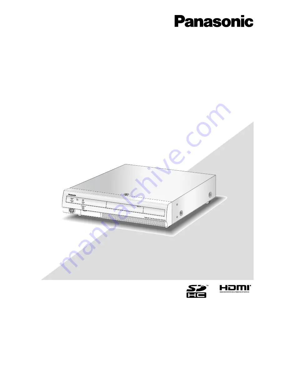
(This illustration represents WJ-NV200VK.)

Installation Guide

Network Disk Recorder


Model No.

 WJ-NV200K, WJ-NV200VK

WJ-NV200K/G

Summary of Contents for WJ-NV200K

Page 1: ... read these instructions carefully and save this manual for future use The model number is abbreviated in some descriptions in this manual This illustration represents WJ NV200VK Installation Guide Network Disk Recorder Model No WJ NV200K WJ NV200VK WJ NV200K G ...

Page 2: ...rvice personnel or system installers For PERMANENTLY CONNECTED APPARATUS provided nei ther with an all pole MAINS SWITCH nor an all all pole circuit breaker the installation shall be carried out in accordance with all applicable installation rules The connections should comply with local electrical code This Class A digital apparatus complies with Canadian ICES 003 For Canada The model number and ...

Page 3: ...i direktivene 2006 95 EC og 2004 108 EC Vi deklarerar härmed vårt fulla ansvar för att den produkt till vilken denna deklaration hänvisar är i överensstämmelse med de standarder eller andra normativa dokument som framställs i direktiv nr 2006 95 EC och 2004 108 EC Ilmoitamme yksinomaisella vastuullamme että tuote jota tämä ilmoitus koskee noudattaa seuraavia standardeja tai muita ohjeellisia asiak...

Page 4: ...T OR INDIRECT SPECIAL CONSEQUENTIAL OR EXEMPLARY ARISING OUT OF OR RELATING TO THE PRODUCT 2 PERSONAL INJURY OR ANY DAMAGE CAUSED BY INAPPROPRIATE USE OR NEGLIGENT OPERATION OF THE USER 3 UNAUTHORIZED DISASSEMBLE REPAIR OR MODIFICATION OF THE PRODUCT BY THE USER 4 INCONVENIENCE OR ANY LOSS ARISING WHEN IMAGES ARE NOT DISPLAYED DUE TO ANY REASON OR CAUSE INCLUDING ANY FAILURE OR PROBLEM OF THE PROD...

Page 5: ... your outlet consult an electrician for replacement of the obsolete outlet 10 Protect the power cord from being walked on or pinched particularly at plugs convenience receptacles and the point where they exit from the apparatus 11 Only use attachments accessories specified by the manufacturer 12 Use only with the cart stand tripod bracket or table specified by the manufacturer or sold with the app...

Page 6: ...monitor Main monitor 62 Set up the live monitor Live monitor 62 Configure other settings relating to monitors Advanced setup 63 Configure the settings relating to network Network 65 Configure the basic network settings Basic 65 Configure the settings relating to the mail notification e Mail 68 Configure the Panasonic alarm protocol settings Panasonic alarm protocol 69 Configure the settings relati...

Page 7: ...080 can be saved as video data Live images from up to 16 cameras with the image capture size of SXVGA 1280 x 960 can be displayed simultaneously In addition this recorder supports the H 264 video compression format that can achieve recording at a high frame rate for a long time This recorder also supports the Full HD output HDMI that can display recorded images and live images from the cameras in ...

Page 8: ...8 System configuration PC Main monitor Live monitor Powered speaker Network camera x 16 max Network This illustration represents WJ NV200VK ...

Page 9: ... the dedicated software option that receives and displays the event and error information compatible cameras and their versions System requirements for a PC It is recommended to operate this product using a PC that meets the following system requirements OS Microsoft Windows 7 Microsoft Windows Vista Web browser Windows Internet Explorer 9 0 32 bit Windows Internet Explorer 8 0 32 bit Windows Inte...

Page 10: ...is described as Windows 7 Microsoft Windows Vista Business SP1 32 bit is described as Windows Vista Windows Internet Explorer 9 0 Windows Internet Explorer 8 0 and Windows Internet Explorer 7 0 are described as Internet Explorer SDHC SD memory card is described as SD card or SD memory card Network cameras are described as cameras Copyright Except for open source software licensed under GPL LGPL an...

Page 11: ...irewall etc If this product is connected to a network that includes PCs make sure that the system is not infected by computer viruses or other malicious entities using a regularly updated anti virus program anti spyware program etc Protect your network against unauthorized access by restricting users to those who log in with an authorized user name and password After the product is accessed by the...

Page 12: ...nder these setting conditions are played back on the recorder It is impossible to register face images displayed on images from the camera while recording is not being performed It is recommended to perform settings to record images for 24 hours The face matching function is unavailable while recorded images are being played back or while the setup menu is being dis played While the face matching ...

Page 13: ...cted camera for further information Compression H 264 Image capture size 1280 960 Frame rate 5 ips Max bit rate per client 4096 kbps as indication Refresh interval 1 s Super Dynamic SD Off Adaptive black stretch Off Back light compensation BLC Off Shutter speed Light control mode 1 250 fix AGC On High Black white mode Off DNR Low Face detection On By masking an area with remarkable luminance chang...

Page 14: ...ght sources such as the headlights of a car rising sunlight or setting sunlight may affect the shooting place from outside To improve the performance of face matching Register the target face images from the images recorded by the camera installed under the same conditions Perform settings for the camera so that the camera can shoot face images at a balanced illuminance level both in the day time ...

Page 15: ...are vulnerable to vibration Handle them with care It is possible to damage them if they are moved while their motors are still running Do not move or install this product just after turning the power on or off for around 30 seconds The hard disk drives are running The lifetime of hard disk drives is limited by use Write errors may occur frequently after around 20 000 hours of operation and the hea...

Page 16: ... this product has detected the internal error and reboot becomes necessary About DVD disks DVD drive equipped models only It is impossible to use commercially released or rental DVD disks When the data were copied from this prod uct it is impossible to play back DVD disks on other DVD drives or players Do not leave the disk tray open Do not mount anything other than specified disks on the disk tra...

Page 17: ...ing fans Clear a space of more than 5 cm 2 inches from both sides the top and the rear of the product Do not block the ventilation openings on the front side since this prod uct is designed to cool the hard disk drives by inhaling air from the front Avoid placing this product near noise sources If the cables are placed near noise sources such as fluores cent lamps noises may be produced In this ca...

Page 18: ...s PDF is clicked w Buzzer stop button BUZZER STOP Press this button to stop the buzzer that started sound ing at an alarm error occurrence Refer to the operating instructions PDF for further information about alarms and errors e DVD drive Recorded images can be saved on a DVD disc com mercially available Page 19 r Mouse connection port MOUSE The provided mouse is connected to this port t Restart b...

Page 19: ... down SDHC SD memory card slot cover When inserting an SD memory card confirm that the label on the SD memory card is upside and only the upper right corner of the card has different shape Insert a DVD disc commercially available only for WJ NV200VK Step 1 Open the DVD drive cover Pull the tab down DVD drive cover Step 2 After confirming that the power of the recorder is on press the eject button ...

Page 20: ...ush the tray to the end Click sound will be heard and the tray will be fixed Step 5 Close the DVD drive cover Important When opening closing the DVD drive tray do not apply force on the tray When not using the DVD drive close the disc tray When removing the disc from the tray hold the spindle to detach the disc If trying to detach the disc forcibly it can damage both the disc and the DVD drive Spi...

Page 21: ...mages or recorded images is output Connect such device as a powered speaker 1 Monitor output connector HDMI AV OUT This connector is used to connect to an HDMI ready monitor the main monitor 2 HDD slots HDD1 HDD2 Hard disk drives locally procured can be installed into these slots Contact your dealer for installing replacing the hard disk drives 3 SIGNAL GND terminal SIGNAL GND Connect this termina...

Page 22: ...g from 0 Highest to 4 Low Administrator 0 Highest Manager 1 High Operator 2 Viewer 3 Logged out 4 Low When the two or more users at the same level perform the same operation the recorder will be con trolled in accordance with the latest operation Default screen Select a startup screen to be displayed on the main monitor or a PC screen after login from the follow ing When operating from a PC via a ...

Page 23: ...wer of the recorder v If necessary register the Registration Key for the recorder and that for the Additional Business Intelligence Kit Important Be sure to register the Registration Key of the recorder b Register the date time and cameras on Easy Start When it is not necessary to change other default set tings it is possible to start operations After cameras are added or replaced register the cam...

Page 24: ... via a switching hub Use a LAN cable straight to connect the recorder and the switching hub Recorder Network camera x 16 max LAN cable locally procured 10BASE T 100BASE X 1000BASE T category 5e or better straight for WJ NV200K WJ NV200VK category 7 straight for WJ NV200K G Switching hub ...

Page 25: ... locally procured Note Use High Speed HDMI Cable To maintain the stable performance without deteriorating the image quality use an HDMI cable whose length is 10 m 32 81 feet or less When an HDMI cable is used it is possible to output audio from the connected monitor Live monitor Powered speaker Audio cable locally procured HDMI cable option BNC cable locally procured Recorder Main monitor When out...

Page 26: ... 0 IP address 192 168 0 x except 0 1 250 and 255 Subnet mask 255 255 255 0 Default gateway 192 168 0 1 PC Recorder IP address 192 168 0 250 Subnet mask 255 255 255 0 Default gateway 192 168 0 1 LAN cable locally procured 10BASE T 100BASE TX 1000BASE T category 5e or better straight for WJ NV200K WJ NV200VK category 7 straight for WJ NV200K G ...

Page 27: ... 24 V DC max 100 mA 11 Alarm reset input Canceling the alarm display Non voltage make contact 5 V pull up 100 mA 12 N A 13 Signal ground 14 Signal ground 15 Face matching output Signal output at the occurrence of a face match ing alarm Open collector output 24 V DC max 100 mA 16 HDD error output Signal output upon detection of an HDD error 17 Camera error output Signal output upon detection of a c...

Page 28: ...tment signal input select On for Auto time adjustment Page 43 Connection of the control output When an alarm device such as a buzzer or a lamp is connected the signal output from pin no 10 and pin nos 15 19 can be used to notify the status by sounding a buzzer or lighting a lamp The connection example of the HDD error output pin no 16 is as follows 13 20 Signal ground Sensor signal input Alarm inp...

Page 29: ...d L active Camera error output At an error occurrence until the period selected for Error output duration has passed or the camera reset L active Recorder error output At an error occurrence until the period selected for Error output duration has passed L active Recording error output At an error occurrence until the period selected for Error output duration has passed L active Time adjustment sig...

Page 30: ...onnectors to prevent the hard disk drive from damaging by static electricity Contact your dealer for hard disk drives that works on the recorder Please be forewarned that operation with any hard disk drive other than the specified models is not guaranteed under any circumstances When using multiple hard disk drives use the same model If different models are used together even when the capacities o...

Page 31: ...ep 4 of Install the hard disk drives page 31 Step 6 Turn on the power of the recorder Page 32 New hard disk drive will be formatted automatically When the formatting is completed the hard disk drive will become operable When the hard disk drive is formerly used for recording perform the link process page 81 on the HDD man agement page The status of hard disk drive can be checked on the setup menu ...

Page 32: ...he startup window will be displayed on the main monitor Important Never turn off the power of the recorder during startup Note If the license for the recorder has not been registered yet the message asking you to register the Registration Key will be displayed Step 2 If the Registration Key for the recorder has not been regis tered yet register the Registration Key by following the procedures on p...

Page 33: ...ming that the HDD1 and HDD2 indicators are off The OPERATE indicator will go off Note Be sure to perform the operation to start recording select On for Recording mode after turning on the power of the recorder again During playback Step 1 Stop playback Operating Instructions PDF Step 2 Unplug the power plug from the outlet after confirming that the HDD1 and HDD2 indicators are off The OPERATE indi...

Page 34: ... will not be effective before the recorder is rebooted Register the license Registration Key Step 1 Obtain the Registration Key for the recorder by following the instructions on the provided Activation Key Card When using the extra functions obtain the Registration Key for Additional Business Intelligence Kit WJ NVF20 option or WJ NVF20E option Refer to the Activation Key Card for further informat...

Page 35: ...tra functions enter the Registration Key for the Additional Business Intelligence Kit obtained in Step 1 on Additional business intelligence Registration Key of the registration window in Step 5 The operations are the same as those of Step 6 and 7 Note Register the license for the recorder before registering that for the Additional Business Intelligence Kit They cannot be registered in the reverse...

Page 36: ...ield has the D and C buttons or the C button the setting value can be changed using the mouse wheel When no operation is made for 10 seconds or more the mouse cursor will be hidden The mouse cursor will be dis played when the mouse is moved The recorder can be operated using the provided mouse connected to the mouse connection port on the front side of the recorder It is also possible to perform o...

Page 37: ...the cursor in the entry field A a button This button changes the characters to be entered between capital letters and small letters Next button Changes the keys to be displayed for character entry The displayed keys are changed as follows Keys for the language selected by the language selec tion pull down menu Combination characters Special characters Enter button Determines the entered characters...

Page 38: ...the setup pages e Easy Start button It is possible to configure the minimum settings required to operate the recorder such as date time and camera registration r Basic setup Setup page buttons Each Basic setup page will be displayed t Advanced setup button The buttons to open the corresponding setup pages of the Advanced setup menu will be displayed When clicking this button again the buttons will...

Page 39: ... to Detect cameras for registration Detect cam eras page 46 instead of this section The minimum settings required to operate the recorder such as the date time camera registration recording can be config ured on the setup menu the Quick setup menu Easy Start First configure the minimum settings on Easy Start and to configure more advanced settings go to each setup page Available settings on Easy S...

Page 40: ...btains the latest image from the camera that has been replaced Exit button Exits the setup menu and returns to the top screen of the setup menu Note Before the settings register the cameras into the net work New button Detects all the connected cameras The models and results of the detected cameras will be dis played Make sure that the model numbers of all the con nected cameras are being displaye...

Page 41: ...days Calculates and displays the total number of days for which recording on the hard disk drives is available Note The referenced recording days will be calculated based on the assumption that recording is started on Monday When the HDD saving mode is set the actual recording days are longer than the referenced recording days Page 52 The HDD consumption for the event recording will be excluded If...

Page 42: ... settings such as date time and daylight saving time Camera button Displays the Camera page Perform registration and setup of network cameras REC event button Displays the REC event page Set up the recording schedules cameras and the face matching function Set up date time and language Date Language The Date Language page has the Date time adjustment Date time settings and Language tabs Date time ...

Page 43: ...es the hour the time will be adjusted to 00 minutes 00 seconds Default Off Date time settings tab Perform settings such as date time format time zone daylight saving time and time adjustment method Display format Select a display format for the current date time Note Date time display on the Camera setup tab page 49 corresponds to the display format settings on this tab Date Select a date time dis...

Page 44: ...44 Language tab Select the display language for the main monitor and for the web browser on the PC Language 日本語 English Français Español Deutsch Italiano Русский Default English ...

Page 45: ... infor mation window opens to edit the settings Page 47 In the event of communication trouble with the camera one of the following error messages is displayed for Error infor mation Connection error The communication with the camera disconnected Authentication error The user authentication of the cam era failed Camera error The response from the camera is incor rect Note When an error message is d...

Page 46: ... to Easy Start page 39 for further information Results Refer to Easy Start page 39 for further information IP address Displays the IP addresses configured for the detected cam eras Auto addressing The IP addresses of the cameras whose checkboxes are marked will be automatically configured Note It is impossible to register the cameras in other subnets via the same router For the security enhancemen...

Page 47: ...for Compression the live image transmission rate and the frame rate will be changed automatically to 5 ips Page 52 When selecting MPEG 4 for Compression the image size will be changed automatically to VGA Page 53 When selecting H 264 for Compression it will become possible to select XF for the image quality set ting Depending on the model of the camera the camera may reboot when the compression me...

Page 48: ...rrent settings using this recorder Interchange camera numbers Change the display position of camera Click the Setup button for Change the display position of camera on the Camera registration tab to display the following items The registered cameras will be displayed on the screen in the order of 1 2 16 from top left to right To interchange camera numbers drag the camera image to be moved with the...

Page 49: ...y the date time edited on Date time dis play Camera selection Select the camera to which the date time display setting is to be sent Mark the checkbox of the camera to which the setup information is to be transmitted Transmission button Transmit the date time setting to the camera Once transmission is completed and the setting has been applied to the camera OK will be displayed in the Results fiel...

Page 50: ...splay If used in a network environment where frequent errors occur shorten the refresh interval to reduce image distortions However the refresh interval may be longer than the set value 0 2 s 0 5 s 1 s 2 s 3 s Default 1 s Important Image transmission from the camera will temporarily be canceled and no image will be recorded during this period if the set ting to change the refresh interval is trans...

Page 51: ...camera installation Upside down Select the method of camera installation for each camera and transmit the information to the cameras to change the camera set tings Clicking the Setup button for Upside down on the Camera setup tab will display the setup window Upside down On desktop Select this when the camera is to be installed with the dome side up Off ceiling Select this when the camera is to be...

Page 52: ...table Advanced button The Advanced schedule setup page will be displayed In addition to 3 schedule recordings 3 event recordings can be set up Page 53 Recording setup All cameras Set the recording frame rate and image quality The settings will be applied to all cameras Frame rate Select the recording frame rate 1 ips 3 ips 5 ips 10 ips 15 ips 30 ips Default 10 ips Important When selecting MPEG 4 a...

Page 53: ...an alarm occurs 0 s 5 s 10 s 15 s Default 0 s Note The actual recording time may sometimes be longer than the duration selected for this setting Pre event recording is not performed when 0 s is selected When images are set to be recorded together with audio the audio may not be recorded at the beginning of the pre event recording The pre event recording duration of cameras with the image capture s...

Page 54: ...t the configured rate Depending on the model of the camera the camera may reboot when the image capture size is changed The reboot will be detected as a communication error but that is not a malfunction Important The available image capture sizes may differ depending on the model of the camera and the compression meth od Rate Frame rate Page 52 Quality Image quality Page 52 Audio Select whether or...

Page 55: ...ally reset Refer to the operating instructions PDF for further infor mation about alarm reset Default Ext Note If the time set for Output duration or Buzzer duration is longer than that set for Auto reset time the time set for Auto reset time will be applied Message display Select whether or not to display a message on a PC con nected to a network when an alarm occurs On Display a message Off Does...

Page 56: ...ras for recording Default Camera number associated with the terminal num ber Note When many cameras are registered and All is selected for Recording camera the start of alarm recording may be delayed depending on the cameras It is recommend ed to perform pre event recording Preset Select the camera preset position 001 to 256 to which the camera is to be moved when an alarm signal is received If is...

Page 57: ...on Click the button after completing the settings The screen returns to the Event setup tab Set up command alarm Advanced command alarm setup Set up the action to be taken when a command alarm signal received from a PC that is connected via a network protocol trig gers command alarm Refer to Advanced terminal alarm setup to set Mode Recording camera Preset and Terminal output in Setup by cam era p...

Page 58: ... 264 Image capture size SXVGA 1280 960 Frame rate 5 ips Image quality SF HDD saving mode Except When Alarm action is selected for Mode of Advanced face matching alarm setup the sequential display on the live monitor stops To activate the face matching function start face match ing actions Operating Instructions PDF Setup by camera Face matching can be triggered only by Camera 1 fixed To use the fa...

Page 59: ...ing function Off Does not activate the face matching function Default Off Auto image scan button Automatically searches for images suitable for face matching for around 3 seconds before and after the face image is registered For details refer to Auto image scan in Automatically search for face images Auto image scan page 60 Delete To delete images mark their checkboxes Update button Use this butto...

Page 60: ...acceptable for registration double click the face frame The screen returns to the face image registration win dow and the selected face image will be displayed in the face image display area Note When returning to the face image registration window without applying the face image click the Back button Step 5 If necessary configure the setting for face matching actions open the on screen keyboard p...

Page 61: ...the grid divided in 16 x 16 segments It may be possible that the actual matching areas will not be exactly the same as the points designated by clicking the top left corner and bot tom right corner Step 4 To complete the settings click the Back button The screen returns to the face image registration win dow Configure the advanced settings for recording and events Advanced setup Configure the spec...

Page 62: ...itor by selecting the camera images to display the image display duration etc Live sequence Set the display sequence for camera images image switch ing Duration Set the interval duration for switching camera images 5 s 10 s 15 s 30 s Ext Switches Camera 1 to 9 to display images accord ing to the signal input triggered by the terminal alarms from Terminal 1 to 9 Default 10 s Note The terminal statu...

Page 63: ...is actually turned off Off After 15 mins After 30 mins After 1 hour After 3 hours Default Off Backlight will not be turned off The brightness and the backlight will be reset by any mouse operation or operation of the buttons on the recorder s front panel operations on the web browser of the PC will not reset the function The function can also be reset as follows Marking the checkbox for Recover th...

Page 64: ...e image display area on the control screen When the images are enlarged with this setting camera con trol or VMD search may sometimes not work properly in accordance with the specified coordinates or areas Display images in 16 9 aspect ratio on the web brows er window Mark the checkbox to display the images in the web brows er window with the aspect ratio of 16 9 ...

Page 65: ...eway in accordance with the recorder s network environment Enter in the same way as the IP address Default 192 168 0 1 Line speed Specify the line speed for data transmission Auto Line speed will be applied automatically 100M Full 100 Mbps full duplex 100M Half 100 Mbps half duplex 10M Full 10 Mbps full duplex 10M Half 10 Mbps half duplex Default Auto Important When the setup menu is closed after ...

Page 66: ... for the Viewnetcam com service Step 1 Access the URL displayed on Your account link from the PC connected to the Internet The registration window for Viewnetcam com will be displayed Step 2 Register the information for Viewnetcam com by following the instructions of the wizard When the registration window is not displayed check that the PC is being connected to the Internet and click the reload b...

Page 67: ...stra tor of each network The following numbers and the FTP port number are unavailable for the HTTP port number 20 21 23 25 42 53 67 68 69 79 105 110 123 161 162 546 547 995 10001 10002 10003 10004 10005 10006 10007 FTP port number Designate the FTP port number of the recorder It is unnecessary to change it for normal use 1 65535 Default 21 Note The following numbers and the HTTP port number are u...

Page 68: ...he authentication method to send e mails from the following None POP before SMTP SMTP Default None Authentic method User name Enter the user name to be required for the authentication Enter up to 32 alphanumeric characters excluding listed in the description of Note Authentic method Password Enter the password to be required together with the user name for the authentication Enter up to 32 alphanu...

Page 69: ...s It is usually not necessary change the default Default 1818 Retry Set the number of retry attempts for the transmission to the PC 0 8 times In steps of times Default 2 Note If the transmission to the PC fails increase the number of retry attempts Destination address Address1 Address8 Enter the addresses of the recipient PCs Enter the IP address or host name for Address1 Address8 The host name is...

Page 70: ...o 255 alphanumeric characters including hyphens and periods Important It is possible to run the recorder as an NTP server to be referred by the cameras In this case set the port num ber of the camera to 123 Refer to the operating instructions of the connected camera for information on how to configure the settings of the camera SNMP setup Set this item to check the status of the recorder by connec...

Page 71: ...cted for Auto login the user will not be logged out automatically even if other values than Off is selected for Auto logout To prevent inappropriate operations it is recommended to select settings other than Off for Auto logout Network Determine whether or not to require user authentication for operating the recorder from a PC User authentication Select On or Off to determine whether or not to aut...

Page 72: ...be canceled Setup Setup menus can be displayed and the settings can be configured Camera image display The image and audio data of all cameras can be displayed output To set up the display of camera images click the Setup button Set up the user level for individual cameras It is recommended to restrict Setup to the administrator Set up the user level for individual cameras Select the cameras allow...

Page 73: ...ager Operator Viewer Administrator and manager both have the same level but the administrator has the higher priority Default Operator Default screen Select a startup screen to be displayed after login from the following Cam 1 Cam 16 Displays an image from the selected camera channel on a 1 screen 4Screen A 4Screen B 4Screen C 4Screen D 16Screen Refer to the Operating Instructions PDF for further ...

Page 74: ...rs for the password The registered password will be displayed as regardless of what is entered Default 12345 Important For enhanced security make sure to change the admin istrator name and password from the default Change the password on a regular basis Password Retype Enter the password that has been set for Password again for confirmation Level Display the operation level of an administrator It ...

Page 75: ... HDD information will not be updated while the Maintenance page is being displayed The hard disk drives installed in the HDD1 slot and the HDD2 slot are displayed as HDD1 and HDD2 respec tively Capacity Displays the capacities of the hard disk drives Operation Displays the operating time of the hard disk drives Status Displays the statuses of the hard disk drives Normal Hard disk drives that are o...

Page 76: ... infor mation about the error reset Network link down detection Select On or Off to determine whether or not to detect the network disconnection on the network port of the recorder On Detects the network disconnection Off Does not detect the network disconnection Default Off HDD hour meter warning If the operation time of a hard disk drive reaches a specified level a warning will be performed When...

Page 77: ...corder Refer to the Operating Instructions PDF for how to format a SD memory card Registration of license To use the recorder it is necessary to obtain the Registration Key from the key management system and to register the license Enter the license for the recorder Clicking the Setup button will open the registration win dow to register the license Page 78 Reset all settings Initializes the setti...

Page 78: ...t to the entry field is clicked the registration window to register the license When using the recorder for the first time be sure to register the Registration Key Note After registering the license be sure to click the Restart button The recorder will reboot and each license will become effective Additional business intelligence Registration Key When activating the extra functions enter Registrat...

Page 79: ...DHC SD memory card formatted with a PC or another device it is necessary to format it with this recorder Refer to the Operating Instructions PDF for how to format a SD memory card Step 1 Click the Execute button to display the confirmation win dow to start saving Saving the log data on the SD memory card will be start ed Step 2 Click the Back button when saving is completed ...

Page 80: ...ick the OK button after entering Administrator name and Password of an administrator The operations relating to the hard disk drives such as checking the capacity of each recording area and formatting the drives can be performed on the HDD management page of the setup menu the Advanced setup menu Important All other operations such as recording and playback will stop when the HDD management page i...

Page 81: ...lick the Execute button for Format HDD on the General tab HDD management page The window to format hard disk drives will be displayed Step 2 Check the hard disk drives to format in the Format field and click the Start button When OK is displayed on the Results field click the Back button When Error is displayed format the hard disk drives again About the removal process and the link process of har...

Page 82: ...y card on the Extra function page of the setup menu the Advanced setup menu The Extra function page has the Business intelligence tab Important The Extra function button will be displayed under Advanced setup after registering the license for the product or starting using this product on trial Refer to the operating instructions PDF of the Additional Business Intelligence Kit for further informati...

Page 83: ...ll be dis played Calculated result will be dis played Basic setup Remarks are the setting items configured on Easy Start d are the setting items configured from the web browser Menu Tab Setting item including those of the Advanced setup menu Available range Default Remarks Date time adjustment Date Time 2010 1 1 0 00 2034 12 31 23 59 20nn mm 1 0 00 nn and mm are calculated base on the serial numbe...

Page 84: ...name Text will be entered Blank d Password Text will be entered Blank d Port No Port No 80 d Camera setup Date time display Display check box Checked Not checked Checked Display drop down list Off On On Position check box Checked Not checked Checked Position drop down list L Upper L Lower R Upper R Lower L Upper Camera selection Checked Not checked Registered cameras are checked Display Title Disp...

Page 85: ...15 ips 30 ips 10 ips Image quality XF SF FQ NQ FQ Referenced recording days Calculated result will be dis played Calculated result will be dis played Advanced schedule setup Days to record Mon Tue Sun Time table1 Time table2 Off Time table1 d Event recording Event recording duration 2 s 5 s 10 s 20 s 30 s 1 min 2 min 3 min 5 min 10 min 15 min Manual Ext 30 s d Event recording Pre event duration 0 ...

Page 86: ... When the aspect ratio is 16 9 QVGA 320x180 HVGAW 640x360 HD 1280x720 FHD 1920x1080 VGA 640x480 d Rate 1 ips 3 ips 5 ips 10 ips 15 ips 30 ips 10 ips d Quality XF SF FQ NQ FQ d Audio Off On Off d Recording Off On Anytime On d Saving Depend Except Depend d Referenced recording days Calculated result will be dis played Calculated result will be dis played d Event setup Alarm action Output duration 0 ...

Page 87: ...a1 All area Matching area2 4 Undefined Advanced setup Recording mode Off On On d Alarm disarm duration 2 s 3 s 5 s 10 s 2 s d Panasonic alarm port number Port No 1818 d Advanced setup Menu Tab Setting item including those of the Advanced setup menu Available range Default Remarks Monitor Main monitor Camera title Display Off On On d Position L Upper L Lower R Upper R Lower R Upper d Camera title T...

Page 88: ...speed Auto 100M Full 100M Half 10M Full 10M Half Auto d DNS Setup DNS Off Manual Off d Primary server address IP address 0 0 0 0 d Secondary server address IP address 0 0 0 0 d Domain name Text will be entered localdomain d DDNS Setup DDNS Off Viewnetcam com Dynamic DNS update Off d Access interval Viewnetcam com 10 min 20 min 30 min 40 min 50 min 1 h 1 h d Host name Dynamic DNS Text will be enter...

Page 89: ...egistered user names ADMIN d Quick login Off On Off d Auto logout Off After 1 min After 3 mins After 5 mins After 30 mins Off d Network User authentication Off On On d User level settings Camera operation Checked Not checked Manager Checked Fixed Operator Checked Fixed Viewer Checked Fixed Logged out Checked d Camera control Checked Not checked Manager Checked Fixed Operator Checked Viewer Not che...

Page 90: ...nk d Administrator setup Administrator name Text will be entered ADMIN d Password Text will be entered 12345 d Password Retype Text will be entered 12345 d Level Administrator Administrator d Default screen Cam 1 Cam 16 4Screen A 4Screen B 4Screen C 4Screen D 16Screen 4Screen A d Maintenance System informa tion Software version1 Indication only Indication only d Software version2 Indication only I...

Page 91: ...Load face data from SD card None None Download face data None None d Upload face data None None d Firmware update None None d Other None None Registration Key Entry information of the key man agement system MPR ID None Unique number given to the device Activation Key No None Described on the Activation Key Card Registration ID None Described on the Activation Key Card Registration of license Produ...

Page 92: ...only HDD information Operation Indication only Indication only HDD information Status Indication only Indication only HDD information Add Checked Not checked Checked HDD information Results Indication only Indication only Extra function Business intelli gence Accumulate statistics data Off On Off d People count ing Detection area x 0 1280 y 0 960 Detection area1 All area Detection area2 4 No setti...

Page 93: ...ng HDDx HDD error HDD skip 1 warning HDD skip HDDx HDD write error Write error HDDx HDD read error Read error HDDx Alteration detection Altered Cam cc Altered Cam cc Recorder error Remove auto links per HDD HDD removed HDDx HDD removed HDDx HDD error HDD format error Format error HDDx Format error HDDx HDD error HDD removal error Properly recog nized HDD was removed without proper operations Swap ...

Page 94: ...Network error Other errors for SMTP SMTP OTHER_ERR Network error FTP server transfer complete FTP SVR_FWD_OK Other error for FTP FTP OTHER_ERR Network error Synchronization with the NTP server complete NTP GET_TIME_OK Failed to resolve NTP server address from DNS NTP SVR_ADD_ERR Network error Synchronization with the NTP server failed Time is not synchronized NTP TIME_INVALID Network error Failed ...

Page 95: ...ces on Check whether the power is supplied to the camera and the devices Confirm that the cables are connected correctly and firmly Confirm the cables are firmly connected 24 25 Is the monitor luminance appropriately adjusted or is the contrast appropriately adjusted Check whether the monitor settings are appropriate Users who have logged into the system may not be authorized to display the images...

Page 96: ...cc indi cation is displayed on the main mon itor Confirm that the camera is connected correctly and firmly Check the camera connection 23 If the connection is appropriate the cable may be broken or the camera may be out of order Consult the dealer The Thermal error indication is dis played on the main monitor The ambient operating temperature is 5 C to 45 C 41 F to 113 F The Thermal error indicati...

Page 97: ...ork subnet to be accessed When the recorder and the client PC are on the same subnet is the same subnet set for the IP addresses of the recorder and the PC Or is Use Proxy Server for the settings of the browser checked When accessing the recorder in the same subnet entering the address of the recorder in the Don t Use Proxy For These Addresses box is recommended 65 When displaying images on a mult...

Page 98: ...ord insulation is dam aged The power cord connector or power plug is damaged This may result in electric shock or a fire Unplug the power plug from the AC outlet immediately and refer to qualified service per sonnel The power cord plug and connec tors get hot during use The power cord gets hot when bent or stretched ...

Page 99: ... disk drive 3 5 type Serial ATA hard disk drive Up to 2 hard disk drives can be installed DVD Only for WJ NV200VK Supported DVD disk type DVD R R Not supported DVD R DL R DL DVD R for authoring 8 cm disks Input Output Video Spot output connector 1 V p p 75 Ω x1 BNC Monitor HDMI connector HDMI x1 Audio Audio output connector 10 dBv 600 Ω unbalanced x1 RCA pin jack Others Mouse connection port x1 Al...

Page 100: ...anty provided with WJ NV200K WJ NV200VK 1 pc The following are for installation Power cord WJ NV200K WJ NV200VK 1 pc Power cord WJ NV200K G 2 pcs HDD fixing screw WJ NV200K WJ NV200K G 8 pcs HDD fixing screw WJ NV200VK 4 pcs The CD ROM contains the operating instructions PDFs Standard accessories ...

Page 101: ...101 ...

Page 102: ... supplier for further information Information on Disposal in other Countries outside the European Union These symbols are only valid in the European Union If you wish to discard these items please contact your local authorities or dealer and ask for the correct method of disposal Note for the battery symbol bottom two symbol examples This symbol might be used in combination with a chemical symbol ...

Reviews: