iZ Technology RADAR 24, Operation Manual
For the iZ Technology RADAR 24, you can easily access the comprehensive Operation Manual via our website, completely free of charge. Download this essential manual to fully understand and maximize the potential of this exceptional product. Visit manualshive.com to grab your copy and unlock the full power of the RADAR 24.
Share
Download


Reviews:
No comments
Related manuals for RADAR 24
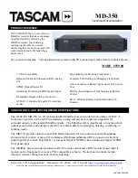
MD-350
Brand: Tascam Pages: 2
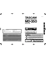
MD-350
Brand: Tascam Pages: 56

VN-7600PC
Brand: Olympus Pages: 12

DDR-5300
Brand: Diasonic Pages: 30

DDR-5100
Brand: Diasonic Pages: 43

MD-185X
Brand: Onkyo Pages: 36

MD-105X
Brand: Onkyo Pages: 56

195374
Brand: Miller Electric Pages: 52

DTH 7000 E
Brand: THOMSON Pages: 60

CB1160HDD
Brand: THOMSON Pages: 84

OMEGA 890-0032-000
Brand: 3M Pages: 112

MD 80137
Brand: Medion Pages: 53

MD 84000
Brand: Medion Pages: 186

DS-3500
Brand: Olympus Pages: 14

DVDR1000/001
Brand: Philips Pages: 317

DVDR 615/17
Brand: Philips Pages: 192

DVDR 725H/00
Brand: Philips Pages: 116

DVDR3330H/02
Brand: Philips Pages: 3


