


Before attempting to connect or operate this product,
please read these instructions carefully and save this manual for future use.
Model No.
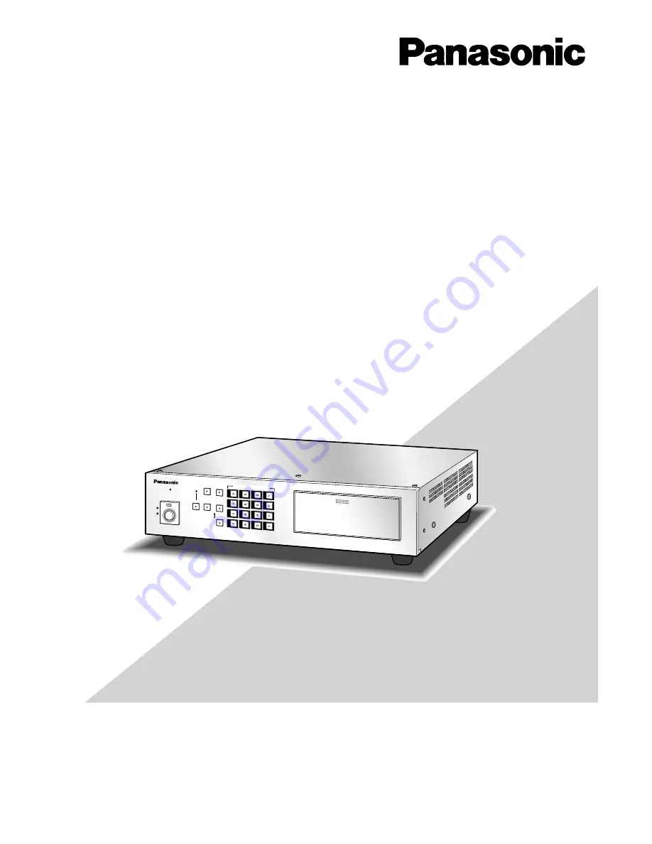
WJ-FS616C
Video Multiplexer
Operating Instructions
LOCK
MULTI
SCREEN
MULTI SCREEN
SELECT
SEQUENCET
ALARM
RESET
SPOT
VCR
CAM
POWER
ON
OFF
1
2
3
4
5
6
7
8
9
10
11
12
16
15
14
13
CAMERA/PRE SET POSITION
PUSH OPEN
Digital Video
Multiplexer WJ-FS
616
C
Summary of Contents for WJ-FS616C
Page 23: ...23 SETUP PROCEDURES ...
Page 47: ...47 OPERATING PROCEDURES ...


