background image

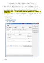
© Panasonic Corporation 2009. Unauthorized copy-
ing and distribution is a violation of law.

ORDER NO. VM0902017CE

B27

SD Video Camera

Model No.

SDR-SW21P

       SDR-SW21PC
       SDR-SW21PU
       SDR-SW21EB
       SDR-SW21EC
       SDR-SW21EE
       SDR-SW21EF
       SDR-SW21EG
       SDR-SW21EP
       SDR-SW21GC
       SDR-SW21GK
       SDR-SW21GN

Vol. 1

Colour
(S)...........Silver Type (except EC/EF)
(D)...........Orange Type (except EF/GK)
(G)...........Green Type (except EE/GK)

Summary of Contents for SDR-SW21PC

Page 1: ...of law ORDER NO VM0902017CE B27 SD Video Camera Model No SDR SW21P SDR SW21PC SDR SW21PU SDR SW21EB SDR SW21EC SDR SW21EE SDR SW21EF SDR SW21EG SDR SW21EP SDR SW21GC SDR SW21GK SDR SW21GN Vol 1 Colou...

Page 2: ...l 8 4 Specifications 9 5 Location of Controls and Components 11 6 Service Mode 12 6 1 Lock Search History Indication 13 7 Troubleshooting Guide 14 7 1 Confirmation Flow of Waterproof 14 7 2 Airtight I...

Page 3: ...exposed to shock hazards 1 2 Leakage Current Cold Check 1 Unplug the AC cord and connect a jumper between the two prongs on the plug 2 Measure the resistance value with an ohmmeter between the jumper...

Page 4: ...y a grounded tip soldering iron to solder or unsolder ES devices 4 Use only an antistatic solder removal device Some solder removal devices not classified as antistatic ESD protected can generate elec...

Page 5: ...ust not be used until a replacement cover is obtained A replacement fuse cover can be purchased from your local Panasonic Dealer If the fitted moulded plug is unsuitable for the socket outlet in your...

Page 6: ...er be subjected to excessive heat or discharge It must therefore only be fitted in requirement designed specifically for its use Replacement batteries must be of same type and manufacture They must be...

Page 7: ...Remove the remaining lead free solder on the PCB cleanly for soldering of the new IC Since the melting point of the lead free solder is higher than that of the normal lead solder it takes the longer t...

Page 8: ...t the INITIAL SETTING data which is stored in Flash ROM mounted on Main PCB 3 4 1 Defining methods To define the model suffix to be serviced refer to the rating label which is putted on the Unit NOTE...

Page 9: ...9 4 Specifications For NTSC areas For PAL areas...

Page 10: ...10...

Page 11: ...attery door Tripod mounting hole For tripod sold separately mounting instructions see the user s guide for the tripod With some tripods the card battery door cannot be opened when the unit is mounted...

Page 12: ...e than 3 seconds until the top screen of the Service Mode Menu being displayed Service mode menu NOTE Do not using service mode except 4 of Service Mode Menu 3 End method of the top screen of the serv...

Page 13: ...d 3 Select 4 Lock search history indication Operation specifications Indication contents Lock search history indication Display the camera system error cord for three histories saved in EEPROM The err...

Page 14: ...14 7 Troubleshooting Guide 7 1 Confirmation Flow of Waterproof...

Page 15: ...15 7 2 Airtight Inspection with Air Leak Tester...

Page 16: ...16 7 3 Air Leak Tester RFKZ0528 Operating Instruction...

Page 17: ...17...

Page 18: ...18...

Page 19: ...19...

Page 20: ...n PCB After replacing the MAIN PCB be sure to achieve adjustment The adjustment instruction is available at software download on the Support Information from NWBG VDBG AVC web site in TSN system toget...

Page 21: ...ts No Connection Form 1 VFK1364 FP6931 MAIN CCD UNIT 14PIN 0 5 FFC 2 VFK1461 FP6971 MAIN LENS UNIT 20PIN 0 5 FFC 3 VFK1388 FP6902 MAIN FP4802 FRONT 12PIN 0 5 FFC 4 VFK1716 FP6903 MAIN FP8101 MONITOR 2...

Page 22: ...22 9 Disassembly and Assembly Instructions 9 1 Disassembly Flow Chart 9 2 PCB Location...

Page 23: ...2 Ribs FP4801 Flex Front P C B 15 LCD unit Fig D18 R base rubber 1 Screw O Fig D19 3 Screws P GND O ring LCD unit 16 LCD hinge unit Monitor P C B Fig D20 4 Screws Q Packing angle 4 Screw O rings 2 Sc...

Page 24: ...24 9 3 1 Removal of the Tripod piece and Access panel light Fig D1 Fig D2 9 3 2 Removal of the Front case Fig D3...

Page 25: ...25 9 3 3 Removal of the Rear cover Fig D4 9 3 4 Removal of the R cover Fig D5 Fig D6 9 3 5 Removal of the Top cover Fig D7...

Page 26: ...26 9 3 6 Removal of the Lens piece Lens protection glass and Lens damper Fig D8 9 3 7 Removal of the Side case L unit Fig D9...

Page 27: ...27 Fig D10 9 3 8 Removal of the Lens unit Main P C B Fig D11...

Page 28: ...28 9 3 9 Removal of the Radiation plate Fig D12 9 3 10 Removal of the Battery catcher unit Fig D13 9 3 11 Removal of the Main P C B and Jack P C B Fig D14...

Page 29: ...29 9 3 12 Removal of the Lens unit Fig D15 9 3 13 Removal of the Battery case Fig D16 9 3 14 Removal of the Front P C B Fig D17 9 3 15 Removal of the LCD unit Fig D18...

Page 30: ...30 Fig D19 9 3 16 Removal of the LCD hinge unit and Monitor P C B Fig D20...

Page 31: ...31 Fig D21 9 3 17 Removal of the LCD panel Fig D22...

Page 32: ...32 Fig D23 9 3 18 Removal of the Speaker unit and Operation FPC unit Fig D24...

Page 33: ...33 Fig D25 Fig D26...

Page 34: ...34 9 3 19 Removal of the CCD unit and Optical filter Fig D27 9 3 20 Removal of the IRIS unit Fig D28 Fig D29 9 3 21 Removal of the Zoom motor unit Fig D30...

Page 35: ...emoval of the Focus motor unit Fig D31 9 3 23 Removal of the Master flange 4th moving frame unit and 3rd moving frame unit Fig D32 9 3 24 Removal of the Guide pole S Guide pole and 2nd moving frame un...

Page 36: ...method of the main unit and an exclusive adjustment jig as follows 10 1 1 Adjustment Procedure Connect the main unit to PC with USB The adjustment instruction is available at Software download on the...

Page 37: ...on is available at Software download on the Support Information from NWBG VDBG AVC web site in TSN System 10 2 Repair Record Using the applicable items in Repair Maintenance that is newly provided in...

Page 38: ...38 11 Maintenace 11 1 Regular Maintenance Flow...

Page 39: ...39 11 2 Component Kits of Waterproof...

Page 40: ...completed 5 Set the mode dial to the OFF position to close the Factory Setting 12 2 WHAT IS THE FACTORY SETTINGS The factory settings clean up and or refresh the following settings 1 The OSD MENU sett...

Page 41: ...SDR SW21EF SDR SW21EG SDR SW21EP SDR SW21GC SDR SW21GK SDR SW21GN SDR SW21P SDR SW21PC SDR SW21PU SD Video Camera Name of Signal OFTR FEP This signal is connected to the FEP schematic diagram Circuit...

Page 42: ...ER ON IC4801 1 3 2 IC4801 2 3 2 IC4801 3 3 2 IC4801 4 0 IC4801 5 3 2 IC4801 6 3 2 IC4801 7 3 2 IC4801 8 6 2 Q4801 E 5 4 Q4801 C 6 2 Q4801 B 6 1 Q6501 E 2 7 Q6501 C 3 7 Q6501 B 0 7 Q6502 E 3 4 Q6502 C...

Page 43: ...3 VERTICAL DRIVER IC302 TG AFE IC3400 MPEG CODEC IC1001 POWER CIRCUIT IC2304 RTC IC6004 EEPROM IC601 LCD CONTROLLER COLOR LCD PANEL 2 7 PANEL IC3401 SDRAM 512Mbit IC3402 FLASH ROM 512Mbit SD CARD USB...

Page 44: ...LCD 8R5V LCD B LCD R LCD G 7 1 2 3 5 6 7 8 4 LCD HST LCD HCK1 LCD PSIG LCD HCK2 LCD RL LCD G LCD PCG LCD R 9 11 10 13 14 12 LCD XSTB LCD WIDE LCD B LCD 8R5V LCD UD LCD EN 15 16 LCD VCK LCD VST 17 LCD...

Page 45: ...2 8 8 8 8 8 8 8 8 8 8 8 8 4 8 8 5 3 3 5 3 5 0 2 0 2 8 8 5 6 29A4 8A 4 29A4 8A 4 29A4 8A 4 29A4 8 29A 66 A 0 A 0 A 0 A 0 A 0 A 0 A 0 A A4 5 0 5 0 55 0 4 8 4 8 4 6 4 8 61 0 66 A A176A A A176A4 61 SDR S...

Page 46: ...75 A A75 A 29A 2A 2A 0 29A 2A A 0 29A 2A A 0 29A 2A 2 2A 4 1 10 4 1 10 2 7 0A 2 7 0A 8 75 8 75 8 75 0 A 0 A 0 A 0 A 0 A 0 A 0 A 0 A 0 A 0 A 0 A 0 5 1 176 5 1 75 8176 4176 7 1A4 8 1A176 7 1A 75 A 6A 2...

Page 47: ...3 5 3 5 29A 4 8A 29A 8 A A A A A4A A A A A A A A 29A 4 8A A A A A4 A A 4 A A 8 A A 8 A 106 A 1 A 0 A 0 A 0 A8 A 0 A856 4 56 049 6 56 855 2 56 4 6 25 6 56 0 90 855 8 049 5 856 8 1 61 510 2 0 A7 A 0 A...

Page 48: ...A 19 9 A 8 8 8 8 6 A 19 8 761A59 29A 27A8 8 6 2 29A46 4 8 8 6 2 219 4 59 7 OO OO A 1 29A 27A8 29A 27A8 5 5A59 0 0 0 0 0 0 6 A 8 A4 2A10 12 0 2A1 15 8 8 8 A2 2A4 8 8 8 8 2A2 219 4A59 4 6 72 8 8 6 55 8...

Page 49: ...S 9 S4 6 CCD FPC Schematic Diagram 4 8 5 3 6 4 4 8 8 8 8 8 8 0 0 0 0 8 8 57 57 8 8 176 6 56 26 8 5 59 8176 61 57 SDR SW21 Series CCD FPC Schematic Diagram 10 9 8 7 6 5 4 3 2 1 G F E D C B A...

Page 50: ...S 10 S5 Print Circuit Board S5 1 Front P C B 4 4 4 4 4 4 3 3 2 2 4 4 4 4 4 4 4 8 8 4 3 4 4 4 SDR SW21 Series Front P C B 10 9 8 7 6 5 4 3 2 1 G F E D C B A Foil Side Component Side...

Page 51: ...S 11 S5 2 Jack P C B 8 3 4 4 4 2 8 2 4 4 SDR SW21 Series Jack P C B 10 9 8 7 6 5 4 3 2 1 G F E D C B A Foil Side Component Side...

Page 52: ...S 12 S5 3 Monitor P C B S5 3 1 Monitor P C B Component Side SDR SW21 Series Monitor P C B Component Side 10 9 8 7 6 5 4 3 2 1 G F E D C B A Component Side...

Page 53: ...S 13 S5 3 2 Monitor P C B Foil Side 2 4 3 4 4 4 4 3 3 3 3 3 3 2 2 4 4 4 4 4 4 4 4 4 4 3 4 SDR SW21 Series Monitor P C B Foil Side 10 9 8 7 6 5 4 3 2 1 G F E D C B A Foil Side...

Page 54: ...S 14 S5 4 Operation FPC P C B 4 4 4 4 4 4 4 4 4 4 4 4 4 4 4 4 4 4 4 4 5 6 5 5 5 5 5 5 5 5 5 5 5 5 SDR SW21 Series Operation FPC P C B 10 9 8 7 6 5 4 3 2 1 G F E D C B A Foil Side...

Page 55: ...S 15 S5 5 CCD FPC P C B 6 4 3 SDR SW21 Series CCD FPC P C B 10 9 8 7 6 5 4 3 2 1 G F E D C B A Foil Side Component Side...

Page 56: ...S 16...

Page 57: ...ICE Components identified with the mark have the special characteristics for safety When replacing any of these components use only the same type 3 Unless otherwise specified All resistors are in OHMS...

Page 58: ...CH 1 10W 270 1 C6505 F1G0J224A004 C CAPACITOR CH 6 3V 0 22U 1 R8106 ERJ3RBD271 M RESISTOR CH 1 10W 270 1 R8107 ERJ3RED270 M RESISTOR CH 1 10W 27 1 D6503 MA3S132D0L DIODE 1 E S D R8110 ERJ3RED270 M RES...

Page 59: ...rt No Part Name Description Pcs Remarks Q6351 B1DFDD000019 TRANSISTOR 1 E S D R6351 D1JBR102A006 RESISTOR 1 16W 1K 1 R6352 D1JBR102A006 RESISTOR 1 16W 1K 1 R6353 D1JBR102A006 RESISTOR 1 16W 1K 1 R6354...

Page 60: ...6 SCREW 1 49 VKF4487 L PIECE 1 D B33 VHD1986 SCREW 1 49 VKF4521 L PIECE 1 G B34 VHD1986 SCREW 1 50 VGQ0D39 JACK DOOR PIECE 1 B35 VHD1986 SCREW 1 51 VGQ0D44 BATTERY DOOR PIECE 1 B36 VHD1984 SCREW 1 52...

Page 61: ...NC0005 ZOOM MOTOR UNIT 1 13 VSC5959 LCD SHIELD CASE 1 212 L6HA64NC0006 FOCUS MOTOR UNIT 1 14 L5BDDYH00025 LCD PANEL 1 213 VEK0L06 CCD UNIT 1 EB EC EE EF EG EP 15 VGQ9366 LIGHT GUIDE HOLDER 1 GC GK GN...

Page 62: ...INSTRUCTIONS 1 EF EG FRENCH 310 VQT2A21 OPERATING INSTRUCTIONS 1 EG GERMAN 310 VQT2A23 OPERATING INSTRUCTIONS 1 EG ITALIAN 310 VQT2A24 OPERATING INSTRUCTIONS 1 EG DUTCH 310 VQT2A25 OPERATING INSTRUCT...

Page 63: ...PU 402 VUKM7845 WATORPROOF KIT LCD UNIT 1 D 401 VUYK3E72PC WATORPROOF KIT MAIN UNIT 1 S PC 402 VUKM7892 WATORPROOF KIT LCD UNIT 1 G 401 VUYK3E73GK WATORPROOF KIT MAIN UNIT 1 S GK 401 VUYK2X96EG WATORP...

Page 64: ...B12 B11 B31 B34 57 60 59 B38 B37 B36 66 65 64 39 B25 78 48 47 B23 B22 44 46 45 B53 B54 B55 69 B56 67 68 71 70 B58 72 B27 B26 56 55 B49 B50 B51 B57 B52 54 53 B28 52 41 58 B14 B17 26 43 50 42 B24 B21 51...

Page 65: ...23 B10 B9 9 74 21 20 19 16 17 18 15 14 13 12 3 7 5 B8 B7 B6 B5 4 8 6 11 22 10 S7 2 LCD Section S 25...

Page 66: ...S7 3 Lens Section S 26 B209 B208 211 203 B207 B206 B205 207 210 212 B210 B211 B202 B204 B203 206 209 208 204 201 202 B201 B200 200 205 214 213...

Page 67: ...1 EC EE EF EG EP GC 303 306 305 302 308 315 307 314 311 301 310 321 317 318 304 309 313 312 This PACKING CASE is for the cabinet colour black Please put the colour label matched to the cabinet colour...

Page 68: ...S7 5 Waterproof Kit Main Unit S 28 401 401 401 401 401 401 401 401 401 401 401 401 401 401 401 401 401 401 401 401 401 401 401 401 401 401 401 401 401 401 401 401...

Page 69: ...S7 6 Waterproof Kit LCD Unit S 29 402 402 402 402 402 402 402 402 402 402 402 402 402 402...

Reviews: