

-1-
-3-
-4-
-5-
-2-
-6-
-8-
-9-
-10-
-7-
Red and black
connecting
wires:
These are the
power con-
nections of the
camera.
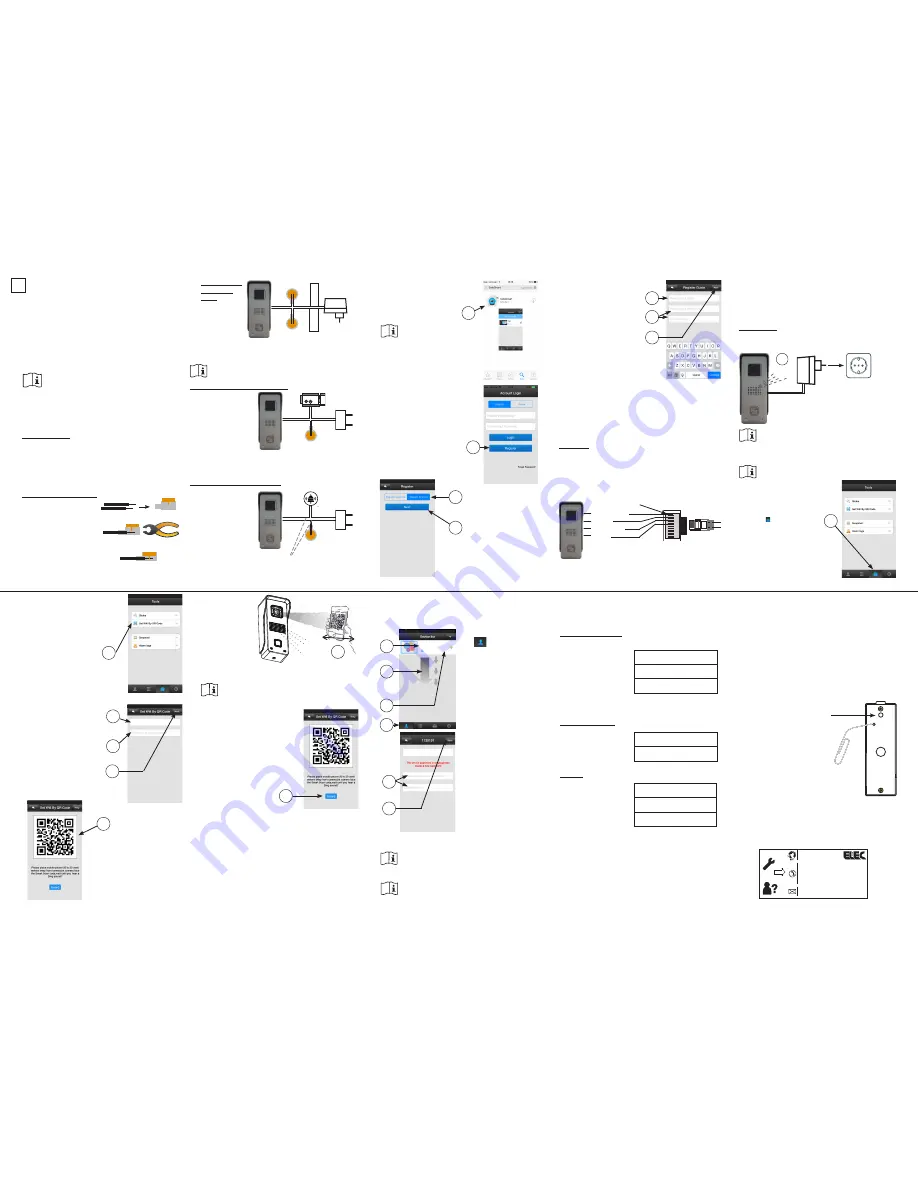
Connect the red wire with the DC12V+ of the power adaptor
and connect the black wire with the DC12V- of the power
adaptor.
Do NOT insert the adaptor into a wall socket yet.
Yellow and purple connecting wires:
Connect these wires
with an electric door
opener according to
the figure below, which
allows you to remotely
open the door via your
smartphone or tablet.
The operating instructions for the electric door opening can
be found in ‘IDC-25 Setup & Operation’.
*: An electric door opener with power source is NOT included.
Grey and white connecting wires:
Connect these wires
with the original door-
bell according to the
figure below, to ensure
the bell keeps function-
ing as before when
somebody rings it.
**: original doorbell
and bell transformer
of the residence or
building.
4.
APP download.
download and install the APP
“SafeSmart” via the ‘App Store’
(see 1)
Attention: If you’re asked
for permission to accept
notifications (messaging) during the
installation of the app, please also
accept that.
5. To create an account.
open the app and click ‘regis-
ter’ (see 2)
select ‘By email’ (see 3)
(registration via mobile
number is not supported)
click ‘Next’ (see 4)
Now insert one of the LAN cable plugs into the 8-pin
contra plug and the other plug of the LAN cable into a
free connection on the router.
Now please continue at chapter 7.
Wi-Fi antenna
Screw the supplied antenna onto the antenna wire of the
camera.
insert the power adaptor of the camera into
a wall socket and wait for approx. 25 sec-
onds until beep tones are emitted (see 8)
Attention: When removing the camera from the
metal holder, please keep the little black anti-
tampering button at the rear depressed, otherwise the
siren will sound to indicate a tampering attempt.
Please refer to chapter 9 if no beep tones are
emitted after 25 seconds.
make sure that the smartphone
or tablet is connected to the Wi-Fi
network
press the button (see 9)
in the APP, click the option
‘Set Wifi by QR code’
(see 10)
click ‘network’ and enter
the network name (see 11)
enter the password of the
network (see 12)
click ‘Next’ (see 13)
the smartphone or tablet
will now show a QR code
which contains the ac-
cess code of the network
(see 14)
now move the
smartphone or
tablet with the QR
code at a distance
of approx. 15 to
20 cm in front of
the camera until
after several sec-
onds a “CHING”
tone is emitted; the
camera has now read the code (see 15)
you may have to increase the brightness of the
smartphone or tablet for a better scan result
click the ‘Heard’ button after
the “Ching” has sounded
(see 16)
the camera will now register itself on the network which
may take several seconds
“Setup successfully” will be briefly shown in the display
after a successful registration.
7. To pair the camera to a smartphone or tablet.
(only for LAN users: insert the power adaptor of the
camera into a 230V wall socket)
click ‘
’ (see 17), swipe
down (see 18) and wait until
the camera is displayed in
the ‘device list’
at the top of the list (see 19)
the device number of the
camera is shown (
in this
example it’s
446589)
press the white part at the
left of the + (see 20)
assign a personal name to
the camera and repeat this
(see 21)
press ‘Save’ to save this
camera (see 22)
***
THE CAMERA IS NOW READY FOR USE ***
If ‘Connection failed’ appears in the display,
please first perform the reset procedure (see
chapter 9) and start again at chapter 6.
See “DCI-25 SETUP” for registering this camera to a
second smartphone or tablet
8. Use the space below to write down the various pass-
words and save this manual in the packaging of this
door camera to keep everything together for future
reference.
create account / log-in:
email address:
(account) password:
account number:
(see instruction 1
in ‘DCI-25 SETUP)
log into the network:
name of the network:
(Wi-Fi) password:
Camera:
device number:
camera name:
camera password:
9. Possible problems when registering the camera on
the network.
As is described at figure 15, the camera obtains the
log-in information via a QR code from the smartphone or
tablet. If for any reason this code must be read again, the
camera must first be reset. Also when no beep tones are
emitted (see figure 8) or when you suspect any fault, the
camera must first be reset.
The reset is performed as follows:
1. Remove the adaptor from the wall socket.
2. Remove the Allen screw at the bottom of the camera
and take the camera out of the holder.
3. Press and hold the anti-
tampering button at the rear
of the camera.
4. Insert the adaptor into a wall
socket and wait for 20 sec-
onds (keep pressing the
anti-tampering button).
5. Use a paperclip to press
and hold the reset button
at the rear of the camera
for approx. 5 seconds until
you here a DING tone; the
camera is now reset.
6. You can now remove the adaptor from
the wall socket and also release the
anti-tampering button.
7. Replace the camera into the holder and fasten the
Allen screw.
8. Now continue at chapter 6.
IDC-25 INSTALLATION
iOS
1. Introduction.
This installation guide describes how the IDC-25 IP door
camera must be installed on the smartphone to see
who’s ringing the doorbell. Please refer to ‘IDC-25 Setup
& Operation’ manual printed on the other side of this user
manual for setup and user instructions.
2. Anti-tampering push-button.
At the rear of the camera you’ll find a small
push-button. As soon as this little push-button
gets released, e.g. because the camera is being removed
from the holder, the camera will emit an alarm tone. So
please remove the adaptor from the wall socket when the
camera is removed from the holder.
3. Electric camera connection.
Push-connectors:
Attention: the supplied push-connectors are one-time
use only. When first registering and setting up and then
later performing the permanent installation, it’s recom-
mended to first connect the wires only temporarily (e.g.
using a lustre terminal). Only use the push-connectors for
permanent placement.
Using the push-connectors:
push the stripped wires
as far as possible into the
connector
now squeeze it tight using
a pair of pincers
the number on the orange cover
has no user function.
enter the email address for
sending the password to in
case it ever gets lost (see 5)
enter your own personal pass-
word twice (see 6)
(max. 27 characters, keep
in mind that upper-case and
lower-case letters and special
symbols are allowed)
click ‘Next’ (see 7)
If the text ‘email
has been registered’ appears at this
point, it means that an account has
already been created for this email address; please enter a
different email address.
6. To register the camera on the network.
You can choose to connect the camera wirelessly, via the
supplied WiFi antenna, with a 2.4GHz router (network) or
through a LAN cable.
LAN cable:
Arrange the 4 wires in the supplied 8-pin contra plug ac-
cording to the figure below and clamp them down by clos-
ing the cover and pushing it tight.
(tip: this can be performed for each wire separately, a
clamped down wire will not be released anymore when
opening the cover)
*** LAN cable is not included.
DC12V+
DC12V
-
Red
Black
Yellow
Purple
*
White
Grey
**
1
*
**
Tip: here the original bell
pusher was connected
2
3
4
5
6
7
1
2
3
4
5
6
7
8
***
the wires must be stripped
after 25 sec.:
‘bi...bi’
8
9
10
netwerk
13
11
12
14
“CHING”
smartphone:10-15cm
tablet: 20cm
15
16
CAM446589
18
20
17
19
CAM446589
21
22
5 sec.
1
Service
Help
Service
Help
WWW.HESDO.NL
NL 073 6411 355
(Lokaal tarief)
BE 03 238 5666
(Lokaal tarief)
(Tarif local)
DE 0180 503 0085
Lokale Festnetzkosten
Hesdo, Australiëlaan 1
5232 BB, ‘s-Hertogenbosch
The Netherlands
WWW.HESDO.NL
NL 073 6411 355
BE 03 238 5666
DE 0180 503 0085
Hesdo, Australiëlaan 1, 5232 BB,
‘s-Hertogenbosch,
The Netherlands
(Lokaal tarief)
(Tarif local)
(Lokaal tarief)
(Lokale Festnetzkosten)
orange/white
orange
green/white
green


