Thank you for purchasing this Panasonic product.
■
The Operating Instructions correspond to the firmware’s main version 1.07 or higher and
network version 1.01 or higher.
■
Before operating this product, please read the instructions carefully and save this manual
for future use.
■
Before using this product, be sure to read “Read this first!” (
x
pages 5 to 11).
DPQP1341ZC/X1
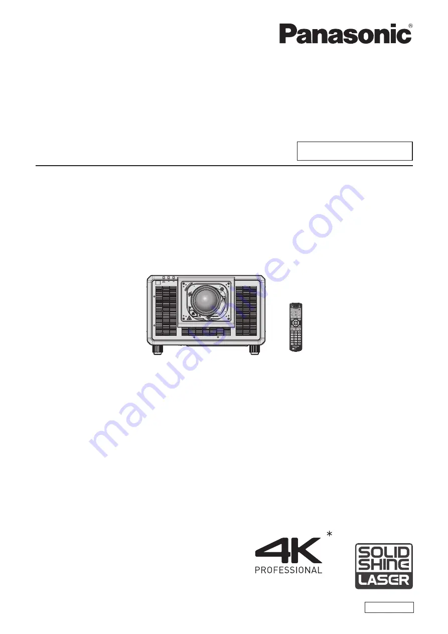
DLP™ Projector
Commercial Use
Operating Instructions
Functional Manual
ENGLISH
Model No.
PT-SRQ35KC
The projection lens is sold separately.
* Resolution is 3 840 x 2 400 dots
(QUAD PIXEL DRIVE: ON)