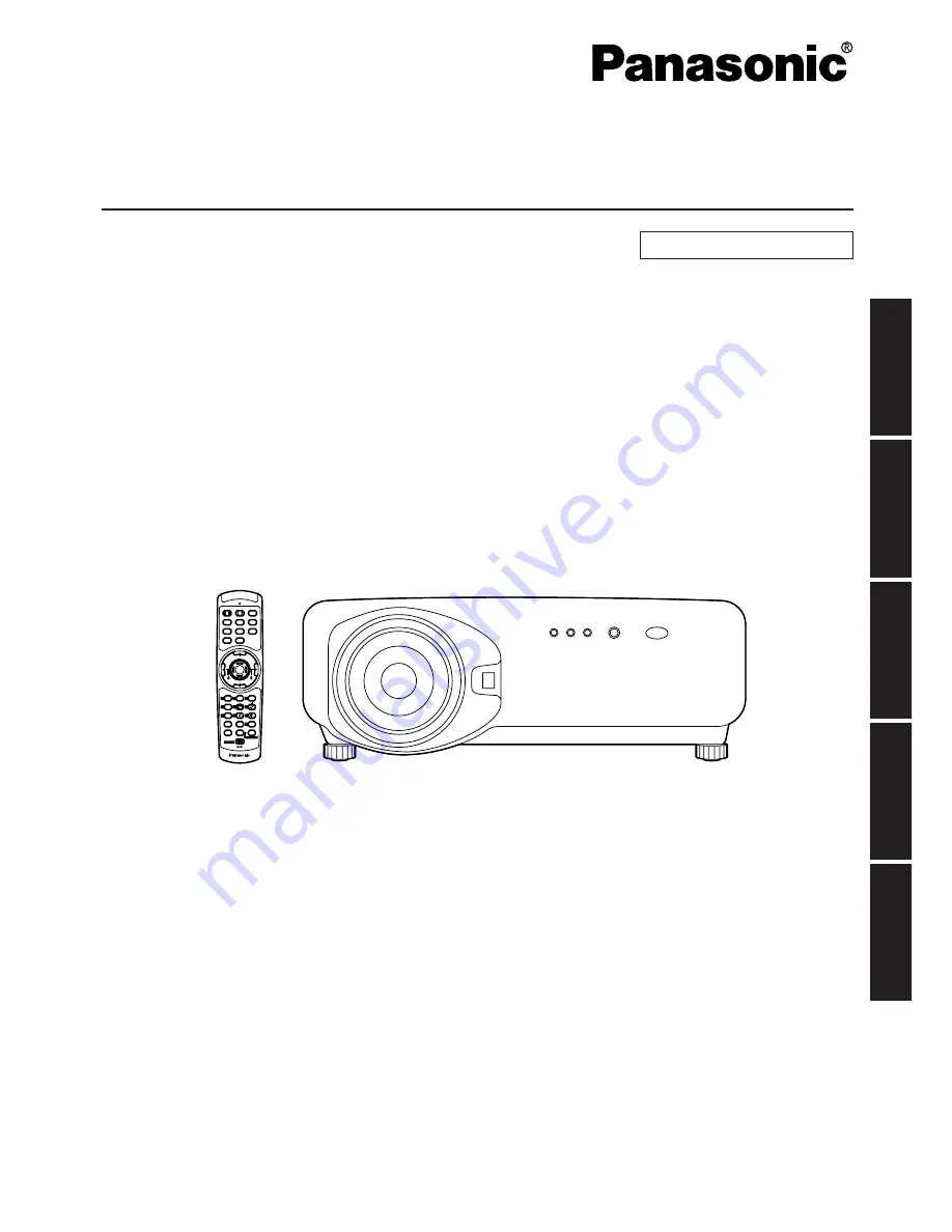
background image

DLP

TM

Based Projector  

Commercial Use

Operating Instructions

Read these instructions completely before operating this unit.

TQBJ 0147-8

POWER

ON

OFF

RGB

1

RGB

2

AUX

MENU

STD

LENS

OSD

1

4

7

2

5

8

3

6

9

0

NEXT

USER

LIGHT

ID ALL

ASPECT

ID SET

Projector

Computer

Numetric

BRIGHT

CONTRAST

ON SCREEN

SYSTEM

SEL

FUNC

1

D.ZOOM

ENTER

PAGE 

UP

PAGE 

DOWN

VIDEO

SHUT

S-

VIDEO

FREEZE

SHUTTER

AUTO

SETUP

LASER ON/OFF

Model No. 

PT-D7700E

PT-DW7000E

ENGLISH

DEUTSCH

FRANÇAIS

ESP

AÑOL

IT

ALIANO

Summary of Contents for PT-D7000E

Page 1: ...POWER ON OFF RGB 1 RGB 2 AUX MENU STD LENS OSD 1 4 7 2 5 8 3 6 9 0 NEXT USER LIGHT ID ALL ASPECT ID SET Projector Computer Numetric BRIGHT CONTRAST ON SCREEN SYSTEM SEL FUNC 1 D ZOOM ENTER PAGE UP PAGE DOWN VIDEO SHUT S VIDEO FREEZE SHUTTER AUTO SETUP LASER ON OFF Model No PT D7700E PT DW7000E ENGLISH DEUTSCH FRANÇAIS ESPAÑOL ITALIANO ...

Page 2: ...r less than 70 dB A according to ISO 7779 WARNING 1 Remove the plug from the wall outlet when this unit is not in use for a prolonged period of time 2 To prevent electric shock do not remove cover No user serviceable parts inside Refer servicing to qualified service personnel 3 Do not remove the earthing pin on the power plug This apparatus is equipped with a three prong earthing type power plug T...

Page 3: ...f severe electrical shock if the cut off plug is inserted into any 13 amp socket If a new plug is to be fitted please observe the wiring code as shown below If in any doubt please consult a qualified electrician WARNING THIS APPLIANCE MUST BE EARTHED IMPORTANT The wires in this mains lead are coloured in accordance with the following code Green and Yellow Earth Blue Neutral Brown Live As the colou...

Page 4: ...n of parts 10 Remote control 10 Front and side of the projector 12 Rear view of the main unit 13 Controls on rear panel 13 Side mounted connection terminals 14 Using the remote control unit 15 Loading dry cells 15 Effective range of remote control operation 15 Setting projector ID number to remote control 16 Using the remote control as a PC mouse 17 Using a wired remote control 17 Installation 18 ...

Page 5: ...ver or modify it in any way High voltages which can cause fire or electric shocks are present inside the projector For any inspection adjustment and repair work please contact an Authorized Service Centre Clean the power cord plug regularly to prevent it from becoming covered in dust If dust builds up on the power cord plug the resulting humidity can damage the insulation which could result in fir...

Page 6: ...ome damaged if struck against hard objects or dropped and injury or malfunctions may result Do not set up the projector in humid or dusty places or in places where the projector may come into contact with smoke or steam Using the projector under such conditions may result in fire or electric shocks When disconnecting the power cord hold the plug not the cord If the power cord itself is pulled the ...

Page 7: ...nce a year If dust is left to build up inside the projector without being cleaned out it can result in fire or problems with operation It is a good idea to clean the inside of the projector before the season for humid weather arrives Ask your nearest Authorized Service Centre to clean the projector when required Please discuss with the Authorized Service Centre regarding cleaning costs Do not reac...

Page 8: ...en surface Draw window curtains or blinds turn off the lightings near the screen or take other proper measures In rare cases wafture can occur on the screen affected by the warm air from the exhaust port depending on the environment Do not touch the surface of the projection lens with bare hand If fingerprints or stains are left on the projection lens surface they are magnified and projected on th...

Page 9: ...ture brightness System 3 PC equipped with a DVI D input module an optional item can be attached to the projector for computer image viewing Realization of high resolution picture System 4 Connection of a signal selector enables to feed a variety of video sources to the projector OFF OFF POWER ON INPUT SELECT 1 2 3 4 5 6 VP ON OFF Signal Selector TW SWS Digital broadcasting tuner or DVD player Cont...

Page 10: ...e SECURITY password ENTER button page 44 Press this button to enter your menu selection or to run function ON SCREEN button This button turns on and off the on screen indication function Standard STD button page 44 Press this button to restore the default factory setting SYSTEM SELECTOR button page 63 System switching can be done Function 1 FUNC1 button page73 This button can control the functions...

Page 11: ...WER ON OFF RGB 1 RGB 2 AUX MENU STD LENS OSD 1 4 7 2 5 8 3 6 9 0 NEXT USER LIGHT ID ALL ASPECT ID SET Projector Computer Numetric BRIGHT CONTRAST ON SCREEN SYSTEM SEL FUNC 1 D ZOOM ENTER PAGE UP PAGE DOWN VIDEO SHUT S VIDEO FREEZE SHUTTER AUTO SETUP LASER ON OFF When the operation mode selector is set to Computer PAGE UP PAGE DOWN buttons These buttons correspond to the PAGE UP PAGE DOWN buttons o...

Page 12: ...mp lights in red when the MAIN POWER switch is turned to I on It turns to green when the POWER ON button of the remote control or the main unit is pressed LAMP1 monitor page 96 This lamp lights up when the time to replace lamp unit 1 is reached It also blinks if something unusual occurs in the lamp circuit Projection lens optional Lens for projecting images on the screen Projection lens cover lock...

Page 13: ...es to video input S VIDEO button page 33 Switches to S VIDEO input SHUTTER button page 42 Press this button to black out the image temporarily MENU button pages 44 and 80 81 Displays and clears the Main Menu It can also return to the previous screen when the menu is displayed Menus can be displayed by holding down the MENU button for at least 3 seconds while the on screen indication function is OF...

Page 14: ... system they can be connected and controlled with a wired remote control cable M3 jack REMOTE2 terminal page 76 The user can remotely control the main unit by using an external control circuit to this terminal D SUB 9 pin female SERIAL IN terminal pages 23 25 67 74 75 This terminal is an RS 232C RS 422 compliant input terminal switching necessary to connect a PC and to externally control the main ...

Page 15: ...n figure 2 The effective control range is approx 7 metres from the beam receiver on the front or rear Do not drop the remote control unit Do not expose remote control unit to any liquid Do not use NiCd batteries Attention When the remote control is aimed at the screen the effective control range may be reduced due to the optical loss by screen reflection The remote control may not function properl...

Page 16: ...tion mode selector switch to Projector However if the ID ALL button is pressed the projector can be controlled regardless of the ID number of the projector simultaneous control mode Using the remote control unit Setting projector ID number to remote control Do not press the ID SET button accidentally or carelessly because the ID number on the remote control can be set even when no projector is aro...

Page 17: ...D EO FR EE ZE SH UT TE R A U T O S E T U P S T D L E N S O S D 1 4 7 2 5 8 3 6 9 0 N E X T U S E R LIG HT ID AL L ID SE T P ro je c to r C o m p u te r Nu m et ric BR IG HT C O N T R A S T O N S C R E E N S Y S TE M S E L FU NC 1 D Z O O M AS PE CT Click button To use the remote control as a mouse please purchase an optional wireless mouse receiver model No ET RMRC2 When multiple main units are co...

Page 18: ...sition Front Side Leveling feet H SH L L H Side view When optional ceiling mount bracket ET PKD75 Screen unit mm 438 558 237 L SW 314 86 140 175 468 117 L1 Top view Screen unit mm Installation geometry When planning the projector and screen geometry refer to the figures below and the information on the next page for reference After the projector is roughly positioned picture size and vertical pict...

Page 19: ...aximum ET D75LE1 1 5 2 0 1 Minimum Maximum ET D75LE2 2 0 3 0 1 Minimum Maximum ET D75LE3 3 0 5 0 1 Minimum Maximum ET D75LE4 5 0 8 0 1 ET D75LE5 0 8 1 Projection distance L Zoom lens Fixed focus lens 21 14 24 22 27 29 30 36 36 50 45 72 61 08 76 44 91 79 107 15 122 51 153 23 183 95 11 09 12 73 14 37 16 01 19 29 24 21 32 40 40 60 48 80 57 00 65 19 81 59 97 98 Minimum Maximum ET D75LE8 8 0 15 0 1 Eff...

Page 20: ... 45 68 96 7 94 9 09 10 24 11 39 13 69 17 15 22 90 28 66 34 42 40 17 45 93 57 44 68 95 4 73 5 42 6 11 6 80 8 18 10 24 13 69 17 14 20 58 24 03 27 48 34 37 41 26 4 72 5 41 6 10 6 79 8 17 10 23 13 68 17 13 20 57 24 02 27 47 34 36 41 25 3 14 3 60 4 06 4 52 5 44 6 81 9 11 11 41 13 71 16 01 18 30 22 90 27 49 3 10 3 56 4 02 4 48 5 39 6 77 9 05 11 34 13 63 15 92 18 21 22 78 27 36 2 32 2 66 3 01 3 35 4 04 5...

Page 21: ... Screen diagonal inch 0 0958 Maximal distance L 0 1123 x Screen diagonal inch 0 1216 Minimal distance L 0 1031 x Screen diagonal inch 0 1158 Maximal distance L 0 1639 x Screen diagonal inch 0 1013 4 3 ET D75LE4 5 0 8 0 1 16 9 Minimal distance L 0 1786 x Screen diagonal inch 0 3862 Maximal distance L 0 3346 x Screen diagonal inch 0 3598 Minimal distance L 0 1640 x Screen diagonal inch 0 3862 Maxima...

Page 22: ...e a time base corrector TBC must be connected The projector accepts the following signals video S Video analogue RGB and digital signals from the PC Some PC models cannot be connected to the projector The pin out and signal names of the S VIDEO IN terminal are shown in the diagram below The pin out and signal names of the RGB2 input terminal are shown in the diagram below Outside view Pin No Groun...

Page 23: ...o PR terminal Blue connected to PB terminal Green connected to Y terminal Video deck TBC built in Example of connecting with VIDEO devices When connecting with a video deck be sure to use the one with a built in time base corrector TBC or use a TBC between the projector and the video deck If nonstandard burst signals are connected the image may be distorted If this is the case connect a TBC betwee...

Page 24: ... R RS 232C G RS 422 R IN RGB 2 IN RGB 2 IN I F PC PC Control PC When the main power of the main unit is turned off also turn off the power of the PC Note Attention For the specifications of the RGB signals that can be applied from the PC see the data sheet on page 104 If your PC has the resume feature last memory the computer may not function properly until the resume capability is disabled Exampl...

Page 25: ...r TW SWS Digital broadcasting tuner DVD player Signal selector Video deck TBC built in Notebook computer Control PC Note When multiple signals of the same type are switched and input to RGB1 IN for example when switching multiple high vision signals for usage use a dedicated signal selector When the signal selector is connected to the projector with a RS 232C cable signals can be used separately a...

Page 26: ...ted SD SDI input module ET MD77SD1 BNC input x 1 BNC output x 1 HD SD SDI input module ET MD77SD3 BNC input x 1 BNC output x 1 DVI D input module ET MD77DV DVI D 24p input x 1 RJ 45 input x 1 RJ 45 input x 1 RJ 45 input x 1 Network module ET MD77NT RJ 45 input x 1 1 HDCP High bandwidth Digital Content Protection HDCP is a specification for encoding digital image signals which was developed to prot...

Page 27: ...screws Input module Slot Tighten the two screws Remove the slot cover Insert the input module Fix the input module Register the input signal This projector needs to register the type of input signal after the installation of the input module For details on the registration of the input signals refer to pages 38 41 ...

Page 28: ...n video deck DVD player Business digital VCR PC HD SD SDI input module ET MD77SD3 Connecting signals to the input module When installing the projector it is necessary to connect signals to the input module in accordance with the connecting equipment Refer to the following diagram to establish proper signal connection Installation of input module optional ...

Page 29: ... signal specifications Normally use SYSTEM SELECTOR in AUTO Automatic detection may malfunction if any unstable signal is connected If this happens switch to a system that is compatible with the signal format using the SYSTEM SELECTOR button Use the SYSTEM SELECTOR button to toggle the systems of the input module that supports two types of signal specifications Upon toggling the input signals are ...

Page 30: ...ection may malfunction if any unstable signal is connected If this happens switch to a system that is compatible with the signal format using the SYSTEM SELECTOR button Use a 5CFB or superior cable for connection to transmit the image information without error Example 5CFB 5CFTX 7CFB etc AUTO 576i 480i 720 50p 1 080 24sF 1 080 25p 1 080 30p 1 080 60i 1 035 60i 720 60p 1 080 24p 1 080 50i HD SD SDI...

Page 31: ... 0 T M D S data 0 T M D S data 0 5 shield T M D S clock shield T M D S clock T M D S clock Connecting signals to the DVI D input module Pin assignments and signal names of DVI D input terminal are listed in the table at right The DVI D signal input module supports only a single link The HDMI DVI conversion cable is required to connect an HDMI compliant device The EDID mode setting must be selected...

Page 32: ...nsert the lens and turn it clockwise until it clicks into place Insert the tab on the projection lens cover into the projector and mount the projection lens cover while pressing the lock button How to remove the projection lens While pressing the lock button on the projection lens cover pull the cover forward to remove it While holding down the lock button turn the projection lens counterclockwise...

Page 33: ...to start projection The temperature monitor TEMP lamp lights up during the warm up period When the warm up is completed the temperature monitor TEMP lamp turns off and the image is projected on the screen If the surrounding temperature is very low and the warm up period exceeds five minutes the control determines it as an abnormal condition and turns off the power automatically If this happens rai...

Page 34: ...the light source lamp if the lamp is in the process of cooling down after turning off the power supply To light up the lamp turn on the power supply again when the lamp has been cooled sufficiently The projector consumes approximately 15 watts of power even in standby mode after the cooling fan stops Power indicator lamp lit in red If you re power the projector after shutting off the main power in...

Page 35: ...te control or on the control panel of the main unit Pressing the button changes the setup screen in the order of LENS FOCUS LENS ZOOM and LENS SHIFT Choose an item and adjust it using buttons How to adjust the lens Caution Be careful not to catch your fingers between the lens and shroud when shifting the lens How to adjust the lens focus lens zoom and lens shift optical shift Adjustment range afte...

Page 36: ... mm diagonal hexagon Vup H left H right Vbottom a b c Fixing screws Lens bracket V up is out of focus V bottom is out of focus The instructions within parentheses apply to ceiling mount installation Turn counterclockwise Turn counterclockwise H right is out of focus H left is out of focus Turn counterclockwise Turn counterclockwise Turn counterclockwise Turn counterclockwise Turn counterclockwise ...

Page 37: ...ay have been shifted even when the adjustment ended normally In this case manually adjust the CLOCK PHASE If an image with blurred edges or a dark image is supplied a message INCOMPLETE appears indicating the automatic adjustment was unsuccessful In this case manually adjust the items of INPUT RESOLUTION CLOCK PHASE and SHIFT For specific signals and long sideways or landscape signals such as 16 9...

Page 38: ... screen will be displayed Select SIGNAL LIST with the and buttons Note MAIN MENU PICTURE POSITION ADVANCED MENU LANGUAGE OPTION TEST PATTERN SIGNAL LIST SECURITY MENU SELECT ENTER SUB MENU REGISTERED SIGNAL LIST A1 SVGA72 A1 RGB1 A2 SVGA72 A2 RGB1 A3 SVGA72 A3 RGB1 A4 SVGA72 A4 RGB1 A5 SVGA72 A5 RGB1 A6 SVGA72 A6 RGB1 A7 SVGA72 A7 RGB1 A8 SVGA72 A8 RGB1 SELECT ENTER DETAILS STD DELETE REGISTERED S...

Page 39: ...H 48 08kHz fV 72 17Hz SYNC STATE H POS V POS ENTER EXECUTE MENU ESC RENAME NAME SVGA72 A2 MEMORY NO A2 S S NO INPUT NO RGB1 fH 48 08kHz fV 72 17Hz SYNC STATE H POS V POS NEXT FIGURE FONT SELECT ENTER SET MENU ESC Press the STD button The ENTRY SIGNAL CLEAR screen will be displayed If the data is not to be cleared press the MENU button to return to the REGISTERED SIGNAL LIST screen Press the ENTER ...

Page 40: ...fV 60 00Hz SYNC STATE H POS V POS ENTER EXECUTE MENU ESC Press the USER button on normal screen menu is not displayed A Check sub memory registration screen will appear if sub memory has not been registered The screen will show a list of the sub memory registered for the currently entered signal Select the SUB MEMORY number stored with the and buttons in the SUB MEMORY LIST Press the ENTER button ...

Page 41: ...ode A1 A2 H7 and H8 signals are registered displays the sub memory number Details of registered signal Restrictions The maximum sub memory items that can be registered for the projector are 96 including the basic signal Note REGISTERED SIGNAL STATUS NAME SXGA60 A1 MEMORY NO 1 2 S S NO INPUT NO RGB1 fH 48 00kHz fV 60 00Hz SYNC STATE H POS V POS ENTER CHANGE NANE NAME RGB MEMORY NO A1 1 2 S S NO INP...

Page 42: ... presentation Press the D ZOOM button of the remote control The image is zoomed in Change the magnification with the D ZOOM button The magnification can be adjusted from 1 0 to 3 0 times Use buttons to move the magnified image To restore the original image press the MENU button The digital zoomed state cannot be stored in memory If the input signal format is changed while in digital zoom mode the ...

Page 43: ...1 A6 SVGA72 A6 RGB1 A7 SVGA72 A7 RGB1 A8 SVGA72 A8 RGB1 SELECT ENTER DETAILS STD DELETE OPTION PROJECTOR ID 2 SETTING FRONT F LAMP SELECT DUAL LAMP POWER HIGH RS232C SETTING OSD POSITION 2 SYSTEM INFORMATION COLOR MATCHING OFF VIDEO SETTING AUTO SETUP MENU SELECT CHANGE ADVANCED MENU DIGITAL CINEMA REALITY AUTO FORMAT SMPTE BLANKING INPUT RESOLUTION CLAMP POSITION EDGE BLENDING OFF SYNC TERM 75 RA...

Page 44: ... MENU SELECT ADJUST CONTRAST 32 Returning to the previous screen When the MENU is on the screen pressing the MENU button returns to the previous page When the MAIN MENU is on the screen pressing the MENU button clears all menus from the screen Menu items shown in gray characters Some menu items may not be valid for certain signal formats applied to the projector The menu items that cannot be adjus...

Page 45: ...screen will be displayed Select PICTURE MODE with the buttons Switch PICTURE MODE with the buttons DYNAMIC The picture becomes suitable for the use in well lighted areas GRAPHIC The picture becomes suitable for input from to the personal computer USER The COLOUR TEMP and GAMMA settings can be adjusted STANDARD The picture becomes suitable for moving images in general CINEMA The picture becomes sui...

Page 46: ...be displayed for CONTRAST and BRIGHT by the remote control Refer to the following table To register the picture mode settings which have been adjusted and use them as the presettings follow the procedure on the next page from step Item Adjustment Adjustment range Remarks CONTRAST Raises the picture brightness and the picture becomes clearer Lowers the picture brightness and weakens the picture Max...

Page 47: ...settings as presettings The screen settings which have been adjusted by following the adjustment procedure on the previous page can be registered Press the MENU button The MAIN MENU screen will be displayed Select PICTURE with the buttons Press the ENTER button Select OK with the buttons Press the ENTER button Press the ENTER button The PICTURE screen will be displayed If the registered picture mo...

Page 48: ... USER in step Press the ENTER button The DYNAMIC IRIS screen will be displayed Select AUTO IRIS MANUAL IRIS or DYNAMIC GAMMA with the buttons Adjust the compensation amount with the buttons The contrast is set to the maximum level when DYNAMIC IRIS is set to 3 Note Aperture compensation and signal compensation amounts 1 Low 2 Intermediate 3 High USER See below OFF No compensation AUTO IRIS Automat...

Page 49: ...justment is not successful press STD standard button when the individual adjustment screen is displayed to restore the factory default setting only for the displayed item The colour temperature cannot be adjusted for the internal test pattern refer to page 77 Be sure to project the input signal when adjusting the colour temperature When any setting other than OFF has been selected for colour match...

Page 50: ...on Sharpens the outline of the image Switches the gamma modes Operation Four types OFF no correction 1 low 2 middle 3 high factory default 2 Noise reduction Switches the noise reduction effect mode Note Noise reduction cannot be adjusted with analogue RGB input DVI input or network input Separate software is required to select USER1 and USER2 as the gamma setting Consult your dealer To display pic...

Page 51: ...ION with the buttons MAIN MENU PICTURE POSITION ADVANCED MENU LANGUAGE OPTION TEST PATTERN SIGNAL LIST SECURITY MENU SELECT ENTER SUB MENU Press the ENTER button The POSITION screen will be displayed Select SHIFT with the buttons SHIFT V 0 H 0 ADJUST Press the ENTER button The SHIFT screen will be displayed Adjust the position with the buttons Press the MENU button three times The on screen indica...

Page 52: ...R SUB MENU ZOOM INTERLOCKED OFF V 100 H 100 HV 100 MENU SELECT CHANGE Press the ENTER button The SIZE adjustment screen will be displayed Select the desired item with the buttons Adjust with the buttons Size adjustment Procedure of adjustment Press the ENTER button The POSITION screen will be displayed Select SIZE with the buttons Using the buttons select the size mode For details on the size mode...

Page 53: ... displayed by converting it into the panels aspect ratio 4 3 for PT D7700E and 16 9 for PT DW7000E VID AUTO The projector identifies the video ID VID embedded in the picture signals and displays the picture by automatically switching the screen sizes between 4 3 and 16 9 This function is effective for the video and S video input S1 AUTO The projector identifies the S1 signal and displays the pictu...

Page 54: ...E with the buttons Press the ENTER button The KEYSTONE screen will be displayed Adjust the KEYSTONE horizontally with the buttons The value changes from 0 to 127 Adjust the vertical LINEARITY with the buttons The value changes from 0 to 127 Adjust the LINEARITY after adjusting the KEYSTONE The variable range of the LINEARITY changes in response to the adjusted value of the KEYSTONE Pressing STD st...

Page 55: ...ease the vertical resolution when the PAL or SECAM 576i signal input or the NTSC 480i signal input is applied Procedure of adjustment Press the MENU button The MAIN MENU screen will be displayed Select ADVANCED MENU with the buttons Press ENTER button The ADVANCED MENU screen will be displayed Select DIGITAL CINEMA REALITY with the buttons OFF Unforced cinema processing AUTO Performs automatic det...

Page 56: ...Select the desired item for adjustment with the buttons Adjust blanking with the buttons The value changes from 0 to 511 Press button to move the blanking zone upward button to downward Press button to move the blanking zone upward button to downward Press button to move the blanking zone to the right button to the left Press button to move the blanking zone to the right button to the left When co...

Page 57: ... to the type of the input signal If vertical stripes appear on the screen or the image is partly missing increase or decrease the displayed value while observing the screen to achieve the optimal value Adjusting the input resolution Input resolution adjustment achieves the best image when the screen flickers or halo is observed around the contour Procedure of adjustment Press the MENU button The M...

Page 58: ...ark areas are displayed in green The optimal value is the point where the green area becomes dark and clear Adjusting the clamp position Use the clamp position adjustment to achieve the optimal value when dark areas of the image are crushed or displayed in green Procedure of adjustment Press the MENU button The MAIN MENU screen will be displayed Select ADVANCED MENU with the buttons Press the ENTE...

Page 59: ...re these lines overlap Red line Red line Green line Green line Adjustment marker When the MARKER is set to ON the image position adjustment marker is displayed The optimal point is the position where the red line of one frame overlaps the green line of the other frame Notice The correction widths of the jointed frames must be the same value all the time The optimal joint cannot be achieved if the ...

Page 60: ... making the brightening of the BRIGHT level in those areas where the pictures overlap less conspicuous when multi screens have been configured using edge blending The optimal point is where after the BRIGHT INSIDE has been adjusted the compensation amount is the same for the BRIGHT levels in the areas where the pictures overlap and where the pictures do not overlap If after the BRIGHT INSIDE adjus...

Page 61: ...U screen will be displayed Select RASTER POSITION with the buttons Press the ENTER button The RASTER POSITION screen will be displayed Adjust the position with the and buttons Press the MENU button three times The on screen indications disappear and the normal screen appears again Pressing button will move the image to the right Pressing button will move the image to the left When 5 4 pictures are...

Page 62: ...DVANCED MENU LANGUAGE OPTION TEST PATTERN Press the ENTER button The LANGUAGE screen will be displayed Select the desired language with the buttons Press the ENTER button to establish your selection When this is selected the language display will turn a light green Menus setting items adjustment screens and control button names will be displayed in the language the user chooses The available langu...

Page 63: ...1 NTSC PAL SECAM PAL60 NTSC4 43 AUTO2 NTSC PAL M PAL N For the setting of AUTO1 For the setting of AUTO2 AUTO 576i 480i 720 50p 1 080 24sF 1 080 25p 1 080 30p 1 080 60i 1 035 60i 720 60p 1 080 24p 1 080 50i When the STD standard button is pressed while changing the system mode with the SYSTEM SELECTOR the projector automatically returns to AUTO1 AUTO2 or AUTO AUTO 1 Selection is automatically made...

Page 64: ...to 64 If the projectors are given ID numbers their remote controls must be assigned the same ID numbers respectively If the ID number of a projector is set to ALL it can be controlled by the remote control or the PC with any ID number If multiple projectors are used and some of them have their IDs set to ALL they cannot be controlled separately from the projectors with other ID numbers For details...

Page 65: ...NU LANGUAGE OPTION TEST PATTERN SIGNAL LIST SECURITY MENU SELECT ENTER SUB MENU Press the MENU button The MAIN MENU screen will be displayed Select OPTION with the buttons Press the ENTER button The OPTION screen will be displayed Select SETTING with the buttons and choose a projection scheme with the buttons Each time or button is pressed the types of projection scheme together with its indicatio...

Page 66: ... power consumption reduce operating noise and extend lamp service life LOW is set automatically when Long Life Lamp Units are used If any of SINGLE LAMP 1 and LAMP 2 has been selected when a currently lit lamp expires or is turned off due to the elapsed time of lamp lighting exceeding 1500 hours with the lamp output set at HIGH the other lamp will be turned on If DUAL has been selected when either...

Page 67: ... NEXT Press the MENU button The MAIN MENU screen will be displayed Press and buttons to select OPTION Press the ENTER button The OPTION screen will be displayed Press and buttons to select RS232C SETTING Press the ENTER button The RS232C SETTING screen will be displayed Press and buttons to select communication conditions Press and buttons to confirm the setting Press the MENU button three times T...

Page 68: ...s with the buttons These values can be adjusted from 0 to 2048 3COLORS R R 2048 G 0 B 0 MENU SELECT ADJUST Adjustment The effects of correcting the adjustment colour When tuning the correction colour that is the same as the adjustment colour the brightness of the adjustment colour changes When tuning the correction colour RED RED is added to or reduced from the adjustment colour When tuning the co...

Page 69: ...with the buttons Press the ENTER button The OPTION screen will be displayed Select COLOR MATCHING with the buttons Select MEASURE with the buttons Press the ENTER button The MEASURE MODE screen will be displayed Use the colorimeter to measure the luminance Y and chromaticity coordinates x y Select the colours with the buttons and select their values with the buttons After all the data has been inp...

Page 70: ...1 152 x 870 1 280 x 960 1 280 x 1 024 1 600 x 1 200 1 400 x 1 050 720 x 400 848 x 480 1 280 x 720 1 120 x 750 1 376 x 768 1 600 x 1 024 Video setting This feature allows the user to select the signaling system according to the connected device Select VIDEO SETTING from the OPTION screen and press the ENTER button The VIDEO SETTING screen will be displayed Use the buttons to select VIDEO or S VIDEO...

Page 71: ... will be displayed Select OUTPUT RESOLUTION with the buttons Auto signal When unregistered signals are to be input frequently because the unit is used at conferences or other venues the screen display position can be adjusted automatically without having to press the AUTO SET UP button on the remote control each time Press the MENU button The MAIN MENU screen will be displayed Select OPTION with t...

Page 72: ...he subwindow Type The user can select the window that is displayed by priority when two windows overlap MAIN WINDOW The main window is displayed by priority SUBWINDOW The subwindow is displayed by priority Linearity The user can select the window to apply the linearity correction when the P IN P function and the keystone distortion correction function are both used simultaneously MAIN WINDOW The l...

Page 73: ... S VIDEO input RGB input EDID1 SD EDID1 HD SD HD EDID1 SD EDID1 HD EDID2 SD YCbCr input HD YPbPr input RGB input YCbCr input YPbPr input RGB input YCbCr input YPbPr input RGB input YCbCr input YPbPr input ET MD77SD1 1 2 3 4 1 2 3 4 List of P IN P P in P Picture in Picture combinations are enabled P in P Picture in Picture combinations are disabled 1 480i 576i 2 720 60p 720 50p 1 035 60i 1 080 60i ...

Page 74: ...ion 9 600bps None 8 bits 1 bit None None PC D Sub 9 pin male Communication cable D Sub 9 pin male D Sub 9 pin female Communication cable Terminal section on Projector 1 Terminal section on Projector 2 D Sub 9 pin female D Sub 9 pin female D Sub 9 pin male D Sub 9 pin male SERIAL IN OUT RS 232C G RS 422 R RS 232C G RS 422 R SERIAL IN OUT RS 232C G RS 422 R RS 232C G RS 422 R When the wrong command ...

Page 75: ...n PON are invalid While the lamp is ON and being controlled a PON command will not be accepted Parameter VID VIDEO SVD S VIDEO RG1 RGB1 RG2 RGB2 AUX AUX Parameter 0 DUAL 1 SINGLE 2 LAMP 1 3 LAMP 2 Parameter 0 DUAL 1 SINGLE 2 Only LAMP 1 is on 3 Only LAMP 2 is on Parameter 0 HIGH 1 LOW Remarks Command Function of command PON POF I I S QSL LPM OLP SINGLE will use the lamp LAMP 1 or LAMP 2 with short...

Page 76: ... a different room STANDBY ON LAMP Remote terminal External control Remote terminal External control RGB1 VIDEO RGB2 S VIDEO Using the REMOTE 2 terminal Names of terminals GND POWER RGB1 RGB2 VIDEO S VIDEO AUX SHUTTER RST SET Open H Controlled by remote control OFF Other OFF Short L Controlled by external contact ON AUX S VIDEO VIDEO RGB2 RGB1 ON GND 9 1 2 4 5 6 7 8 3 Other Other Other Other The PO...

Page 77: ... with the buttons Search through the various types of test patterns with the buttons Cycle of displayed internal test patterns MENU screen All white MENU screen All black MENU screen Flag MENU screen Flag inversion MENU screen Colour bars MENU screen Focus MENU screen Window inversion MENU screen Window MENU screen Entry screen MAIN MENU PICTURE POSITION ADVANCED MENU LANGUAGE OPTION TEST PATTERN ...

Page 78: ...URITY with the buttons Select PASSWORD with the buttons Switch PASSWORD with the buttons ON Password entry is enabled OFF Password entry is disabled Press the ENTER button The PASSWORD screen will be displayed For first time use Press the and buttons in this order and then press the ENTER button When the password has already been changed Enter the new password and press the ENTER button Note Only ...

Page 79: ...can be changed Setting the text The set text can be permanently displayed below the pictures being projected Changing the text The characters displayed in the text can be changed when ON has been selected as the TEXT DISPLAY setting Select PASSWORD CHANGE with the buttons Select TEXT CHANGE with the buttons Press the ENTER button The PASSWORD screen will be displayed Set the password with the and ...

Page 80: ...ating section of the main unit Setting the on screen indication function Procedure of setting Hold down the MENU button for 3 or so seconds If the on screen function is OFF the on screen indication will now appear and the CP OPTION item will be added to the main menu Select CP OPTION with the buttons Press the ENTER button The CP OPTION screen will be displayed Select OSD with the buttons Select O...

Page 81: ...unction is OFF the on screen indication will now appear and the CP OPTION item will be added to the main menu Select SYSTEM SELECTOR with the buttons Press the ENTER button The SYSTEM SELECTOR screen will be displayed Select one of the following inputs for setting the system format with the buttons RGB1 RGB2 VIDEO S VIDEO AUX Note Only the inputs enabling the system format to be selected are actua...

Page 82: ...ld be Internet Explorer 6 0 or later or Netscape Communicator 7 0 or later To use the E mail function communication with E mail server must be established Make sure that E mail feature is available in your system Use a straight insulated LAN cable which supports category 5 or above The length of LAN cable must be 100 m or shorter Name and function of network function parts LAN cable straight Proje...

Page 83: ...YSTEM INFORMATION COLOR MATCHING 3COLORS VIDEO SETTING NETWORK SETTING MENU SELECT ENTER SUB MENU NETWORK SETTING HOST NAME PROJECTOR DHCP OFF IP ADDRESS 192 168 0 8 PORT 80 NET MASK 255 255 255 0 GATEWAY 192 168 0 1 MAC ADDRESS 00 00 00 00 00 00 STORE MENU SELECT ENTER ADJUST Press the ENTER button The NETWORK SETTING screen will be displayed Select items with the buttons and press the ENTER butt...

Page 84: ...Enter the gateway address if DHCP server is not used Displays the MAC address Media Access Control Address which is proper to the network device This function may be needed when to use the DHCP server Display of host name and setting DHCP client function Display of IP address and setting Display and setting of the port number for connection with the Web browser Display of net mask and setting Disp...

Page 85: ...r the IP address set by the projector into the URL input field of the Web browser Enter user1 in the user name field and enter panasonic lower case in the password field Press OK and the top page will appear Password change page Click Change password Old password input field New password input field New password input field re enter for confirmation Button for executing password change Button for ...

Page 86: ...ton Click this item and the update page of the projector s firmware appears E mail set up button Click this item and an E mail setting page appears Monitor information button Click this item and the status of the projector is displayed OSD On screen Display display non display Use these to select the input signals System type switching Network set up button Click this item and a network set up pag...

Page 87: ...he on screen description on the right of the control page when control is finished Monitor information page Click Projector control then Status information to display the Status information page This page displays the projector statuses established for the items shown below Displays the input switching status Displays temperature of projector s intake air Displays temperature inside the projector ...

Page 88: ...re is too high It may be that the projector is being used where the ambient temperature is high such as near a heating appliance The exhaust air temperature is too high It may be that the projector s ventilation holes are blocked The lamp runtime has exceeded the prescribed cumulative time and it is now time to replace the lamp The lamp has failed to light Wait a short while for the lamp to cool o...

Page 89: ...ning temperature is reached again The user can enter the location of for example the installed projector so that the recipient may easily identify the originator of the E mail maximum 63 characters The user can modify the threshold temperature for sending temperature warning mail If the temperature rises above the set value control sends temperature warning mail Enter the E mail address of your de...

Page 90: ...n the field INPUT AIR TEMPERATURE intake air temperature has reached the value set in the field OUTPUT AIR TEMPERATURE exhaust temperature has reached the value set in the field Check these boxes when E mail is to be sent periodically to two E mail addresses E mail will be sent at the times and on the days checked Button to update settings DNS server set up page Click Network set up then DNS serve...

Page 91: ...nput characters Alphanumeric characters A Z a z 0 9 hyphen period POP server user name field Button to update settings POP server password field Ping test page This page makes it possible to check whether the network is connected to the E mail server POP server DNS server etc Click Network set up then Ping test to display the Ping test page Enter the IP address of the server to be tested Button fo...

Page 92: ...MPERATURE OK LAMP2 REMAIN TIME OK LAMP1 REMAIN TIME OK Contents of mail sent Mail with the contents shown below is sent when the E mail settings have been established Subject Panasonic projector report ERROR Panasonic projector report ERROR Projector Type D7700 check system MAIN CPU BUS OK FAN OK OPTICS MODULE TEMPERATURE OK INPUT AIR TEMPERATURE OK OUTPUT AIR TEMPERATURE OK LAMP2 REMAIN TIME OK L...

Page 93: ...dress if DHCP server is not used Enter the net mask if DHCP server is not used Enter the port number here Number 80 is normally used Enter the gateway address if DHCP server is not used Enter the name of the projector here Enter the host name here if it is required when the DHCP server is going to be used for instance If the time becomes incorrect immediately after setting the correct time then th...

Page 94: ...nsferred The time taken will differ depending on the network conditions Displays the current version Displays the updated version Check the updated version against the current version and if everything is in order press the Write button Version data rewriting is now commenced Do not turn off the power while the version data is being rewritten Messages such as the ones shown below appear during dat...

Page 95: ...ayed To cancel press the MENU button The NETWORK SETTING screen will be displayed Press the ENTER button The IP address password E mail settings and all the other network function settings are returned to the factory defaults OPTION PROJECTOR ID 2 SETTING FRONT F LAMP SELECT DUAL LAMP POWER HIGH RS232C SETTING OSD POSITION 2 SYSTEM INFORMATION COLOR MATCHING 3COLORS VIDEO SETTING NETWORK SETTING M...

Page 96: ...edure on page 34 and clean the air filter refer to page 97 Did you turn on the power when the ambient temperature was low approx 0 C Wait about five minutes in the current status Install the unit in a location having an ambient temperature from 0 to 40 C Lighting in red lamp unit ON Remedial measure Blinking in red 2 times High temperature inside Standby condition Blinking in red 3 times Cooling f...

Page 97: ...r filter Do not to suck in the air filter itself The air filter must be fitted in place when using the projector Using the projector without the air filter fitted inside dirt and dust are sucked into the projector causing failure Attention Attention If cleaning cannot remove the dust completely then it is a sign to replace the air filter Consult the dealer In addition when the lamp unit is replace...

Page 98: ...vidual lamps and working conditions lamps may reduce their life affected by the times of lighting and the intervals between previous lighting and next lighting Therefore it is strongly recommended for the user to keep a spare bulb If your lamp unit is not replaced after 1 300 hours 2 with the lamp output set at HIGH power supply will be turned off automatically at the time of 1 500 hours 1 enterin...

Page 99: ... until the screws turn freely Then hold the handle of the lamp unit and gently pull it out from the projector Caution The lamp unit will be hot after it has been used You might get burned if you touch it while it is still hot 5 Install the new lamp unit 6 Use a Phillips screwdriver to securely tighten the two lamp unit fixing screws for each lamp unit 7 Install the lamp unit cover and then use a P...

Page 100: ...y the OPTION screen and select SYSTEM INFORMATION with the and buttons 12 Press the ENTER button The SYSTEM INFORMATION screen will be displayed 15 Press the ENTER button When OK is displayed press the ENTER button The used hours of the specified lamp unit will be reset to zero When more than one lamp has been replaced repeat the procedure from step 14 MAIN MENU PICTURE POSITION ADVANCED MENU LANG...

Page 101: ...ur strength and colour tint correctly adjusted Refer to page 46 Is the device s connected to the projector adjusted correctly Pale colour bad colour tint Are dry batteries consumed Is polarity correct in battery setting Refer to page 15 Are there any obstacle between the remote control and the beam receiving window Refer to page 15 Are you trying to operate the remote control beyond the effective ...

Page 102: ...ically 24 Hz 1 080 30p horizontally 33 75 kHz vertically 30 Hz 1 080 25p horizontally 28 13 kHz vertically 25 Hz 1 080 24sF horizontally 27 kHz vertically 48 Hz HD SYNC VD terminals are not compliant with 3 value composite SYNC Colour system 7 standards NTSC NTSC4 43 PAL PAL N PAL M SECAM PAL60 Screen size 70 inch 600 inch Screen aspect ratio 4 3 Projection scheme Menu selectable from front rear c...

Page 103: ...abinet Molded resin Outside dimensions Width 530 mm Height 200 mm Depth 569 mm Mass Working environment condition 2 Ambient temperature 0 C to 40 C 0 C to 35 C when setting for lamp power is HIGH and lamp select is DUAL Ambient humidity 10 to 80 no condensation Remote control Power source Operation range Mass Outside dimensions Option Hanging attachment For high ceiling ET PKD75 Hanging attachment...

Page 104: ...0 88 9 60 0 72 0 75 0 60 0 74 6 75 0 60 0 60 0 59 9 50 0 59 9 50 0 Applicable input signal data Display mode VGA400 VGA480 XGA MXGA SVGA SXGA SXGA UXGA MAC16 MAC21 1080 60i 720 60p 480i 576i 480p 576p Number of displayed dots Horizontal scanning frequency kHz Vertical scanning frequency Hz The number of display dots of the PT D7700E is 1 400 x 1 050 If signals with a number of display dots differi...

Page 105: ...105 Outside dimensions ENGLISH 540 29 200 530 Units mm ...

Page 106: ...c products and batteries should not be mixed with general household waste For proper treatment recovery and recycling of old products and used batteries please take them to applicable collection points in accordance with your national legislation and the Directives 2002 96 EC and 2006 66 EC By disposing of these products and batteries correctly you will help to save valuable resources and prevent ...

Reviews: