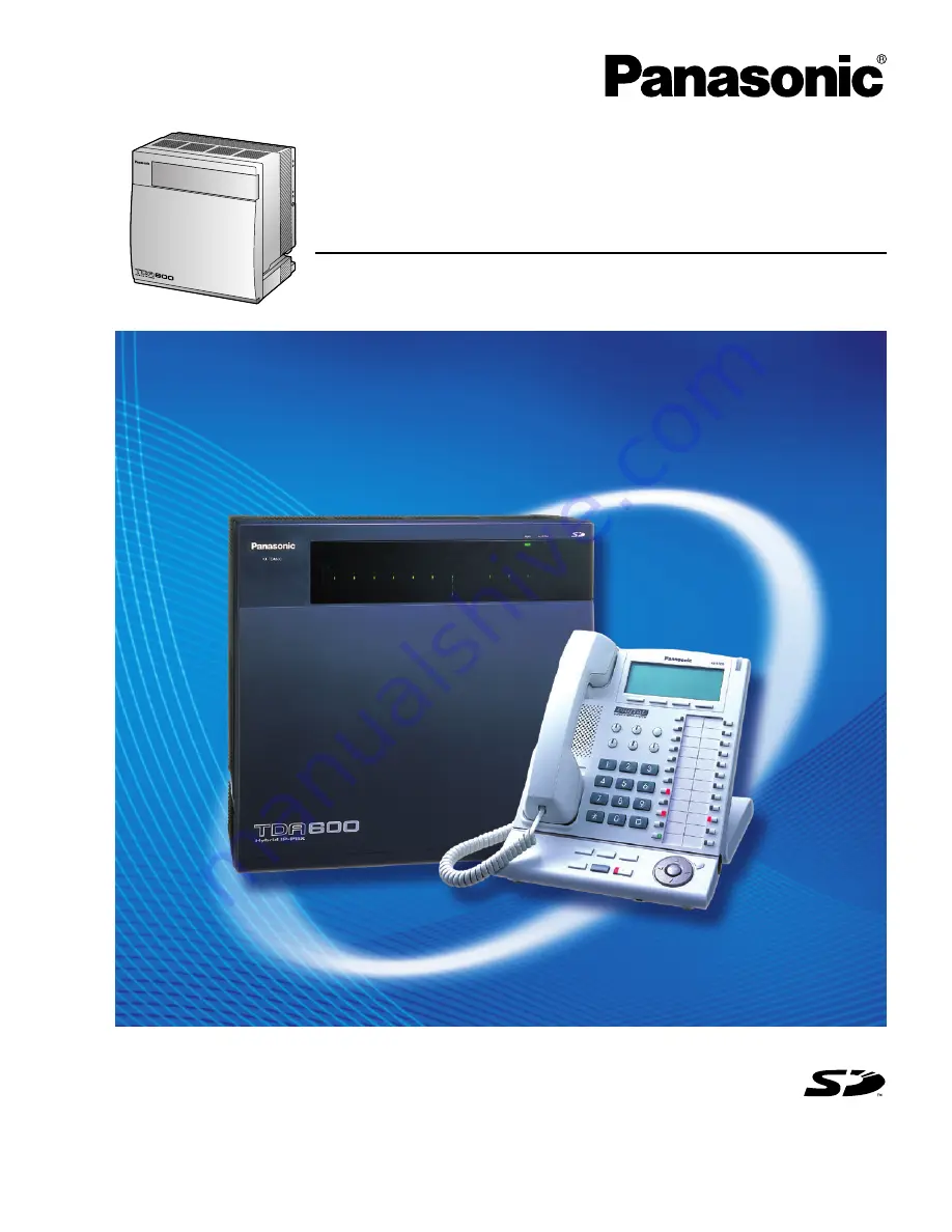
background image

 Model No.    

KX-TDA600

Hybrid IP-PBX

Installation Manual

Thank you for purchasing a Panasonic Hybrid IP-PBX.
Please read this manual carefully before using this product and save this manual for future use.

KX-TDA600: PLMPR Software File Version 3.1000 or later

SD Logo is
a trademark.

Document Version: 2006-07

Summary of Contents for KX-TDA600 - Hybrid IP PBX Control Unit Max. 1008...

Page 1: ...al Thank you for purchasing a Panasonic Hybrid IP PBX Please read this manual carefully before using this product and save this manual for future use KX TDA600 PLMPR Software File Version 3 1000 or later SD Logo is a trademark Document Version 2006 07 ...

Page 2: ...ds KX TDA0187 T 1 Trunk Card T1 KX TDA0193 8 Port Caller ID Card CID8 KX TDA0290 PRI Card PRI23 KX TDA0484 4 Channel VoIP Gateway Card IP GW4E KX TDA0490 16 Channel VoIP Gateway Card IP GW16 KX TDA6181 16 Port Analog Trunk Card ELCOT16 Extension Cards KX TDA0143 4 Cell Station Interface Card CSIF4 KX TDA0144 8 Cell Station Interface Card CSIF8 KX TDA0170 8 Port Digital Hybrid Extension Card DHLC8 ...

Page 3: ...16 Optional SD Memory Card KX TDA6920 SD Memory Card for Software Upgrade to Enhanced Version Power Supply Units PSUs KX TDA0103 L Type Power Supply Unit PSU L KX TDA0104 M Type Power Supply Unit PSU M Cell Stations CSs KX T0141 2 Channel Cell Station Unit Using a DHLC DLC Card PT interface CS for 2 4 GHz Portable Station KX TDA0142 3 Channel Cell Station Unit Using a CSIF Card for 2 4 GHz Portabl...

Page 4: ... equipment e g Add on Key Module USB Module Headset 1 that can be connected to a particular telephone refer to the telephone s manual For other equipment that can be connected to the Hybrid IP PBX refer to 1 2 3 System Connection Diagram Category Model No Description MPR Optional Card KX TDA0105 Memory Expansion Card MEC CO Line Cards KX TDA0180 8 Port Analog Trunk Card LCOT8 KX TDA0181 16 Port An...

Page 5: ...ne telephone SLT Important Notice Prior to connection of this product please verify that the intended operating environment is supported Satisfactory performance cannot be guaranteed for the following interoperability and compatibility with all devices and systems connected to this product proper operation and compatibility with services provided by telecommunications companies over connected netw...

Page 6: ...let please have one installed Do not bypass this safety feature by tampering with the plug 9 Do not allow anything to rest on the power cord Do not locate this product where the power cord may be stepped on or tripped on 10 To reduce the risk of fire or electric shock do not overload wall outlets and extension cords 11 Do not insert objects of any kind into this product through its slots and openi...

Page 7: ...Installation Manual 7 SAVE THESE INSTRUCTIONS ...

Page 8: ...tallation Manual Precaution WARNING DO NOT REMOVE SD MEMORY CARD WHILE POWER IS SUPPLIED TO THE H Y B R I D I P P B X Doing so may cause the Hybrid IP PBX to fail to start when you try to restart the system ...

Page 9: ...Y ONLY BE INSTALLED AND SERVICED BY QUALIFIED SERVICE PERSONNEL IF DAMAGE TO THE UNIT EXPOSES ANY INTERNAL PARTS DISCONNECT THE POWER SUPPLY CORD IMMEDIATELY AND RETURN THE UNIT TO YOUR DEALER UNPLUG ALL INSTALLED SHELVES OF THE SYSTEM FROM THE AC OUTLET IF IT EMITS SMOKE AN ABNORMAL SMELL OR MAKES UNUSUAL NOISE THESE CONDITIONS CAN CAUSE FIRE OR ELECTRIC SHOCK CONFIRM THAT SMOKE HAS STOPPED AND C...

Page 10: ...sswords of 10 numbers or characters be used for maximum protection against unauthorized access For a list of numbers and characters that can be used in system passwords refer to 1 1 2 Entering Characters in the PC Programming Manual 6 If a system password is forgotten it can be found by loading a backup of the system data into a PC and checking the password using the KX TDA600 Maintenance Console ...

Page 11: ... Servicenters for this product are listed in the servicenter directory Consult your certified Panasonic dealer for detailed instructions For Future Reference Please print record and retain the following information for future reference Note The serial number of this product can be found on the label affixed to the unit You should record the model number and the serial number of this unit as a perm...

Page 12: ...stallation Manual the following manuals are available Feature Manual Describes all basic optional and programmable features of the Hybrid IP PBX PC Programming Manual Provides step by step instructions for performing system programming using a PC PT Programming Manual Provides step by step instructions for performing system programming using a PT Operating Manual Provides operating instructions fo...

Page 13: ...t of the product identifier that has the following format US AAAEQ TXXXX The digits represented by are the REN without a decimal point e g 03 is a REN of 0 3 For earlier products the REN is separately shown on the label 3 Incidence of Harm to the Telephone Lines If this equipment causes harm to the telephone network the telephone company will notify you in advance that temporary discontinuance of ...

Page 14: ...correct the interference by one or more of the following measures Reorient or relocate the receiving antenna Increase the separation between the equipment and receiver Connect the equipment into an outlet on a circuit different from that to which the receiver is connected Consult the dealer or an experienced radio TV technician for help CAUTION Any changes or modifications not expressly approved b...

Page 15: ...lp Some wireless telephones operate at frequencies that may cause interference to nearby TVs and VCRs To minimize or prevent such interference the base of the wireless telephone should not be placed near or on top of a TV or VCR If interference is experienced move the wireless telephone further away from the TV or VCR This will often reduce or eliminate interference Operating near 2 4 GHz electric...

Page 16: ... System Tower Type 58 2 2 7 Installation of 4 shelf System Side by side Type 80 2 2 8 Wall Mounting KX TDA600 KX TDA620 96 2 2 9 Installing Replacing the Power Supply Unit 98 2 2 10 Frame Ground Connection 102 2 2 11 Installing Removing the Optional Service Cards 103 2 2 12 Cable Handling 107 2 2 13 Types of Connectors 109 2 2 14 Attaching a Ferrite Core 111 2 2 15 Fastening Amphenol Connector 113...

Page 17: ...ons 165 2 9 3 Digital EXtra Device Port Digital XDP Connection 168 2 9 4 First Party Call Control CTI Connection 170 2 10 Connection of 2 4 GHz Portable Stations 171 2 10 1 Overview 171 2 10 2 Procedure Overview 173 2 10 3 Site Planning 175 2 10 4 Before Site Survey 179 2 10 5 Site Survey 181 2 10 6 After Site Survey 185 2 10 7 Connecting a Cell Station to the Hybrid IP PBX 186 2 10 8 Wall Mountin...

Page 18: ...18 Installation Manual 4 1 Troubleshooting 218 4 1 1 Installation 218 4 1 2 Connection 220 4 1 3 Operation 222 4 1 4 Using the Reset Button 224 4 1 5 Troubleshooting by Error Log 225 Index 227 ...

Page 19: ...Installation Manual 19 Section 1 System Outline This section provides general information on the Hybrid IP PBX including the system capacity and specifications ...

Page 20: ...all call center which can take advantage of several features some of which are highlighted below Queuing When all available extensions in an ICD group are busy additional calls can be placed in a queue as they arrive While calls are waiting in the queue callers can hear background music BGM an outgoing message OGM etc Log in Log out Members of an ICD group can log in to or log out of a group manua...

Page 21: ...per Hybrid port of the Hybrid IP PBX Unlike parallel mode XDP mode allows each telephone to act as an independent extension with its own extension number Digital XDP A DPT can be connected to another DPT that is connected to a DPT port or a Super Hybrid port of the Hybrid IP PBX Similar to XDP mode each DPT acts as an independent extension with its own extension number Portable Station PS Features...

Page 22: ...ing the Hybrid IP PBX To use the basic system install a power supply unit PSU in the PSU Slot and optional service cards in Free Slots To expand to a multiple shelf system you also need to install a BUS M card in the BUS M Card Slot Construction of the Basic Shelf Basic Shelf KX TDA600 EMPR Card Free Slots BUS M Card Slot PSU Slot Basic Shelf KX TDA600 ...

Page 23: ...to the Basic Shelf To use Expansion Shelf connect it to the Basic Shelf and install a power supply unit PSU in the PSU Slot and optional service cards in Free Slots Up to 3 Expansion Shelves can be connected to the Basic Shelf Construction of an Expansion Shelf Expansion Shelf KX TDA620 BUS S Card Expansion Shelf KX TDA620 Free Slots PSU Slot ...

Page 24: ...nded system Basic Shelf 1 Expansion Shelf Expansion Shelf 1 is mounted on the Basic Shelf Note If you are installing a 2 shelf system in an area prone to earthquakes make sure to fix the system to the wall using the wall brackets supplied with an optional Mounting Kit ...

Page 25: ...nstruction Installation Manual 25 3 shelf System Tower Type Expanded system Basic Shelf 2 Expansion Shelves Expansion Shelves 1 and 2 are mounted on the Basic Shelf A Mounting Kit is required for the 3 shelf system ...

Page 26: ...truction 26 Installation Manual 4 shelf System Tower Type Fully expanded system Basic Shelf 3 Expansion Shelves Expansion Shelves 1 to 3 are mounted on the Basic Shelf A Mounting Kit is required for the 4 shelf system ...

Page 27: ...nded system Basic Shelf Expansion Shelf 1 and Expansion Shelf 2 Expansion Shelf 3 in a side by side configuration Expansion Shelf 1 is mounted on the Basic Shelf and Expansion Shelf 3 is mounted on Expansion Shelf 2 Installing the system using base stands supplied with an optional Mounting Kit makes it easy to reinstall shelves in a different place ...

Page 28: ...ce Processing System KX T7636 KX T7633 Remote PC PC Printer Router Private IP Network CO Telephone Company Lines Analog PRI T1 Hybrid IP PBX PC SLT CS PS Wireless Phone Fax Machine PC USB APT DPT ISDN Telephone Amplifier CTI Server PC PC SLT DPT DSS Console DSS Console KX T7600 DPT KX T7600 DPT External Sensor External Relay Device PC IP PT ...

Page 29: ...ne CO Line Analog CO Line Telephone Company CSIF4 KX TDA0143 CSIF8 KX TDA0144 EMPR Installed by default RMT KX TDA0196 EMEC KX TDA6105 DLC16 KX TDA0172 DLC8 KX TDA0171 EMSLC16 KX TDA6175 SLC8 KX TDA0173 EXT CID KX TDA0168 ESLC16 KX TDA6174 OPB3 KX TDA0190 EECHO16 KX TDA6166 MSG4 KX TDA0191 EIO4 KX TDA0164 DPH4 KX TDA0161 IP EXT16 KX TDA0470 IP PT LAN PC KX T7636 KX T7633 DSS Console PT interface C...

Page 30: ...consoles and PT interface CSs with 2 power failure transfer PFT ports KX TDA0171 8 Port Digital Extension Card DLC8 8 port digital extension card for DPTs DSS consoles and PT interface CSs KX TDA0172 16 Port Digital Extension Card DLC16 16 port digital extension card for DPTs DSS consoles and PT interface CSs KX TDA0173 8 Port Single Line Telephone Extension Card SLC8 8 port extension card for SLT...

Page 31: ...nting Expansion Shelves To be installed in the Basic Shelf only KX TDA6111 Bus Master Expansion Card BUS ME Optional shelf expansion card required when mounting Expansion Shelf 2 or 3 To be mounted on the BUS M card installed in the Basic Shelf KX TDA6166 16 Channel Echo Canceller Card EECHO16 16 channel card for echo cancellation during conferences KX TDA6174 16 Port Single Line Telephone Extensi...

Page 32: ...uration 7 years Dialing CO Line Dial Pulse DP 10 pps 20 pps Tone DTMF Dialing Extension Dial Pulse DP 10 pps 20 pps Tone DTMF Dialing Mode Conversion DP DTMF DTMF DP Ring Frequency 20 Hz 25 Hz selectable Central Office Loop Limit 1600 Ω maximum Operating Environment Temperature 0 C to 40 C 32 F to 104 F Humidity 10 to 90 non condensing Conference Call CO Line per shelf From 10 3 party conference c...

Page 33: ...re D1 D2 DSS Console and Add on Key Module 1 pair wire D1 D2 Dimension Basic Shelf 430 mm W 415 mm H 270 mm D 17 1 5 in 16 3 5 in 10 4 5 in Expansion Shelf 430 mm W 415 mm H 270 mm D 17 1 5 in 16 3 5 in 10 4 5 in Weight when fully mounted Basic Shelf Under 16 kg 35 2 lb Expansion Shelf Under 16 kg 35 2 lb 1 If tolerance may be exceeded an Uninterruptible Power Supply UPS is recommended ...

Page 34: ... of 2 DPTs and an SLT Ring Voltage 75 Vrms at 20 Hz 25 Hz depending on the Ringing Load Central Office Loop Limit 1600 Ω maximum Hookswitch Flash Timing Range 24 ms to 2032 ms Door Opener Current Limit 24 V DC 30 V AC 1 A maximum External Relay Current Limit 24 V DC 30 V AC 1 A maximum External Sensor Current Limit Power to the external sensor is provided from the EIO4 card and must be grounded th...

Page 35: ...2 types of optional service cards for installation Cards installed in the slots of the Hybrid IP PBX Cards mounted on other optional service cards Notes Any card that exceeds the capacity of the Hybrid IP PBX will be ignored When the Hybrid IP PBX starts up with an invalid configuration some cards will be ignored Basic System 2 shelf System 3 shelf System 4 shelf System 10 21 32 43 Type Basic Syst...

Page 36: ...in the BUS M Card Slot of the Basic Shelf Card Type Basic System 2 shelf System 3 shelf System 4 shelf System CO Line Card 10 1 1 One T1 or PRI23 card counts as 2 cards 20 1 30 1 40 1 ELCOT16 10 20 30 40 T1 5 10 15 20 PRI23 IP GW4E 10 20 30 40 IP GW16 Extension Card 10 20 30 40 DHLC8 10 20 30 40 DLC8 DLC16 SLC8 ESLC16 EMSLC16 IP EXT16 CSIF4 4 8 12 16 CSIF8 OPB3 4 8 12 16 CTI LINK 2 2 Can be instal...

Page 37: ...d MSG4 4 8 12 16 EIO4 4 8 12 16 BUS ME 1 2 BUS M Card Terminal Equipment Type Basic System 2 shelf System 3 shelf System 4 shelf System Telephone 160 320 480 640 using Digital XDP 288 1 1 Even when Digital XDP is used each shelf supports a maximum of 256 KX T7600 series DPTs 576 1 800 1 960 1 SLT 160 320 480 640 KX T7600 series DPT 256 512 640 640 Other DPT 128 256 384 512 APT 80 160 240 320 IP PT...

Page 38: ...greater than 128 you must install the PSU L If the total load figure is less than 128 but you expect expansion in the future it may be better to install the PSU L instead of the PSU M There is no harm in installing a PSU that is larger than is required for the current configuration Equipment Type Load Figure PT KX T7600 series DPT KX T7600 series DSS console 1 Other DPT Other DSS console 4 APT 4 I...

Page 39: ...alculation Example The total load figure is 136 As this is between 128 and 512 you must install the PSU L Equipment Type Load Figure KX T7600 series DPT 48 units 48 Other DPT 4 units 16 ESLC16 1 card 16 EMSLC16 3 cards 48 VPS 8 ports 8 Total 136 ...

Page 40: ...1 4 Specifications 40 Installation Manual ...

Page 41: ...dures to install the Hybrid IP PBX Detailed instructions for planning the installation site installing the shelves and optional service cards and cabling of peripheral equipment are provided Further information on system expansion and peripheral equipment installation is included ...

Page 42: ...t cold or humid places Temperature range 0 C to 40 C 32 F to 104 F 2 Areas where sulfuric gases may be present such as near thermal springs 3 Areas where shocks or vibrations are frequent or strong 4 High dust areas or places the system may come into contact with water or oil 5 Near devices that generate high frequencies such as sewing machines or electric welders 6 On or near computers telexes or...

Page 43: ... not operate properly disconnect the telephone from the extension line and connect it again or turn off the Hybrid IP PBX using the power switch then turn it on again 8 For safety purposes this unit is equipped with a grounded plug If you do not have a grounded outlet please have one installed Do not bypass this safety feature by tampering with the plug 9 Use twisted pair cable for CO line connect...

Page 44: ...600 Unpack the box and check the items below Supplied Items for an Expansion Shelf KX TDA620 Unpack the box and check the items below Main Unit 1 Metal Bracket 1 Anchor Plug 4 Fan Guard 2 Mini Plug for pager and music source 4 SD Memory Card 1 Screw A 4 Screw B 6 Screw C 2 Main Unit 1 Metal Bracket 1 Anchor Plug 4 Fan Guard 2 Screw A 4 Screw B 6 Screw C 2 ...

Page 45: ... are installing a multiple shelf system in an area prone to earthquakes make sure to fix the system to the wall using the wall brackets When installing the Mounting Kit it is necessary to use the screws A and anchor plugs supplied with the Basic Shelf or Expansion Shelf Wall Bracket Right 2 Wall Bracket Left 2 Base Stand 4 Support Bracket 4 Washer 16 Screw D 8 ...

Page 46: ...Locations Inside View A RUN Indicator B ALARM Indicator C USB Port D RS 232C Port E PSU Slot F Free Slots 1 to 10 from the left G EMPR Card H BUS M Card Slot I Free Slots 1 to 11 from the left J BUS S Card A B F D C A B G E I J H E Expansion Shelf KX TDA620 Basic Shelf KX TDA600 ...

Page 47: ...g the Front Cover Opening the Front Cover 1 Insert a flathead screwdriver into the opening on the left of the screw cover and unlatch the screw cover 2 Turn the screw counterclockwise to loosen 3 Slide the front cover to the right until it stops then lift the front cover Screw Cover ...

Page 48: ...ions on the cover with the receptacles on the shelf Then slide the front cover to the left until it locks 2 Turn the screw clockwise to tighten 3 Secure the screw cover Notes For safety reasons close the front cover and tighten the screw before operating the Hybrid IP PBX Do not forget to tighten the screw before securing the screw cover 1 2 ...

Page 49: ...Guards Fan Guards supplied with the shelf must be attached using the screws C when installing a multiple shelf system mounting the shelf on the wall or installing the shelf near the wall to protect the air vents on the back of the shelf Note If you need to remove the Fan Guard Fan Guards Screw C Screw C ...

Page 50: ... Opening Closing the Front Cover Do not install any optional service cards or a PSU in the shelves before installation Do not block the openings of the shelf Allow space of at least 10 cm 4 in at the sides of the shelf and 20 cm 8 in above the top mounted shelf Make sure that the surface behind the shelf is flat and free of obstacles so that the openings on the back of the shelf will not be blocke...

Page 51: ...h the Basic Shelf to the metal bracket 1 Install 4 anchor plugs on the floor using the metal bracket as a template Fix the metal bracket in place with 4 screws A 2 Lift the Basic Shelf attach it to the metal bracket and slide it backwards until it locks TOP 30 mm 1 3 16 in 8 mm 5 16 in Floor Screw A Metal Bracket Anchor Plug Anchor Plug Hammer Metal Bracket Screw A FRONT TOP 1 2 Metal Bracket ...

Page 52: ...f you are installing a 2 shelf system follow the procedure below Mounting Expansion Shelf 1 For the 2 shelf system attach the metal bracket supplied with the Expansion Shelf 1 to the Basic Shelf first Then mount Expansion Shelf 1 on the Basic Shelf 1 Remove the 4 tabs on the top cover of the Basic Shelf by using a flathead screwdriver as shown below Screw B Basic Shelf ...

Page 53: ... Installation Manual 53 2 Fix the metal bracket to the Basic Shelf with 4 screws B 3 Lift Expansion Shelf 1 attach it to the metal bracket on the Basic Shelf and slide it backwards until it locks TOP Screw B Metal Bracket 1 2 Metal Bracket ...

Page 54: ... Installation of the Hybrid IP PBX 54 Installation Manual 4 Secure Expansion Shelf 1 to the metal bracket with 2 screws B Shelf installation is complete Next it is necessary to connect the shelves Screw B ...

Page 55: ... the BUS S card built in to Expansion Shelf 1 For details about the cards refer to 2 4 1 BUS M Card KX TDA6110 and 2 5 1 BUS S Card Note When installing or removing the BUS M card make sure that the DC power supply is turned off 1 Insert the BUS M card along the guide rails in the BUS M Card Slot the right most slot of the Basic Shelf 2 Push the release lever in the direction of the arrow so that ...

Page 56: ...he BUS M card in place 4 Plug the Bus Cable into the bottom port of the BUS M card in the Basic Shelf Then plug the other end into the BUS S card in Expansion Shelf 1 Note When plugging or unplugging the Bus Cable make sure that the DC power supply is turned off Screws For Expansion Shelf 1 Bus Cable ...

Page 57: ...al 57 5 Attach the noise shield wires of the Bus Cable to the Basic Shelf and Expansion Shelf 1 with the screws of the BUS M card Note When attaching or removing the noise shield wires make sure that the DC power supply is turned off Noise Shield Wire Screw ...

Page 58: ...c Shelf For a 3 or 4 shelf system you need a Mounting Kit which supplies you with the base stands and wall brackets Construction of 3 or 4 shelf System Tower Type 3 shelf System Expansion Shelf 1 Basic Shelf Metal Bracket Metal Bracket Expansion Shelf 3 Expansion Shelf 2 Metal Bracket Metal Bracket Wall Bracket Right Wall Bracket Right Wall Bracket Left Wall Bracket Left 4 shelf System Base Stand ...

Page 59: ...e that the surface behind the shelf is flat and free of obstacles so that the openings on the back of the shelf will not be blocked Make sure that the surface behind the shelf is not made of wood Be careful not to drop the shelf Installing the Basic Shelf To install the Basic Shelf attach the metal bracket supplied with the Basic Shelf to the base stands supplied with the Mounting Kit first Then i...

Page 60: ...2 2 Installation of the Hybrid IP PBX 60 Installation Manual 2 Place the metal bracket on the base stands 3 Attach the metal bracket to the base stands with 4 screws B Metal Bracket Screw B ...

Page 61: ... 61 4 Make 4 holes for anchor plugs on the floor using the measurements indicated here If the direction of the base stands is reversed the measurement must be 443 4 mm 17 7 16 in 510 mm 20 1 16 in Floor Wall 287 mm 11 5 16 in 95 mm 3 3 4 in 382 mm 15 1 16 in ...

Page 62: ...se stands to the floor loosely with 4 screws A This makes it easy to adjust the position of the shelves later 6 Remove the 4 tabs on the top cover of the Basic Shelf by using a flathead screwdriver as shown below Anchor Plug Hammer 30 mm 1 3 16 in 8 mm 5 16 in Base Stand Washer Screw A Floor Anchor Plug Screw A Washer Basic Shelf ...

Page 63: ...IP PBX Installation Manual 63 7 Lift the Basic Shelf attach it to the metal bracket and slide it backwards until it locks 8 Secure the Basic Shelf to the metal bracket with 2 screws B FRONT 1 2 FRONT 1 2 TOP TOP Metal Bracket Screw B ...

Page 64: ...o the Basic Shelf first After mounting Expansion Shelf 1 on the Basic Shelf fix Expansion Shelf 1 to the wall Then mount Expansion Shelf 2 on Expansion Shelf 1 Expansion Shelf 1 1 Fix the metal bracket to the Basic Shelf with 4 screws B 2 Remove the 4 tabs on the top cover of Expansion Shelf 1 by using a flathead screwdriver as shown below TOP Screw B Metal Bracket Expansion Shelf 1 ...

Page 65: ...IP PBX Installation Manual 65 3 Lift Expansion Shelf 1 attach it to the metal bracket on the Basic Shelf and slide it backwards until it locks 4 Secure Expansion Shelf 1 to the metal bracket with 2 screws B 1 2 Metal Bracket Screw B ...

Page 66: ... Hybrid IP PBX 66 Installation Manual Fixing to the Wall 1 Attach the metal bracket to the wall brackets 2 Fix the metal bracket to Expansion Shelf 1 with 4 screws D Wall Bracket Left Wall Bracket Right Metal Bracket Screw D ...

Page 67: ...ve mounting screws into the wall Be careful to avoid touching any metal laths wire laths or metal plates in the wall When installing anchor plugs in the wall be careful not to damage or dirty the shelves Screw A Washer Wall Wall Bracket Left Wall Bracket Right Anchor Plug Hammer Anchor Plug 30 mm 1 3 16 in 413 mm 16 1 4 in 8 mm 5 16 in 892 mm 35 1 8 in 62 mm 2 7 16 in Screw A Washer Wall Bracket ...

Page 68: ...the shelves are leaning slightly to one side move the base stands to adjust the position Since the base stands are attached loosely to the floor it should be possible to adjust the position of the shelves Then tighten the screws connecting the base stands to the floor Floor Wall 95 mm 3 3 4 in 382 mm 15 1 16 in Base Stand ...

Page 69: ...ixed on Expansion Shelf 1 and slide it backwards until it locks 2 Secure Expansion Shelf to the metal bracket 2 with 2 screws B Installation of a 3 shelf system is complete Next it is necessary to connect the shelves If you are installing a 4 shelf system follow the procedure below before connecting the shelves 1 2 Metal Bracket Screw B ...

Page 70: ...Then attach the wall brackets supplied with the Mounting Kit to Expansion Shelf 3 After mounting Expansion Shelf 3 on Expansion Shelf 2 fix Expansion Shelf 3 to the wall Expansion Shelf 3 1 Remove the 4 tabs on the top cover of Expansion Shelf 2 by using a flathead screwdriver as shown below 2 Fix the metal bracket to Expansion Shelf 2 with 4 screws B Expansion Shelf 2 TOP Screw B Metal Bracket ...

Page 71: ...on the top cover of Expansion Shelf 3 by using a flathead screwdriver as shown below 4 Fasten the wall brackets loosely to Expansion Shelf 3 with 4 screws D This makes it easy to adjust the position of the shelves later Expansion Shelf 3 Screw D Wall Bracket Right Wall Bracket Left ...

Page 72: ...2 2 Installation of the Hybrid IP PBX 72 Installation Manual 5 Lift Expansion Shelf 3 attach it to the metal bracket fixed on Expansion Shelf 2 and slide it backwards until it locks 1 2 Metal Bracket ...

Page 73: ...2 2 Installation of the Hybrid IP PBX Installation Manual 73 6 Secure Expansion Shelf 3 to the metal bracket with 2 screws B Screw B ...

Page 74: ...UTION Drive mounting screws into the wall Be careful to avoid touching any metal laths wire laths or metal plates in the wall When installing anchor plugs in the wall be careful not to damage or dirty the shelves 62 mm 2 7 16 in 1731 mm 68 1 8 in 413 mm 16 1 4 in Anchor Plug Wall Screw A Washer Wall Bracket Left Wall Bracket Right Screw A Hammer Anchor Plug Washer Wall Bracket 30 mm 1 3 16 in 8 mm...

Page 75: ... side move Expansion Shelf 3 to adjust the position Since the wall brackets are attached loosely to Expansion Shelf 3 it should be possible to adjust the position of the shelves Then tighten the screws connecting the wall brackets to Expansion Shelf 3 Shelf installation is complete Next it is necessary to connect the shelves Floor Wall Expansion Shelf 3 Wall Bracket ...

Page 76: ...n plug the other end of each Bus Cable into the BUS S card built in to each Expansion Shelf For details about the cards refer to 2 4 1 BUS M Card KX TDA6110 2 4 2 BUS ME Card KX TDA6111 and 2 5 1 BUS S Card Note When installing or removing the BUS M card make sure that the DC power supply is turned off 1 Mount 1 BUS ME card for a 3 shelf system or 2 BUS ME cards for a 4 shelf system on the BUS M c...

Page 77: ...rails in the BUS M Card Slot the right most slot of the Basic Shelf 3 Push the release lever in the direction of the arrow so that the BUS M card engages securely with the connector on the back board 4 Turn the 2 screws clockwise to fix the BUS M card in place Guide Rail Release Lever Back Board Screws ...

Page 78: ...orresponding port of the BUS M card in the Basic Shelf Then plug the other end into the BUS S card in each Expansion Shelf Note When plugging or unplugging the Bus Cables make sure that the DC power supply is turned off Bus Cable For Expansion Shelf 3 For Expansion Shelf 2 For Expansion Shelf 1 ...

Page 79: ... 79 6 Attach the noise shield wires of each Bus Cable to the Basic Shelf and each Expansion Shelf with the screws of the BUS M card Note When attaching or removing the noise shield wires make sure that the DC power supply is turned off Noise Shield Wire Screw ...

Page 80: ...s or a PSU in the shelves before installation Make sure to install the shelves where the Bus Cable supplied with a BUS M card or BUS ME card can reach the shelves Do not block the openings of the shelf Allow space of at least 10 cm 4 in at the sides of the shelf and 20 cm 8 in above the top mounted shelf Make sure that the surface behind the shelf is flat and free of obstacles so that the openings...

Page 81: ...ptional Mounting Kit first Then install the base stands on the floor and fix the Basic Shelf to it To install Expansion Shelf 1 attach the metal bracket supplied with Expansion Shelf 1 to the Basic Shelf Then mount Expansion Shelf 1 on the Basic Shelf Basic Shelf 1 Attach the support brackets to the base stands Note If necessary it is possible to reverse the direction of the base stands as shown b...

Page 82: ...2 2 Installation of the Hybrid IP PBX 82 Installation Manual 2 Place the metal bracket on the base stands 3 Attach the metal bracket to the base stands with 4 screws B Metal Bracket Screw B ...

Page 83: ... 83 4 Make 4 holes for anchor plugs on the floor using the measurements indicated here If the direction of the base stands is reversed the measurement must be 443 4 mm 17 7 16 in 510 mm 20 1 16 in Floor Wall 287 mm 11 5 16 in 95 mm 3 3 4 in 382 mm 15 1 16 in ...

Page 84: ...oles on the floor Then fasten the base stands to the floor with 4 screws A 6 Remove the 4 tabs on the top cover of the Basic Shelf by using a flathead screwdriver as shown below Anchor Plug Hammer 30 mm 1 3 16 in 8 mm 5 16 in Base Stand Washer Screw A Floor Anchor Plug Screw A Washer Basic Shelf ...

Page 85: ...IP PBX Installation Manual 85 7 Lift the Basic Shelf attach it to the metal bracket and slide it backwards until it locks 8 Secure the Basic Shelf to the metal bracket with 2 screws B FRONT 1 2 FRONT 1 2 TOP TOP Metal Bracket Screw B ...

Page 86: ...nstallation Manual Expansion Shelf 1 1 Fix the metal bracket to the Basic Shelf with 4 screws B 2 Remove the 4 tabs on the top cover of Expansion Shelf 1 by using a flathead screwdriver as shown below TOP Screw B Metal Bracket Expansion Shelf 1 ...

Page 87: ...loosely to Expansion Shelf 1 with 4 screws D This makes it easy to adjust the position of the shelves later 4 Lift Expansion Shelf 1 attach it to the metal bracket fixed on the Basic Shelf and slide it backwards until it locks Screw D Wall Bracket Right Wall Bracket Left 1 2 Metal Bracket ...

Page 88: ...2 2 Installation of the Hybrid IP PBX 88 Installation Manual 5 Secure Expansion Shelf 1 to the metal bracket with 2 screws B Screw B ...

Page 89: ...AUTION Drive mounting screws into the wall Be careful to avoid touching any metal laths wire laths or metal plates in the wall When installing anchor plugs in the wall be careful not to damage or dirty the shelves Screw A Washer Wall Wall Bracket Left Wall Bracket Right Anchor Plug Hammer Anchor Plug 30 mm 1 3 16 in 413 mm 16 1 4 in 8 mm 5 16 in 892 mm 35 1 8 in 62 mm 2 7 16 in Screw A Washer Wall...

Page 90: ...o adjust the position Since the base stands are attached loosely to the floor it should be possible to adjust the position of the shelves Then tighten the screws connecting the base stands to the floor Installation of the first 2 shelves is complete Next install Expansion Shelves 2 and 3 next to the Basic Shelf and Expansion Shelf 1 Floor Wall 95 mm 3 3 4 in 382 mm 15 1 16 in Base Stand ...

Page 91: ...helf 1 for Expansion Shelves 2 and 3 Expansion Shelves 2 and 3 must be connected to the Basic Shelf using Bus Cables Therefore make sure that Expansion Shelves 2 and 3 are installed so that the Bus Cables can reach the Basic Shelf Shelf installation is complete Next it is necessary to connect the shelves Basic Shelf and Expansion Shelf 1 Expansion Shelves 2 and 3 ...

Page 92: ... slot of the BUS M card Then plug the other end of each Bus Cable into the BUS S card built in to each Expansion Shelf For details about the cards refer to 2 4 1 BUS M Card KX TDA6110 2 4 2 BUS ME Card KX TDA6111 and 2 5 1 BUS S Card Note When installing or removing the BUS M card make sure that the DC power supply is turned off 1 Mount 2 BUS ME cards on the BUS M card as shown below inside BUS M ...

Page 93: ...rails in the BUS M Card Slot the right most slot of the Basic Shelf 3 Push the release lever in the direction of the arrow so that the BUS M card engages securely with the connector on the back board 4 Turn the 2 screws clockwise to fix the BUS M card in place Guide Rail Release Lever Back Board Screws ...

Page 94: ...orresponding port of the BUS M card in the Basic Shelf Then plug the other end into the BUS S card in each Expansion Shelf Note When plugging or unplugging the Bus Cables make sure that the DC power supply is turned off For Expansion Shelf 3 For Expansion Shelf 2 For Expansion Shelf 1 Bus Cable ...

Page 95: ... 95 6 Attach the noise shield wires of each Bus Cable to the Basic Shelf and each Expansion Shelf with the screws of the BUS M card Note When attaching or removing the noise shield wires make sure that the DC power supply is turned off Noise Shield Wire Screw ...

Page 96: ...sing the Front Cover Do not install any optional service cards or a PSU in the shelves before installation Do not block the openings of the shelf Allow space of at least 20 cm 8 in above and 10 cm 4 in at the sides of the shelf Make sure that the surface behind the shelf is flat and free of obstacles so that the openings on the back of the shelf will not be blocked Make sure that the surface behin...

Page 97: ...e other end of each Bus Cable into the BUS S card built in to each Expansion Shelf For a 2 shelf System Basic Shelf 1 Expansion Shelf It is necessary to install an optional BUS M card in the Basic Shelf For how to connect the shelves refer to Connecting Shelves in 2 2 5 Installation of Basic System or 2 shelf System Floor Standing For a 3 or 4 shelf System Basic Shelf 2 or 3 Expansion Shelves It i...

Page 98: ...s provided with each PSU When installing or replacing a PSU basic safety precautions should always be followed to reduce the risk of fire electric shock and injury to persons including the following 1 Never install or replace a PSU during a lightning storm 2 Never install or replace a PSU in wet locations 3 Never install or replace a PSU unless at least 20 s has elapsed after the AC supply is disc...

Page 99: ...the main unit and PSU To discharge static electricity touch ground or wear a grounding strap The following procedures are for installing or replacing a PSU only Do not replace or remove the PSU for any other purpose Installing the Power Supply Unit 1 Insert the PSU along the guide rails CAUTION For safety reasons do not touch parts in the PSU Guide Rail ...

Page 100: ...in the direction of the arrow so that the PSU engages securely with the connector on the back board 3 Turn the 4 screws clockwise in the order indicated by the numbers 1 to 4 to fix the PSU Replacing the Power Supply Unit 1 Unplug the AC power cord Release Lever Back Board 1 3 2 4 Screws ...

Page 101: ...n the 4 screws counterclockwise to loosen them 3 Pull the release lever in the direction of the arrow to disconnect the PSU from the back board 4 Replace the PSU 5 Follow the steps in Installing the Power Supply Unit Screws Release Lever Back Board Current PSU New PSU ...

Page 102: ...a possible reading of up to 250 V AC 2 Connect the meter probes between the 2 main AC voltage points on the wall outlet The reading obtained should be 108 V AC to 132 V AC 3 Move one of the meter probes to the 3rd prong terminal GND Either the same reading or a reading of 0 volt should be obtained 4 If a reading of 0 volt at one terminal and a reading of 108 V AC to 132 V AC at the other terminal ...

Page 103: ... in the main unit and on the optional service cards To discharge static electricity touch ground or wear a grounding strap Note The optional service cards can be installed or removed while the DC power is supplied However when installing or removing the EMPR card BUS M card or BUS S card the DC power supply must be turned off Installing Optional Service Cards 1 Insert the card along the guide rail...

Page 104: ...own below push the release lever in the direction of the arrow so that the card engages securely with the connector on the back board 3 Turn the 2 screws clockwise to fix the card in place Note Make sure the screws are tightened to ground the card securely Release Lever Back Board Screws ...

Page 105: ... Installation Manual 105 Covering the Blank Slots Be sure to cover each slot in which no optional service card is installed by using a Blank Slot Cover CAUTION Failure to install the Blank Slot Cover may cause electromagnetic interference ...

Page 106: ...l Removing the Optional Service Cards 1 Turn the 2 screws counterclockwise to loosen them 2 Pull the release lever in the direction of the arrow to disconnect the card from the back board Pull the card from the shelf to remove it Screws Release Lever Back Board ...

Page 107: ... 12 Cable Handling Note For safety reasons do not stretch bend or pinch the AC power cord Cable Handling for Each Shelf When cables are connected to the shelf run the cables to either the right or the left and then towards the back of the shelf as shown below 3 4 1 2 ...

Page 108: ...f the Hybrid IP PBX 108 Installation Manual Cable Handling for Connected Shelves When running connected cables towards the back of the shelves make sure not to block the opening of each Fan Guard as shown below Fan Guard ...

Page 109: ...X TDA0143 CSIF8 KX TDA0144 T1 KX TDA0187 PRI23 KX TDA0290 CTI LINK KX TDA0410 IP EXT16 KX TDA0470 IP GW4E KX TDA0484 IP GW16 KX TDA0490 Shielded twisted pair cable DHLC8 KX TDA0170 DLC8 KX TDA0171 DLC16 KX TDA0172 SLC8 KX TDA0173 ESLC16 KX TDA6174 EMSLC16 KX TDA6175 ELCOT16 KX TDA6181 DPH4 KX TDA0161 EIO4 KX TDA0164 Basic Shelf KX TDA600 RJ11 1 4 RJ45 8 1 Amphenol Type A Type B 50 25 26 1 10 pin T...

Page 110: ...2 2 Installation of the Hybrid IP PBX 110 Installation Manual EMPR EMPR Connector Type Pin Number Used for USB 2 1 3 4 Mini Plug 2 4 ...

Page 111: ...nector The ferrite core is included with the card When connecting an IP GW16 IP EXT16 card Wrap the cable once around the ferrite core then close the case of the ferrite core Attach the ferrite core 5 cm 1 15 16 in away from the connector When connecting an extension card Pass the cable through the ferrite core then close the case of the ferrite core Attach the ferrite core 3 cm 1 3 16 in away fro...

Page 112: ...2 2 Installation of the Hybrid IP PBX 112 Installation Manual If you need to open the ferrite core use a flathead screwdriver to unlatch the case of the ferrite core ...

Page 113: ...To connect an Amphenol connector use the spring latch or screw to fix the upper part and use Velcro tape to fix the lower part of the connector Type A Spring Latch Velcro Tape Type B Screw Velcro Tape Velcro Tape Velcro Tape 2 1 2 2 1 Spring Latch 1 Spring Latch Remove the screw on the optional service card Insert the screw included with the Amphenol or optional service card ...

Page 114: ...B TB 3 RC D2C RC RC 28 TC D1C TC TC 4 RD RB D2D RD RD RB 29 TD TB D1D TD TD TB 5 RE D2B D2B D2E RE RE 30 TE D1B D1B D1E TE TE 6 RF D2F RF RF 31 TF D1F TF TF 7 RG RC D2G RG RG RC 32 TG TC D1G TG TG TC 8 RH D2C D2C D2H RH RH 33 TH D1C D1C D1H TH TH 9 RI D2I RI RI 34 TI D1I TI TI 10 RJ RD D2J RJ RJ RD 35 TJ TD D1J TJ TJ TD 11 RK D2D D2D D2K RK RK 36 TK D1D D1D D1K TK TK 12 RL D2L RL RL 37 TL D1L TL T...

Page 115: ...ed equipment To protect the system from electrical surges we strongly recommend connecting the system to a surge protector that meets the following specifications Surge arrestor type 3 electrode arrestor DC spark over voltage 230 V Maximum peak current at least 10 kA Additionally proper grounding is very important for the protection of the system refer to 2 2 10 Frame Ground Connection Many countr...

Page 116: ...round b Use a conduit to protect the wire Note The surge protector for an extension and CS is different from that for a CO line Installation of a Grounding Rod CS SLT PT Main Building CO Line CO Line Extn Extn Extn Extension Line Ground Another Building Extn Extn Surge Protector Terminal Board Surge Protector SLT PT Hybrid IP PBX CS CO Line Hybrid IP PBX Grounding Wire Grounding Rod Underground Su...

Page 117: ...ury the grounding rod near the protector The grounding wire should be as short as possible 3 The grounding wire should run straight to the grounding rod Do not run the wire around other objects 4 Bury the grounding rod at least 50 cm 20 in underground Notes The above figures are recommendations only The length of grounding rod and the required depth depend on the composition of the soil ...

Page 118: ...pherals For details about System Initialize Switch refer to 2 14 1 Starting the Hybrid IP PBX For details about Reset Button refer to 4 1 4 Using the Reset Button CAUTION Use only the SD Memory Card included with the Hybrid IP PBX or a Panasonic optional upgrade SD Memory Card The SD Memory Card contains software for all the processes of the Hybrid IP PBX and all the customer data The SD Memory Ca...

Page 119: ...CARD THERE IS A RISK OF EXPLOSION IF THE BATTERY IS REPLACED WITH THE INCORRECT TYPE DISPOSE OF USED BATTERIES ACCORDING TO THE MANUFACTURER S INSTRUCTIONS LED Indications Indication Color Description BATT ALARM Red Battery alarm indication OFF Normal ON Alarm SD ACCESS Green SD memory card status ON Accessing ...

Page 120: ...MEC Card KX TDA6105 Function Memory expansion card to increase system data storage space and double the number of PSs To be mounted on the EMPR card Accessories and User supplied Items Accessories included Screws 2 User supplied not included none inside EMEC Card Screw EMPR Card ...

Page 121: ...2 3 3 RMT Card KX TDA0196 Function Analog modem card for remote communication with the Hybrid IP PBX V90 support To be mounted on the EMPR card Accessories and User supplied Items Accessories included Screws 2 User supplied not included none inside RMT Card Screw EMPR Card ...

Page 122: ...cessories included Bus Cable 1 User supplied not included none LED Indications Indication Color Description CARD STATUS Green Card status indication OFF Starting up Green ON Normal LINK3 Green Link status indication for Expansion Shelf 3 OFF Connection error ON Normal connection LINK2 Green Link status indication for Expansion Shelf 2 OFF Connection error ON Normal connection LINK1 Green Link stat...

Page 123: ...X TDA6111 Function Optional shelf expansion card required when mounting Expansion Shelf 2 or 3 To be mounted on the BUS M card installed in the Basic Shelf Accessories and User supplied Items Accessories included Bus Cable 1 Screws 2 User supplied not included none inside BUS ME Card BUS M Card Screw ...

Page 124: ...ic Shelf CAUTION A LITHIUM BATTERY IS USED IN THE BUS S CARD THERE IS A RISK OF EXPLOSION IF THE BATTERY IS REPLACED WITH THE INCORRECT TYPE DISPOSE OF USED BATTERIES ACCORDING TO THE MANUFACTURER S INSTRUCTIONS LED Indications Indication Color Description CARD STATUS Green Red Card status indication Green ON Normal Red ON Fault includes reset Red Flashing 60 times per minute Out of Service LED Bu...

Page 125: ...OT16 card refer to 2 6 2 CID8 Card KX TDA0193 Accessories and User supplied Items Accessories included Screws 2 User supplied not included Amphenol connector Notes To connect the Amphenol connector refer to 2 2 15 Fastening Amphenol Connector For details about power failure transfer refer to 2 13 1 Power Failure Connections To confirm the CO line connection refer to Confirming the CO Line Connecti...

Page 126: ...ort 8 33 TH Tip port 8 9 RI Ring port 9 34 TI Tip port 9 10 RJ Ring port 10 35 TJ Tip port 10 11 RK Ring port 11 36 TK Tip port 11 12 RL Ring port 12 37 TL Tip port 12 13 RM Ring port 13 38 TM Tip port 13 14 RN Ring port 14 39 TN Tip port 14 15 RO Ring port 15 40 TO Tip port 15 16 RP Ring port 16 41 TP Tip port 16 17 25 Reserved 42 50 Reserved Indication Color Description CARD STATUS Green Red Car...

Page 127: ... Caller ID DTMF To be mounted on the ELCOT16 card Accessories and User supplied Items Accessories included Screws 2 User supplied not included none Switch Settings on ELCOT16 card Switch Type Usage and Status Definition Port Setting DIP Keep all DIP switches at default ON positions Do not change the positions of these switches SW1 OFF ON ON OFF SW2 CID8 Card inside Screw ...

Page 128: ...e CO line through NT1 do not connect to the CO line directly T1 Card must be installed behind an FCC registered and UL or CSA NRTL listed CSU To confirm the CO line connection refer to Confirming the CO Line Connection in 2 14 1 Starting the Hybrid IP PBX CAUTION T1 ports are SELV ports and should only be connected to SELV services Switch Settings Switch Type Usage and Status Definition A B Slide ...

Page 129: ...ll ports are idle Green Flashing 60 times per minute Normal a port is in use Red ON Fault includes reset Red Flashing 60 times per minute Out of Service SYNC ERR Red Non synchronization status indication OFF Normal ON Out of synchronization RAI Red RAI signal status indication OFF Normal ON Alarm Clock Slave Flashing 60 times per minute Alarm Clock Master AIS Red AIS status indication OFF Normal O...

Page 130: ...45 connector Notes Connect this optional service card to the CO line through an NT1 do not connect to the U interface of the CO line directly To confirm the CO line connection refer to Confirming the CO Line Connection in 2 14 1 Starting the Hybrid IP PBX CAUTION PRI ports are SELV ports and should only be connected to SELV services Switch Settings Switch Type Usage and Status Definition A B Slide...

Page 131: ...mes per minute Normal a port is in use Red ON Fault includes reset Red Flashing 60 times per minute Out of Service SYNC ERR Red Non synchronization status indication OFF Normal ON Out of synchronization RAI Red RAI signal status indication OFF Normal ON Alarm Clock Slave Flashing 60 times per minute Alarm Clock Master AIS Red AIS status indication OFF Normal ON Alarm SYNC Green Synchronization sta...

Page 132: ...he IP GW4E card occupies the space of only 1 free slot when it is installed in the Hybrid IP PBX For programming instructions and other information about the IP GW4E card refer to the documentation for the IP GW4E card To program the IP GW4E card use the web programming designed for the IP GW4E card To confirm the CO line connection refer to Confirming the CO Line Connection in 2 14 1 Starting the...

Page 133: ... times per minute Out of Service ONLINE Green On line status indication ON On line mode OFF Off line mode Flashing Maintenance mode Note If the LINK indicator is OFF the ONLINE indicator will also be OFF ALARM Red Alarm indication OFF Normal ON Alarm VoIP BUSY Green VoIP H 323 process indication OFF VoIP process inactive ON VoIP process active LINK Green Link status indication OFF Connection error...

Page 134: ...connecting the RJ45 connector attach the included ferrite core Refer to 2 2 14 Attaching a Ferrite Core For programming instructions and other information about the IP GW16 card refer to the documentation for the IP GW16 card To program the IP GW16 card use the web programming designed for the IP GW16 card To confirm the CO line connection refer to Confirming the CO Line Connection in 2 14 1 Start...

Page 135: ... times per minute Out of Service ONLINE Green On line status indication ON On line mode OFF Off line mode Flashing Maintenance mode Note If the LINK indicator is OFF the ONLINE indicator will also be OFF ALARM Red Alarm indication OFF Normal ON Alarm VoIP BUSY Green VoIP H 323 process indication OFF VoIP process inactive ON VoIP process active LINK Green Link status indication OFF Connection error...

Page 136: ...Items Accessories included none User supplied not included RJ45 connector Notes LINE 5 to LINE 8 are for CSIF8 card only When using the CSIF4 card please note that the Hybrid IP PBX software will recognize the CSIF4 card as the CSIF8 card As a result 8 cell stations may appear to be available however only 4 cell stations are supported by the CSIF4 card For details about connecting the CS refer to ...

Page 137: ...CSIF4 for unused ports or unavailable ports respectively for the following reasons a you will be able to easily distinguish installed CSs b you will be able to know which CSIF card has been installed CSIF4 or CSIF8 Example When the CSIF4 card has been installed 1 Pin Assignments RJ45 Connector 1 The contents and design of the software are subject to change without notice No Signal Name Function 1 ...

Page 138: ... Indications Indication Color Description CARD STATUS Green Red Card status indication OFF Power Off Green ON Normal all ports are idle Green Flashing 60 times per minute Normal a port is in use Red ON Fault includes reset Red Flashing 60 times per minute Out of Service ...

Page 139: ...er PFT ports Accessories and User supplied Items Accessories included Screws 2 Ferrite core 1 User supplied not included Amphenol connector Notes Attach the included ferrite core to the cable Refer to 2 2 14 Attaching a Ferrite Core To connect the Amphenol connector refer to 2 2 15 Fastening Amphenol Connector For details about power failure transfer refer to 2 13 1 Power Failure Connections LED A...

Page 140: ...PT Data port 3 High 9 Reserved 34 Reserved 10 RD SLT Ring port 4 35 TD SLT Tip port 4 11 D2D PT Data port 4 Low 36 D1D PT Data port 4 High 12 Reserved 37 Reserved 13 RE SLT Ring port 5 38 TE SLT Tip port 5 14 D2E PT Data port 5 Low 39 D1E PT Data port 5 High 15 Reserved 40 Reserved 16 RF SLT Ring port 6 41 TF SLT Tip port 6 17 D2F PT Data port 6 Low 42 D1F PT Data port 6 High 18 Reserved 43 Reserv...

Page 141: ...TUS Green Orange Red Card status indication OFF Power Off Green ON Normal all ports are idle Green Flashing 60 times per minute Normal a port is in use Orange Flashing Detection of PT interface CS connection when starting up the PT interface CS Red ON Fault includes reset Red Flashing 60 times per minute Out of Service ...

Page 142: ...oles and PT interface CSs Accessories and User supplied Items Accessories included Screws 2 Ferrite core 1 User supplied not included Amphenol connector Notes Attach the included ferrite core to the cable Refer to 2 2 14 Attaching a Ferrite Core To connect the Amphenol connector refer to 2 2 15 Fastening Amphenol Connector LED Amphenol To extensions ...

Page 143: ...served 14 D2E Data port 5 Low 39 D1E Data port 5 High 15 16 Reserved 40 41 Reserved 17 D2F Data port 6 Low 42 D1F Data port 6 High 18 19 Reserved 43 44 Reserved 20 D2G Data port 7 Low 45 D1G Data port 7 High 21 22 Reserved 46 47 Reserved 23 D2H Data port 8 Low 48 D1H Data port 8 High 24 25 Reserved 49 50 Reserved Indication Color Description CARD STATUS Green Orange Red Card status indication OFF ...

Page 144: ...soles and PT interface CSs Accessories and User supplied Items Accessories included Screws 2 Ferrite core 1 User supplied not included Amphenol connector Notes Attach the included ferrite core to the cable Refer to 2 2 14 Attaching a Ferrite Core To connect the Amphenol connector refer to 2 2 15 Fastening Amphenol Connector LED Amphenol To extensions ...

Page 145: ...1I Data port 9 High 10 D2J Data port 10 Low 35 D1J Data port 10 High 11 D2K Data port 11 Low 36 D1K Data port 11 High 12 D2L Data port 12 Low 37 D1L Data port 12 High 13 D2M Data port 13 Low 38 D1M Data port 13 High 14 D2N Data port 14 Low 39 D1N Data port 14 High 15 D2O Data port 15 Low 40 D1O Data port 15 High 16 D2P Data port 16 Low 41 D1P Data port 16 High 17 25 Reserved 42 50 Reserved Indicat...

Page 146: ...ser supplied Items Accessories included Screws 2 Ferrite core 1 User supplied not included Amphenol connector Notes Attach the included ferrite core to the cable Refer to 2 2 14 Attaching a Ferrite Core To connect the Amphenol connector refer to 2 2 15 Fastening Amphenol Connector For details about power failure transfer refer to 2 13 1 Power Failure Connections LED Amphenol To extensions ...

Page 147: ... TD Tip port 4 11 12 Reserved 36 37 Reserved 13 RE Ring port 5 38 TE Tip port 5 14 15 Reserved 39 40 Reserved 16 RF Ring port 6 41 TF Tip port 6 17 18 Reserved 43 44 Reserved 19 RG Ring port 7 44 TG Tip port 7 20 21 Reserved 45 46 Reserved 22 RH Ring port 8 47 TH Tip port 8 23 25 Reserved 48 50 Reserved Indication Color Description CARD STATUS Green Red Card status indication OFF Power Off Green O...

Page 148: ... Manual 2 7 6 EXT CID Card KX TDA0168 Function Sends Caller ID signals to extension ports To be mounted on the SLC8 card only Accessories and User supplied Items Accessories included Screws 2 User supplied not included none EXT CID Card Screw SLC8 Card inside ...

Page 149: ...to the EMSLC16 card Attach the included ferrite core to the cable Refer to 2 2 14 Attaching a Ferrite Core To connect the Amphenol connector refer to 2 2 15 Fastening Amphenol Connector For details about power failure transfer refer to 2 13 1 Power Failure Connections ESLC16 16 port extension card for SLTs with 4 power failure transfer PFT ports EMSLC16 16 port extension card for SLTs with Message...

Page 150: ...port 8 33 TH Tip port 8 9 RI Ring port 9 34 TI Tip port 9 10 RJ Ring port 10 35 TJ Tip port 10 11 RK Ring port 11 36 TK Tip port 11 12 RL Ring port 12 37 TL Tip port 12 13 RM Ring port 13 38 TM Tip port 13 14 RN Ring port 14 39 TN Tip port 14 15 RO Ring port 15 40 TO Tip port 15 16 RP Ring port 16 41 TP Tip port 16 17 25 Reserved 42 50 Reserved Indication Color Description CARD STATUS Green Red Ca...

Page 151: ...d not included RJ45 connector Notes The maximum length of the cable to be connected to this optional service card is 100 m 328 ft When connecting the RJ45 connector attach the included ferrite core Refer to 2 2 14 Attaching a Ferrite Core Pin Assignments RJ45 Connector 10BASE T 100BASE TX No Signal Name Input I Output O Function 1 TPO O Transmit data 2 TPO O Transmit data 3 TPI I Receive data 4 5 ...

Page 152: ... ONLINE Green On line status indication ON At least one port is in use an IP PT is connected OFF No ports are in use no IP PTs are connected Note If the LINK indicator is OFF the ONLINE indicator will also be OFF ALARM Red Alarm indication OFF Normal ON Alarm VoIP BUSY Green Panasonic proprietary VoIP protocol process indication OFF VoIP process inactive ON VoIP process active LINK Green Link stat...

Page 153: ...ded none User supplied not included none CAUTION A LITHIUM BATTERY IS USED IN OPB3 CARD THERE IS A RISK OF EXPLOSION IF THE BATTERY IS REPLACED WITH THE INCORRECT TYPE DISPOSE OF USED BATTERIES ACCORDING TO THE MANUFACTURER S INSTRUCTIONS LED Indications Indication Color Description CARD STATUS Green Red Card status indication OFF Power Off Green ON Normal all ports are idle Green Flashing 60 time...

Page 154: ...supplied Items Accessories included Screws 3 10 pin terminal block 1 8 pin terminal block 1 User supplied not included Copper wire Note For details about connection to doorphones and door openers refer to 2 11 1 Connection of Doorphones Door Openers External Sensors and External Relays Screw DPH4 Card OPB3 Card Fully insert the connectors through the panel openings To door openers To doorphones 10...

Page 155: ...ive 3 DP3 Doorphone 3 transmit 4 com3 Doorphone 3 receive 5 DP2 Doorphone 2 transmit 6 com2 Doorphone 2 receive 7 DP1 Doorphone 1 transmit 8 com1 Doorphone 1 receive No Signal Name Function 1 2 Reserved 3 OP4b Door opener 4 4 OP4a Door opener 4 com 5 OP3b Door opener 3 6 OP3a Door opener 3 com 7 OP2b Door opener 2 8 OP2a Door opener 2 com 9 OP1b Door opener 1 10 OP1a Door opener 1 com 8 1 10 1 ...

Page 156: ...ories included Screws 3 10 pin terminal block 1 8 pin terminal block 1 User supplied not included Copper wire Note For details about connection to external sensors and external relays refer to 2 11 1 Connection of Doorphones Door Openers External Sensors and External Relays Screw EIO4 Card OPB3 Card Fully insert the connectors through the panel openings To external relays To external sensors 10 pi...

Page 157: ...ction 1 C4b Control 4 2 C4a Control 4 com 3 C3b Control 3 4 C3a Control 3 com 5 C2b Control 2 6 C2a Control 2 com 7 C1b Control 1 8 C1a Control 1 com No Signal Name Function 1 2 Reserved 3 OP4b Opener 4 4 OP4a Opener 4 com 5 OP3b Opener 3 6 OP3a Opener 3 com 7 OP2b Opener 2 8 OP2a Opener 2 com 9 OP1b Opener 1 10 OP1a Opener 1 com 8 1 10 1 ...

Page 158: ...EIO4 card as indicated in the diagram below A pair of sensor and common lines are connected to the EIO4 card for each external sensor The Hybrid IP PBX detects input from the sensor when the signal is under 100 Ω Connection Diagram External Relay Current Limit 24 V DC 30 V AC 1 A maximum External Sensor sensor common I O EIO4 OPB3 Hybrid IP PBX 5V 5V 10K 33 33 4 7K 4 7K ...

Page 159: ...stallation Manual 159 2 8 4 MSG4 Card KX TDA0191 Function 4 channel message card To be mounted on the OPB3 card Accessories and User supplied Items Accessories included Screws 3 User supplied not included none Screw MSG4 Card OPB3 Card inside ...

Page 160: ...to 8 parties install an EECHO16 card and enable echo cancellation for conferences using the KX TDA600 Maintenance Console For details refer to Echo Cancel Conference in 2 8 17 2 9 System Options of the PC Programming Manual LED Indications Indication Color Description CARD STATUS Green Red Card status indication OFF Power Off Green ON Normal all ports are idle Green Flashing 60 times per minute No...

Page 161: ... to this optional service card is 100 m 328 ft This optional service card can be connected to PCs on a LAN via a CTI server to provide third party call control CTI The operating system of the PC or CTI server required for third party call control depends on your CTI application software For details refer to the manual for your CTI application software Pin Assignments RJ45 Connector 10BASE T No Sig...

Page 162: ...ations Indication Color Description CARD STATUS Green Red Card status indication OFF Power Off Green ON Normal Red ON Fault includes reset Red Flashing 60 times per minute Out of Service LINK STATUS Green Link status indication Flashing In communication ON Linked normally ...

Page 163: ...ster DPT on the Digital XDP connection SLT Other PT DPT APT and DSS Console KX T7600 Series DPT PT interface CS Cable Maximum Distance 26 AWG 500 m 1640 ft 24 AWG 720 m 2362 ft 22 AWG 830 m 2723 ft CAT 5 720 m 2362 ft Cable Maximum Distance 26 AWG 140 m 459 ft 24 AWG 229 m 751 ft 22 AWG 360 m 1181 ft CAT 5 229 m 751 ft Cable Maximum Distance 26 AWG 698 m 2289 ft 24 AWG 1128 m 3700 ft 22 AWG 1798 m...

Page 164: ...2 9 Connection of Extensions 164 Installation Manual indicates that the extension card supports the terminal PT interface CS DPT APT DSS Console SLT DHLC8 Card EMSLC16 ESLC16 SLC8 Cards DLC16 DLC8 Cards ...

Page 165: ...modem PC can be connected in parallel with an APT or a DPT With APT For parallel connection eXtra Device Port XDP mode must be disabled for that port through system programming Refer to 1 13 2 Paralleled Telephone and 1 5 7 Extension Port Configuration in the Feature Manual for further information To DHLC8 card 4 conductor wiring cord Connect pins T R D1 and D2 2 conductor wiring cord Connect pins...

Page 166: ...lephone and 1 5 7 Extension Port Configuration in the Feature Manual for further information Using a Modular T Adaptor Using an EXtra Device Port With KX T7600 Series DPT To DHLC8 card SLT DPT Modular T Adaptor 4 conductor wiring cord Connect pins D1 and D2 2 conductor wiring cord Connect pins T and R To DHLC8 card DPT SLT To DHLC8 card To SLT 2 conductor wiring cord Connect pins T and R 4 conduct...

Page 167: ...Extensions Installation Manual 167 With Other DPT To DHLC8 card DPT SLT To DHLC8 card To SLT 2 conductor wiring cord Connect pins T and R 4 conductor wiring cord Connect pins T R D1 and D2 TO TEL TO EMSS or TO MAIN UNIT ...

Page 168: ...through system programming parallel connection is not possible Refer to 1 13 2 Paralleled Telephone and 1 5 7 Extension Port Configuration in the Feature Manual for further information With KX T7600 Series DPT Using a Modular T Adaptor To DLC8 DLC16 card To DHLC8 card for connection of SLT 4 conductor wiring cord Connect pins D1 and D2 Slave DPT SLT Master DPT Modular T Adaptor 4 conductor wiring ...

Page 169: ...ord Connect pins T and R 4 conductor wiring cord Connect pins T R D1 and D2 Slave DPT Master DPT To SLT TO MAIN UNIT PABX TO TEL TO TEL TO MAIN UNIT PABX Back View of DPTs To DLC8 DLC16 card To DHLC8 card for connection of SLT To DLC8 DLC16 card To DHLC8 card for connection of SLT Cable Maximum Distance 26 AWG 30 m 98 ft 24 AWG 50 m 164 ft 22 AWG 60 m 196 ft CAT 5 50 m 164 ft ...

Page 170: ...ected to the KX T7633 T7636 DPT Note The operating system of the PC required for first party call control depends on your CTI application software For details refer to the manual for your CTI application software Notes The maximum length of the USB cable is 3 m 9 ft 10 in USB Modules must not be connected to DPTs in the Digital XDP connection In a Digital XDP connection the PC cannot be used If a ...

Page 171: ...ore details about the PS refer to the PS Operating Instructions CAUTION The CS should be kept free of dust moisture high temperature more than 40 C 104 F low temperature less than 0 C 32 F and vibration and should not be exposed to direct sunlight The CS should not be placed outdoors use indoors The CS should not be placed near high voltage equipment The CS should not be placed on a metal object S...

Page 172: ...istance between the CSs when site planning Please consult a certified dealer for details However the required distance between CSs may vary depending on the environment of the installation site and conditions in which the wireless system is used Conduct the site survey to determine the appropriate distance ...

Page 173: ...nned Notes Install at least 2 m 6 ft 7 in above the floor Keep the antennas in the upright position 3 Conduct the site survey Refer to 2 10 5 Site Survey a Test the radio signal strength using the PS Confirm that the radio signal strength level is 12 near the CS Using the KX TD7680 Using the KX TD7690 b By walking away from the CS with the PS check the radio signal strength The radio signal streng...

Page 174: ... IP PBX and test the operation Refer to 2 10 7 Connecting a Cell Station to the Hybrid IP PBX a Connect the CSs to the Hybrid IP PBX b Register the PSs to the Hybrid IP PBX c Walk around the service area while having a conversation using a registered PS If noise is frequent or conversations disconnect relocate the CSs or install an additional CS 6 Mount the CS on the wall Refer to 2 10 8 Wall Moun...

Page 175: ...n below shows the special transmitting patterns of radio waves 1 Radio waves are reflected by objects made of materials such as metal 2 Radio waves are diffracted by objects such as metallic columns 3 Radio waves penetrate objects made of materials such as glass Relationships Between Radio Waves and Building Structure and Materials The CS coverage area is affected more by the building materials an...

Page 176: ...tant film Radio waves are weakened considerably when they penetrate windows Floor Ferroconcrete Radio waves can penetrate them but the more iron there is the more radio waves are reflected Partition Steel Radio waves are reflected and rarely penetrate them Plywood Glass Radio waves usually penetrate them Column Ferroconcrete Radio waves can penetrate them but the more iron there is the more radio ...

Page 177: ...he coverage area 30 to 60 meters 98 to 197 feet in each direction depending on the materials of the building structures and obstacles in the installation site Note that a CS cannot be installed outside a building b If one CS cannot cover the entire service area install additional CSs as required Overlap the coverage areas of adjacent CSs Where CS coverage areas overlap the PS will start call hando...

Page 178: ... warning before handover in this case This also applies in the case of interference from 2 4 GHz apparatus Example Installing in a Room Separated by Interior Walls Things to take note of The room is separated by interior walls The room is surrounded by concrete walls CS installation plan The coverage area of each CS will not extend as far as when there are no obstacles because the radio signals wi...

Page 179: ...e CS number switches as desired Note If more than 1 CS is in Radio Signal Test mode each CS must have a unique CS number CS Number Switch CS no 1 CS no 2 CS no 3 CS no 4 CS no 5 CS no 6 CS no 7 CS no 8 CS no 9 1 2 3 4 1 2 3 4 1 2 3 4 1 2 3 4 1 2 3 4 1 2 3 4 1 2 3 4 1 2 3 4 1 2 3 4 DIP Switch 1 2 3 4 5 6 OFF ON Radio Signal Test Switch Keep this switch at the default OFF position Otherwise the CS w...

Page 180: ...ically oriented or floor mounted AC outlet Do not connect the AC adaptor to a ceiling mounted AC outlet as the weight of the adaptor may cause it to become disconnected 4 Install the CS temporarily for the site survey Install the CS at least 2 m 6 ft 7 in above the floor keeping the antennas in the upright position To AC Adaptor KX A11 KX TCA1 Battery Box PSZZTD142CE Power Supply Adaptor PSZZ1TDA0...

Page 181: ...ey are only available in English 1 Enter Radio Signal Test mode Using the KX TD7680 Using the KX TD7690 Notes 1 CS number and radio signal strength level 2 Scan data test result number Empty memory space will be indicated by a number stored memory space will be indicated by a Display example Press 1 9 and POWER for more than 2 seconds SEARCHING CS NO 1 LEVEL 12 1 SAVE 0123456789 2 1 to 9 CS No 1 9...

Page 182: ...entify the CS coverage area within which the radio signal strength level is greater than 3 Draw the area on the map 3 Repeat steps 1 and 2 for other CSs and relocate the CSs when necessary a Overlap adjacent CS coverage areas where the radio signal strength level is 8 by 5 to 10 meters 16 to 33 feet CS no 1 PS PS PS CS NO 1 LEVEL 3 CS NO 1 LEVEL 12 Radio Signal Strength Levels CS NO 1 LEVEL 8 Out ...

Page 183: ...o the Stored Scan Data Using the KX TD7680 Using the KX TD7690 CS no 1 CS no 2 CS no 3 CS no 4 Press 1 9 and POWER for more than 2 seconds 0 to 9 Scan Data No 1 9 1 Display example When there is scan data When there is no scan data NO 1 CS No 2 LEVEL 9 NO 0 NOT SAVED To the Desired Scan Data No Press 1 9 and POWER for more than 2 seconds 0 to 9 Scan Data No 1 9 1 Display example When there is scan...

Page 184: ...Stored Scan Data Using the KX TD7680 Using the KX TD7690 Press 1 9 and POWER for more than 2 seconds 0 to 9 or for all data Scan Data No 1 9 To the Desired Scan Data No 2 Press 1 9 and POWER for more than 2 seconds 0 to 9 or for all data Scan Data No 1 9 To the Desired Scan Data No 2 ...

Page 185: ...r measurement results exit Radio Signal Test mode before connecting the CS to the Hybrid IP PBX 1 Keep pressing the POWER button on the PS until the PS is turned OFF 2 Disconnect the AC adaptor or battery box from the CS and stop supplying electricity 3 Switch all DIP switches on the CS from ON to OFF 1 2 3 4 5 6 OFF ON ...

Page 186: ...d Items for the CS Accessories included Screws 2 Washers 2 User supplied not included RJ11 connector Note For details about CSIF card refer to 2 7 1 CSIF4 Card KX TDA0143 and CSIF8 Card KX TDA0144 1 2 3 4 D1 POWH POWL D2 D1 POWH POWL D2 1 2 3 4 5 6 7 8 Signal Name Signal Name Pin No Pin No CSIF card RJ45 CS RJ11 CSIF8 Card Port 1 Cable Maximum Distance 26 AWG 444 m 1457 ft 24 AWG 694 m 2277 ft 22 ...

Page 187: ...ories included Screws 2 Washers 2 User supplied not included RJ11 connector Note For details about DHLC card or DLC card refer to 2 7 2 DHLC8 Card KX TDA0170 2 7 3 DLC8 Card KX TDA0171 or 2 7 4 DLC16 Card KX TDA0172 Signal Name D1 D2 1 2 3 4 D1 D2 DHLC8 Card DHLC DLC card Amphenol Signal Name Pin No CS RJ11 Cable Maximum Distance 26 AWG 222 m 728 ft 24 AWG 347 m 1138 ft 22 AWG 500 m 1640 ft CAT 5 ...

Page 188: ...tallation Manual Connecting the CS 1 Connect the cable from the CSIF DHLC DLC card to the CS 2 Pass the cable through the groove of the CS in any direction depending on your preference Modular To CSIF DHLC DLC card To CSIF DHLC DLC card TO MAIN UNIT PABX ...

Page 189: ...ng in the Feature Manual and 2 1 PT Programming in the PT Programming Manual Entering the System Programming Mode PT Administrator Level PS Using the KX TD7680 PS Using the KX TD7690 Note means default value throughout this section 1234 System Password for Administrator for PT Programming Programming No 3 digits PROGRAM PAUSE System Setting Menu Select SYSTEM SET Press POWER for 2 seconds Select P...

Page 190: ...her Hybrid IP PBX One PS can be registered to a maximum of 4 different Hybrid IP PBXs Using the KX TD7680 Using the KX TD7690 Without an EMEC card installed 001 to 256 With an EMEC card installed 001 to 512 690 PS No 1 to 4 digits END ENTER ENTER To the PS operation below Extn No Press POWER for 2 seconds Press S3 for 2 seconds C Tone Press S2 repeatedly to select the desired language F2 F3 Press ...

Page 191: ...be required for PS system setting Using the KX TD7680 Using the KX TD7690 Choose Enable Disable Select SYSTEM LOCK C Tone 4 digits 4 digits ENABLE DISABLE System Lock Password System Lock Password S1 Choose Enable Disable SEL ENTR S1 S1 S1 S1 CHNG SEL ENTR Select SYSTEM LOCK C Tone System Lock Password System Lock Password 4 digits 4 digits ENABLE DISABLE ...

Page 192: ...the Hybrid IP PBX and PS Therefore the PS can be registered to the Hybrid IP PBX without setting the PIN The PIN for PS registration will only be used when registering the PS to the Hybrid IP PBX Therefore during normal operation after registration even if there is more than 1 Hybrid IP PBX with the same PIN near the PS the PS will not be inadvertently linked to a different Hybrid IP PBX Setting t...

Page 193: ...D7690 Testing the Operation Walk around the service area while having a conversation using a registered PS If noise is frequent or conversations disconnect relocate the CSs or install an additional CS 691 PS No ENTER ENTER END To the PS operation below If Rejected or Time out is displayed CLEAR YES Press YES Press CLEAR 001 to 512 Select the desired item Select DELETE SYSTEM Select YES C Tone Sele...

Page 194: ...reference for wall mounting on the following page on the wall to mark the 2 screw positions 2 Install the 2 screws and washers included into the wall Notes Make sure that the screw heads are at the same distance from the wall Install the screws perpendicular to the wall 3 Hook the CS on the screw heads ...

Page 195: ... page and use as a reference for wall mounting Note Make sure to set the print size to correspond with the size of this page If the dimension of the paper output still deviates slightly from the measurement indicated here use the measurement indicated here Install a screw here Install a screw here 71 mm 2 13 16 in ...

Page 196: ...P PBX supports a maximum of 64 doorphones 64 door openers 64 external sensors and 64 external relays Note Doorphones door openers external sensors and external relays are user supplied Maximum Cabling Distance Installing the Doorphone KX T30865 1 Loosen the screw to separate the doorphone into 2 halves Doorphone Door Opener External Sensor External Relay Device Cable Maximum Distance 26 AWG 70 m 2...

Page 197: ...Connection Use 8 pin and 10 pin terminal blocks included with the card for connection 1 While pressing down on the hole at the top of the terminal block using a screwdriver insert the wire into the side hole as shown below Repeat this procedure for other doorphones door openers external sensors and external relays Refer to 2 8 2 DPH4 Card KX TDA0161 and 2 8 3 EIO4 Card KX TDA0164 for pin assignmen...

Page 198: ...nes Door Openers External Sensors and External Relays 198 Installation Manual 2 Attach the terminal blocks to the connectors of the DPH4 EIO4 card on the Hybrid IP PBX To doorphones door openers external sensors external relays ...

Page 199: ...plug Otherwise sound may only be heard intermittently External Music Jacks are SELV ports and should only be connected to approved SELV devices Note When the Hybrid IP PBX and external music sources are not connected to the same ground hum noise may be induced into Background Music and Music on Hold BGM Music on Hold Pager Amplifier Speaker PC Printer PC Maximum Distance 5 m 16 ft Maximum Distance...

Page 200: ...specified in this installation manual to comply with the limits for a Class B digital device pursuant to the FCC Rules Note Use an RS 232C cross cable for connection between the Hybrid IP PBX and PC Pin Assignments Connection Charts For connecting a printer PC with a 9 pin RS 232C connector No Signal Name Function Circuit Type EIA CCITT 2 RD RXD Receive Data BB 104 3 4 SD TXD ER DTR Transmit Data ...

Page 201: ...rface signals Data Set Ready DSR input An ON condition of circuit DR DSR indicates the printer or the PC is ready Circuit DR DSR ON does not indicate that communication has been established with the printer or the PC Request To Send RTS output This lead is held ON whenever DR DSR is ON Clear To Send CTS input An ON condition of circuit CS CTS indicates that the printer or the PC is ready to receiv...

Page 202: ...ics and external system database storage save load functions The CTI server is used for connecting PCs on a LAN to provide third party call control CTI The CTI connection uses the CSTA Phase 3 or TAPI 2 1 protocol Note The operating system of the PC or CTI server required for third party call control depends on your CTI application software For details refer to the manual for your CTI application ...

Page 203: ...LCOT16 4 PFT ports Extension card EMSLC16 4 PFT ports ESLC16 4 PFT ports DHLC8 2 PFT port and SLC8 2 PFT port To 1 analog CO line card connect only 1 extension card Notes Power Failure Connections must be made within the same shelf By programming the Hybrid IP PBX a CO line conversation established during power failure can be maintained even when the power returns and the connection is switched ba...

Page 204: ...ts 3 and 4 for EMSLC16 ESLC16 card only No Signal Name Function 1 R2 Ring port 2 2 R1 Ring port 1 3 T1 Tip port 1 4 T2 Tip port 2 No Signal Name Function 1 R4 Ring port 4 2 R3 Ring port 3 3 T3 Tip port 3 4 T4 Tip port 4 No Signal Name Function 1 T2 Tip port 2 2 T1 Tip port 1 3 R1 Ring port 1 4 R2 Ring port 2 No Signal Name Function 1 T4 Tip port 4 2 T3 Tip port 3 3 R3 Ring port 3 4 R4 Ring port 4 ...

Page 205: ...or BUS M card Starting the Hybrid IP PBX CAUTION Before touching the System Initialize Switch discharge static electricity by touching ground or wearing a grounding strap Once you have started the Hybrid IP PBX and if you unplug the Hybrid IP PBX do not perform the following procedures to start the Hybrid IP PBX again Otherwise your programmed data is cleared To restart the Hybrid IP PBX refer to ...

Page 206: ...ional service cards except for the IP GW card will be initialized to the default values The DPTs should show the time as 01 00 The data of the IP GW card will not be initialized Note Use only the AC power cord included with the PSU LED Indications For the Basic Shelf Indication Color Description RUN Green PBX status indication OFF Power Off includes normal reset ON Power On and running on line Fla...

Page 207: ... 3 digits on a PT or press the PT s S CO button You will hear a dial tone if the CO line is available and connected Indication Color Description RUN Green Expansion shelf status indication OFF Power Off includes normal reset ON Power On and running on line Flashing 60 times per minute Starting up Flashing 120 times per minute Program error in the BUS S card ALARM Red Alarm indication OFF Normal ON...

Page 208: ...2 14 Starting the Hybrid IP PBX 208 Installation Manual ...

Page 209: ...Installation Manual 209 Section 3 Guide for the KX TDA600 Maintenance Console Explains the installation procedure structure and basic information of the KX TDA600 Maintenance Console ...

Page 210: ...for the Hybrid IP PBX To program and administer the Hybrid IP PBX by PC you need to install the KX TDA600 Maintenance Console onto the PC This section describes overview and installation of the KX TDA600 Maintenance Console only KX TDA600 Maintenance Console 1 1 The contents and design of the software are subject to change without notice Menu Bar System Menu ...

Page 211: ...or pin assignments and maximum cabling distance refer to 2 12 1 Connection of Peripherals LAN Connection via CTI LINK Card Note For pin assignments and maximum cabling distance refer to 2 8 6 CTI LINK Card KX TDA0410 PC USB Port To USB Port To COM Port PC RS 232C Port Switching Hub To network port RJ45 PC ...

Page 212: ... disabled Error Correction is not necessary Notes Use an RS 232C straight cable for connection between the Hybrid IP PBX and external modem An AT command for initialization enabling automatic answer etc can only be programmed by KX TDA600 Maintenance Console AT F is stored as the default value For more information about the AT command refer to the external modem s instructions 3 2 20 6 RD RXD SD T...

Page 213: ...ollow the instructions of the wizard to install the KX TDA USB driver When the Hybrid IP PBX is first connected to the PC via USB you may be asked to select the appropriate USB driver Browse for and select the KX TDA USB driver that was installed previously Starting the KX TDA600 Maintenance Console and Assigning the Basic Items Quick Setup When you start the KX TDA600 Maintenance Console with the...

Page 214: ...he Installer Level Programmer Code Note There are 2 other Programmer Codes with limited authorization Administrator Level default ADMIN and User Level default USER 5 a Click the check box to connect to the Hybrid IP PBX Options will appear as shown here on the left b Enter the system password for installer default 1234 c Select USB then click OK Note To connect to the Hybrid IP PBX via USB the KX ...

Page 215: ... that the Hybrid IP PBX automatically saves the system data When programming Hybrid IP PBX data which can be displayed on a proprietary telephone PT extension names group names System Speed Dialing names etc it is possible to enter characters which cannot be displayed on a KX T7600 series PT Characters which can be displayed on a KX T7600 series PT are shown below in the white cells The PC will no...

Page 216: ...3 3 Installation of the KX TDA600 Maintenance Console 216 Installation Manual ...

Page 217: ...Installation Manual 217 Section 4 Troubleshooting This section provides information on the Hybrid IP PBX and telephone troubleshooting ...

Page 218: ...ed extension card SLC16 or MSLC16 card is installed Replace the optional service card with an appropriate one ESLC16 or EMSLC16 card You cannot make receive outside calls An unsupported trunk card LCOT4 LCOT8 or LCOT16 card is installed Replace the optional service card with an appropriate one ELCOT16 card The Hybrid IP PBX does not operate properly Press the Reset Button refer to 4 1 4 Using the ...

Page 219: ...ptional service card malfunction BUS M BUS ME BUS S Replace the corresponding shelf expansion card be sure to turn off the Hybrid IP PBX when replacing a BUS M card Defective Expansion Shelf Replace the corresponding Expansion Shelf The LINK indicator of the BUS M card of the Basic Shelf does not turn on Bus Cable is not connected properly Connect the Bus Cables properly Defective Bus Cable includ...

Page 220: ...r T R and the outer 2 wires are for D1 D2 D1 T R D2 D1 T R D2 Hybrid IP PBX Hybrid IP PBX Hybrid IP PBX Extension CAUSE The T R is connected to the D1 D2 SOLUTION Use the correct cord the inner 2 wires are for T R D1 T R D2 T R Extension CAUSE The T is connected to the R SOLUTION Reverse the connections of the T R D1 T R D2 T R Extension Can you dial an extension Continued on the next page No Yes ...

Page 221: ...AUSE CO line is connected to the T2 T1 CO line is connected to the T2 R1 SOLUTION Reconnect the CO line to the T1 R1 or T2 R2 of the telephone jack using 2 conductor wiring T2 R1 T1 R2 CO line Hybrid IP PBX Hybrid IP PBX CO line T2 R1 T1 R2 Continued from the previous page Can you dial out on a CO line No ...

Page 222: ... performed The corresponding CO button does not exist on the PT Program the CO button Refer to 1 6 3 Flexible Buttons in the Feature Manual Cannot register the PS Wrong Personal Identification Number PIN is registered to the PS Enter the PIN set to the Hybrid IP PBX into the PS CS is not connected properly Make sure that the cable is connected properly with correct pin assignments Also make sure t...

Page 223: ...223 PS stays out of service when the CS status is changed from Out of Service to In Service It may take about 20 s for CS to start up after the status has been changed to In Service Wait until the CS starts up PROBLEM PROBABLE CAUSE SOLUTION ...

Page 224: ... Camp on is cleared Calls on hold are terminated Calls on exclusive hold are terminated Calls in progress are terminated Call park is cleared Other data stored in memory except the above are not cleared Be aware that pressing the Reset Button with the System Initialize Switch in the SYSTEM INITIALIZE position clears all data stored in the Hybrid IP PBX Do not perform this operation unless you inte...

Page 225: ... Manual Example KX TDA600 Maintenance Console Example Station Message Detail Recording SMDR Description Item Description 1 Date The date of the error detection 2 Time The time of the error detection 3 Level Minor MN ALM Displays minor errors which affect only a certain part of system operation Major MJ ALM Displays major errors which affect operation of the whole system or result in system failure...

Page 226: ...nal service cards except OPB3 card Physical port number 01 to 16 will be displayed For OPB3 card Sub slot number 1 to 3 port number 1 to 4 will be displayed as follows Sub slot 1 of OPB3 11 to 14 Sub slot 2 of OPB3 21 to 24 Sub slot 3 of OPB3 31 to 34 Note When there is no parameter for slot and physical port number neither for Basic Shelf nor Expansion Shelf YY and ZZ will be displayed as 00 Exam...

Page 227: ...Installation Manual 227 Index ...

Page 228: ...173 30 146 A About the software version of your Hybrid IP PBX 12 Amphenol Connector 113 114 B Basic Shelf 22 Basic Shelf Construction 22 Basic Shelf Installation Wall Mounting 96 Basic Shelf LED Indications 206 Basic Shelf Names and Locations 46 Basic Shelf Supplied Items 44 Basic System 22 Basic System Construction Floor Standing 50 Basic System Installation Floor Standing 50 Basic System System ...

Page 229: ...ty 10 KX TDA600 Maintenance Console Quick Setup 213 KX TDA600 Maintenance Console System Requirements 213 KX TDA6105 Memory Expansion Card 31 120 KX TDA6110 Bus Master Card 31 122 KX TDA6111 Bus Master Expansion Card 31 123 KX TDA6166 16 Channel Echo Canceller Card 31 160 KX TDA6174 16 Port Single Line Telephone Extension Card 31 149 KX TDA6175 16 Port Single Line Telephone Extension with Message ...

Page 230: ...32 Specifications System Capacity 35 Starting the Hybrid IP PBX 205 Supplied Items for an Expansion Shelf KX TDA620 44 Supplied Items for the Basic Shelf KX TDA600 44 Supplied Items for the Mounting Kit KX TDA6201 45 Surge Protector Installation 115 System Capacity 35 System Components Table 2 System Connection Diagram 28 System Highlights 20 System Initialize Switch 205 224 System Requirements 21...

Page 231: ...Index Installation Manual 231 ...

Page 232: ...65 de Infantería Km 9 5 Carolina Puerto Rico 00985 http www panasonic com csd Copyright This material is copyrighted by Panasonic Communications Co Ltd and may be reproduced for internal use only All other reproduction in whole or in part is prohibited without the written consent of Panasonic Communications Co Ltd 2006 Panasonic Communications Co Ltd All Rights Reserved PSQX3647ZA KK0706EK0 ...

Reviews: