© Panasonic Corporation 2009. Unauthorized copy-
ing and distribution is a violation of law.
ORDER NO. VM0902007CE
B27
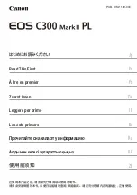
High Definition Video Camera
Model No.
HDC-HS300P
HDC-HS300PC
HDC-HS300EB
HDC-HS300EC
HDC-HS300EE
HDC-HS300EF
HDC-HS300EG
HDC-HS300EP
HDC-HS300GC
HDC-HS300GK
HDC-HS300GT
HDC-HS300SG
Vol. 1
Colour
(K)...........Black Type
(S)...........Silver Type (only GC)
4
Summary of Contents for HDC-HS300P
Page 11: ...11 3 5 2 Precautions for installing HDD...
Page 14: ...14 4 Specifications...
Page 15: ...15...
Page 16: ...16...
Page 29: ...29 7 Disassembly and Assembly Instructions 7 1 Disassembly Flow Chart 7 2 PCB Location...
Page 33: ...33 7 3 4 Removal of the HDD Unit Fig D5 7 3 5 Removal of the Top Case Unit Fig D6...
Page 38: ...38 Fig D20 7 3 15 Removal of the Monitor P C B Fig D21 Fig D22...
Page 39: ...39 7 3 16 Removal of the LCD Fig D23 7 3 17 Removal of the Front P C B Fig D24...
Page 41: ...41 Fig D27 7 3 20 Removal of the Barrier Unit and MF Ring Ornament Fig D28...
Page 42: ...42 7 3 21 Removal of the Flash Unit Fig D29 7 3 22 Removal of the ECM Fig D30 Fig D31...
Page 89: ...S 38...
Page 102: ...S6 3 EVF Section S 51 B45 55 B44 52 56 57 58 59 53 54 43 44 47 46 48 49 50 51 45 60 62 61 B46...