background image

©

2005 Matsushita Electric Industrial CO., Ltd. All

rights

reserved.

Unauthorized

copying

and

distribution is a violation of law.
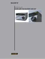
DMR-ES10EB
DMR-ES10EC
DMR-ES10EG
DMR-ES10EP
DMR-ES10EBL

Vol.1

Colour
(S).......... .............S ilver Type
(K).......... .............B lack Type

DVD Video Recorder

ORDER NO.DSD0503039C2

Summary of Contents for Diga DMR-ES10EB

Page 1: ...strial CO Ltd All rights reserved Unauthorized copying and distribution is a violation of law DMR ES10EB DMR ES10EC DMR ES10EG DMR ES10EP DMR ES10EBL Vol 1 Colour S S ilver Type K B lack Type DVD Video Recorder ORDER NO DSD0503039C2 ...

Page 2: ...2 DMR ES10EB DMR ES10EC DMR ES10EG DMR ES10EP DMR ES10EBL ...

Page 3: ...3 DMR ES10EB DMR ES10EC DMR ES10EG DMR ES10EP DMR ES10EBL ...

Page 4: ...C B 28 12 4 Checking and Repairing of DVD RAM Drive 29 13 Caution after replacing parts 30 13 1 After replacing the RAM Drive with new one 30 13 2 When the unit does not operate normally after replacing the Timer Microprocessor or Main P C B 30 14 Standard Inspection Specifications after Making Repairs 30 15 Voltage and Waveform Chart 31 15 1 Power P C B 31 15 2 Main P C B 31 15 3 Tuner P C B 33 1...

Page 5: ...ure the potential across the resistor 4 Check each exposed metallic part and measure the voltage at each point 5 Reverse the AC plug in the AC outlet and repeat each of the above measurements 6 The potential at any point should not exceed 0 75 volts RMS A leakage current tester Simpson Model 229 or equivalent may be used to make the hot checks leakage current must not exceed 1 2 milliampere In cas...

Page 6: ...d tip soldering iron to solder or unsolder ES devices 4 Use only an anti static solder removal device Some solder removal devices not classified as anti static ESD protected can generate electrical charge sufficient to damage ES devices 5 Do not use freon propelled chemicals These can generate electrical charges sufficient to damage ES devices 6 Do not remove a replacement ES device from its prote...

Page 7: ...g point is 50 70 F 30 40 C higher Please use a high temperature soldering iron In case of the soldering iron with temperature control please set it to 700 20 F 370 10 C Pb free solder will tend to splash when heated too high about 1100 F 600 C When soldering or unsoldering please completely remove all of the solder on the pins or solder area and be sure to heat the soldering points with the Pb fre...

Page 8: ...5 Each Button For DMR ES10EC EG EP 8 DMR ES10EB DMR ES10EC DMR ES10EG DMR ES10EP DMR ES10EBL ...

Page 9: ...For DMR ES10EB EBL 9 DMR ES10EB DMR ES10EC DMR ES10EG DMR ES10EP DMR ES10EBL ...

Page 10: ...iple In the power off at Quick start only power supplies for video IC tuner and storage media are cut off When the REC button is pushed a few second after the power button is pushed Audio and Video data are stored in DDR SDRAM before a storage media DVD RAM or HDD preparation Preparation time DVD RAM Fabout 8seconds After a storage media DVD RAM or HDD preparation Audio and Video data are transfer...

Page 11: ...nd press STOP CH UP keys on the front panel simultaneous ly for 5 seconds 7 2 When the Forcible Disc Eject can not be done 1 Turn off the power and pull out AC cord 2 Remove the Top Case 3 Remove the Front Panel 4 Remove 4 screws and Upper Base Unit from DVD RAM Drive 5 Take out the disc and put the Opener Roller on fully position for direction of Arrow 6 Put the Upper Base Unit so that the Opener...

Page 12: ...curring press 0 2 1 9 keys of the Remote Controller so that 19 memories can be displayed as maximum 2 Press 4 2 keys of remote controller Example of FL Display 1 Error Number is displayed for 5 seconds 2 Time when the error has occurred is displayed for 5 seconds 3 Last Drive Error 1 2 is displayed for 5 seconds 4 Last Drive Error 2 2 is displayed for 5 seconds 12 DMR ES10EB DMR ES10EC DMR ES10EG ...

Page 13: ...TA LEAD DATA Taiwan 15 CMC CMC Taiwan 16 AUVISTAR AUVISTAR Taiwan 17 ACER Acer Taiwan 18 VIVASTAR VIVASTAR Switzerland 19 LGE LG Electronics Korea DVD RAM Disc No FL Display Disc Maker s ID Disc Maker Country 1 MEI Panasonic 2 MATSUSHITA Panasonic Japan 3 MXL Maxell Japan 4 PRODISC Prodisc Taiwan 5 OPTDISC OPTDISC Taiwan 6 CMC CMC Taiwan Since an display is arbitrarily set up by the disk producer ...

Page 14: ...Error Occurring Disc State 14 DMR ES10EB DMR ES10EC DMR ES10EG DMR ES10EP DMR ES10EBL ...

Page 15: ...alization is possible with error code initialization and main unit initialization No display No display F58 Drive hardware error When drive unit error is detected the event is saved in memory No display No display F34 Initialization error when main microprocessor is started up for program recording When initialization error is detected after starting up main microprocessor for program recording th...

Page 16: ...ion Lock is being set this Forced disc eject function is not accepted The display before execution leaves When the power is off press STOP and CH UP keys simultaneously for 5 seconds Child lock unlock Set or release Child Lock Press ENTER and RETURN by remote controller simultaneously until X HOLD is displayed NTSC PAL system select To switch PAL NTSC alternately The display before execution leave...

Page 17: ...displayed for 3 seconds When the power is on press STOP and POWER keys simultaneously for 5 seconds When press OPEN CLOSE key while the tray being locked Display LOCK for 3 seconds Press OPEN CLOSE key while the tray being locked ATP re execution Re execute ATP Display at ATP executing When the power is on E E mode press CH UP and CH DOWN simultaneously for 5 seconds Progressive initialization The...

Page 18: ...White Picture Output mode I P are switched alternately Magenta Picture Output Magenta picture is output with Component Output from AV Decoder Magenta picture Saturation rate 100 It is enable to switch Interlace Progressive by I P switch 1 4 Initial mode is Interlace Press 1 2 in service mode Switch Interlace Progressive Press 1 4 in Magenta Picture Output mode I P are switched alternately RTSC Ret...

Page 19: ...ed Time Laser used time stored in the memory of the unit is deleted Press 9 5 in service mode RAM Drive Last Error RAM Drive error code display For details about the drive error code refer to the Service Manual for the specific RAM Drive Details are described in 8 Service Explorer 1 Error Number is displayed for 5 seconds 2 Time when the error has occurred is displayed for 5 seconds Y Year MM Mont...

Page 20: ...time Indicating unit Second Press 6 4 in service mode Display the Error History Display the Error History stored on the unit Display reason of error for 5 seconds Display the time when the error has occurred for 5 seconds YY Year MM Month DD Day HH Hour MM Minute Accumulated working time till occuring of the error is left displayed Indicating unit Second Press 6 5 in service mode Then press 0 1 1 ...

Page 21: ... tray is opened and closed repeatedly is number of open close cycle times Press 9 1 in service mode When releasing this mode press the POWER button of Remote Controller more than 10 seconds Error code initialization Initialization of the last error code held by timer Write in F00 Press 9 8 in service mode Initialize Service Last Drive Error Error history and Error Codes stored on the unit are init...

Page 22: ...ng chart is the procedure for disassemblin g the casing and inside parts for internal inspection when carrying out the servicing To assemble the unit reverse the steps shown in the chart below 10 2 P C B Positions 22 DMR ES10EB DMR ES10EC DMR ES10EG DMR ES10EP DMR ES10EBL ...

Page 23: ... 4 Front Panel 1 Unlock 2 tabs A and 3 tabs B in this order to remove Front Panel The tab A and B should be unlocked at the same time respectively 10 5 Digital P C B 1 Remove FFC and a Screw A 2 Lift up Digital P C B slightly so to disconnect Connector to remove Digital P C B CAUTION 1 When replacing Digital P C B pay attention as below 23 DMR ES10EB DMR ES10EC DMR ES10EG DMR ES10EP DMR ES10EBL ...

Page 24: ... between DVD RAM Drive and Main P C B 10 7 Power P C B 1 Remove Screw A 2 Remove 3 Screws B and disconnect Connector A 3 Unlock Power P C B from a Flange to remove Power P C B 10 8 Rear Panel 1 Remove 7 Screws A and Screw B 2 Unlock 2 Locking Tabs A to remove Rear Panel 24 DMR ES10EB DMR ES10EC DMR ES10EG DMR ES10EP DMR ES10EBL ...

Page 25: ...emove 9 Screws A 3 Remove Power P C B Angle Digital P C B Angle and disconnect Connector A to remove Main P C B 10 11 Tuner P C B and Nicam Decoder P C B 1 Pull out the Tuner P C B in the direction of the arrow 2 Remove the solders and pull out the Nicam Decoder P C B 25 DMR ES10EB DMR ES10EC DMR ES10EG DMR ES10EP DMR ES10EBL ...

Page 26: ... P C B DVD RAM Drive 4 Pin Same as E30 HS2 series RFKZ0216 Extension Cable Main P C B Power P C B 23 Pin Same as E55 series RFKZ0260 Extension Cable Main P C B Digital P C B 88 Pin New 12 Service Positions Note For description of the disassemblin g procedure see the section 10 12 1 Checking and Repairing of Power P C B 26 DMR ES10EB DMR ES10EC DMR ES10EG DMR ES10EP DMR ES10EBL ...

Page 27: ...12 2 Checking and Repairing of Digital P C B 27 DMR ES10EB DMR ES10EC DMR ES10EG DMR ES10EP DMR ES10EBL ...

Page 28: ...12 3 Checking and Repairing of Main P C B 28 DMR ES10EB DMR ES10EC DMR ES10EG DMR ES10EP DMR ES10EBL ...

Page 29: ...12 4 Checking and Repairing of DVD RAM Drive 29 DMR ES10EB DMR ES10EC DMR ES10EG DMR ES10EP DMR ES10EBL ...

Page 30: ...n recording and playback 5 If a problem is caused by a VCD DVD R DVD Video Audio CD or MP3 playback the test disc No abnormality should be seen in the picture sound or operation 6 After checking and making repairs upgrade the firmware to the latest version Make sure that FIRM_SUCCESS appears in the FL displays UNSUPPORT display means the unit is already updated to newest same version Then version ...

Page 31: ...E C B REC 0 4 5 0 PLAY 0 4 5 0 STOP 0 4 5 0 QR1801 IC1150 Q1600 Q1700 QR1301 QR1302 QR1303 QR1304 IC1401 QR1800 IC1200 IC1400 IC1701 Q1200 Q1270 IC1601 15 2 Main P C B Ref No MODE 1 2 3 4 5 6 7 8 1 2 3 4 5 6 7 8 REC 5 0 0 0 3 4 4 9 0 0 5 0 3 3 0 0 2 0 4 9 0 0 3 6 PLAY 5 0 0 0 3 4 4 9 0 0 5 0 3 3 0 0 2 0 4 9 0 0 3 6 STOP 5 0 0 0 3 4 4 9 0 0 5 0 3 3 0 0 2 0 4 9 0 0 3 7 Ref No MODE 1 2 3 4 5 1 2 3 4 ...

Page 32: ...C 0 4 9 4 9 0 0 0 0 0 5 0 0 0 0 0 0 0 0 4 9 0 0 4 1 PLAY 0 4 9 4 9 0 0 0 0 0 5 0 0 0 0 0 0 0 0 4 9 0 0 4 1 STOP 0 4 9 4 9 0 0 0 0 0 5 0 0 0 0 0 0 0 0 4 9 0 0 4 1 Ref No MODE 81 82 83 84 85 86 87 88 89 90 91 92 93 94 95 96 97 98 99 100 REC 0 5 0 0 0 0 0 4 9 0 0 0 0 0 4 9 0 5 0 4 9 0 6 2 3 4 7 3 2 PLAY 0 5 0 0 0 0 0 4 9 0 0 0 0 0 4 9 0 5 0 4 9 0 6 2 3 4 7 3 2 STOP 0 5 0 0 0 0 0 4 9 0 0 0 0 0 4 9 0 4...

Page 33: ...04 Q7504 Q7506 Q3907 Q3908 Q3909 Q3910 Q4004 QR4002 QR4003 Q4006 Q4007 Q7507 Q7508 Q7510 QR4005 Q7401 Q7501 Q7502 Q7503 Q4009 Q4008 QR4004 QR3914 15 3 Tuner P C B Ref No MODE E C B REC 3 8 1 2 3 1 PLAY 3 8 1 2 3 1 STOP 3 8 1 2 3 1 Ref No MODE E C B E C B REC 0 0 6 0 0 0 0 6 PLAY 0 0 6 0 0 0 0 6 STOP 0 0 5 0 0 0 0 4 Q7802 QR7806 QR7807 15 4 P9001 Connector Ref No MODE 1 2 3 4 5 6 7 8 9 10 11 12 13 ...

Page 34: ...p p 20 sec div P7402 63 REC PLAY 0 6Vp p 20 sec div P7402 59 REC PLAY 1 0Vp p 20 sec div P7402 51 REC PLAY 0 8Vp p 20 sec div P7402 47 REC PLAY 1 0Vp p 20 sec div P7402 29 31 REC PLAY 0 7Vp p 1m sec div P7402 55 REC PLAY 0 6Vp p 20 sec div JK3903 3 REC PLAY 1 0Vp p 20 sec div JK3903 2 REC PLAY 1 0Vp p 20 sec div JK3903 4 REC PLAY 2 0Vp p 20 sec div 34 DMR ES10EB DMR ES10EC DMR ES10EG DMR ES10EP DM...

Page 35: ...DIGITAL SERVO CONTROLLER DATA SLICE LOOP FILTER DIGITAL VIDEO DISC INITIAL LOGO ABBREVIATIONS E EC ECR ENCSEL ETMCLK ETSCLK ERROR TORQUE CONTROL ERROR TORQUE CONTROL REFERENCE ENCODER SELECT EXTERNAL M CLOCK 81MHz 40 5MHz EXTERNAL S CLOCK 54MHz F FBAL FCLK FE FFI FEO FG FSC FSCK FOCUS BALANCE FRAME CLOCK FOCUS ERROR FOCUS ERROR AMP INVERTED INPUT FOCUS ERROR AMP OUTPUT FREQUENCY GENERATOR FREQUENC...

Page 36: ...SUB CODE Q DATA SYSTEM CLOCK T TE TIBAL TID TIN TIP TIS TPSN TPSO TPSP TRCRS TRON TRSON TRACKING ERROR BALANCE CONTROL BALANCE OUTPUT 1 BALANCE INPUT BALANCE INPUT BALANCE OUTPUT 2 OP AMP INPUT OP AMP OUTPUT OP AMP INVERTED INPUT TRACK CROSS SIGNAL TRACKING ON TRAVERSE SERVO ON INITIAL LOGO ABBREVIATIONS V VBLANK VCC VCDCONT VDD VFB VREF VSS V BLANKING COLLECTOR POWER SUPPLY VOLTAGE VIDEO CD CONTR...

Page 37: ...3 IC1401 VIN VOUT REG DR 5V D1401 QR1303 POWER ON OFF CONTROL SW QR1302 ON FET D S G Q1270 DR 12V OUT 1 2 3 5 6 7 8 X SW 12 4V 4 QR1304 ON FET D S G Q1700 REG X SW 3 8V 4 3 1 2 5 6 1 2 7 DC DC CONVERTER 6 Vin IC1701 GND PW ON FET Gate Drive 4 3 2 1 Q1200 FEED BACK 1 2 3 IC1200 ERROR VOLTAGE DET COLD HOT P1102 P1501 4 5 D 1 5V P1102 P1102 P1501 P1501 11 12 13 P1102 P1501 2 3 P1102 P1501 15 P1102 P1...

Page 38: ...SECTION 50 IC7501 JC P ON CONT GND 8 5 3 1 VIN VOUT IC1502 REG ANA 3 3V GND 1 5 3 VIN VOUT IC1504 REG D 3 3V CONT 5 GND 8 3 1 VIN VOUT IC1505 REG X SW 3 3V 82 84 86 88 P7402 P9001 8 1 VIN REG D 1 2V VOUT IC9001 3 IC3201 208 234 D 1 2V 48 52 P7402 P9001 IC3206 6 18 26 ANA 5V 17 P7402 P9001 REG DAC 3 3V IC4409 VOUT ON 6 2 3 GND 1 VIN 5 GND 2 1 VDD RESET OUT IC7506 ON QR7506 INV SW IC7501 81 68 70 72...

Page 39: ... 19 20 AV4 Y OUT b a SW7 22 AV4 C OUT SW8 b a 23 24 AV4 V OUT SW9 b a a b c d e SV1 26 AV1 V Y C OUT a b c d e SV2 28 AV2 V OUT ADC OUTPUT SELECT SWITCH CIRCUIT AV1 V AV3 Y AV3 C AV3 V AV4 V AV4 Y AV4 C AV2 R C AV2 V Y TUNER V 81 C ADC OUT 83 V Y ADC OUT 85 SLICER CLAMP BIAS CLAMP CLAMP BIAS CLAMP CLAMP CLAMP SW10 SLICER Q7501 Q7503 B IIC CLK IC7501 28 29 IC7501 IIC DATA FROM TO TIMER SECTION 88 S...

Page 40: ...ICAM A2 3 PK7301 PK7701 1 PK7301 PK7701 5 PP7401 PS7801 4 PP7401 PS7801 NICAM DECODER P C B 14 15 16 PS7801 PP7401 PP7401 PS7801 15 AUDIO OUT SIF OUT 76 RF OUT RFC A MUTE IC7501 75 2 AUDIO IN TU7801 U V TUNER MUTE QR7806 7807 EC EG EB ONLY FROM TIMER SECTION TUNER P C B MUTE VCA MIX AGC ADC Rch AMP LPF BUFF MUTE a b c d MUTE BUFF LPF MUTE BUFF LPF ADC Lch AMP AGC MUTE BUFF LPF 72 AV1 Rch ADC Rch 7...

Page 41: ...19 SEG25 SEG26 17 45 SEG35 SEG39 49 63 DIG00 DIG07 56 1 RESET 93 1 47 44 13 12 7 P1 P32 3G 8G F F DP7501 TIMER DISPLAY 4 FL TXD KEY IN1 KEY IN2 KEY IN3 11 5 4 RESET IC7502 X SW 5 2V 6 10 VDD GND CTL 81 SYS PFAIL 2 1 VDD OUT IC7506 RESET D 3 3V RESET 2 X SW 5 2V OUT IC7505 VDD 1 PFAIL 80 PLAY POWER S7001 P7001 P7506 3 FRONT L P C B 9 1 3 8 HEATER B HEATER 38V GND 7 6 DISPLAY HEATER POWER SWITCHING ...

Page 42: ...DMR ES10EB DMR ES10EC DMR ES10EG DMR ES10EP DMR ES10EBL 42 ...

Page 43: ...SDA DECODER AUDIO R GND DECODER AUDIO L PK7702 PK7301 PK7302 NICAM DECODER P C B POWER 1 2 3 4 5 6 7 8 9 10 11 12 13 14 15 16 17 18 19 20 21 22 23 X SW 5 8V X SW 5 8V X SW 12 4V GND GND GND GND GND POWER ON D1 5V D1 5V X SW 3 8V DR P ON DR12V DR12V DRGND DRGND DR5V DR5V X SW 12 4V DR5V DRGND DR12V DR P ON X SW 3 8V D1 5V D1 5V POWER ON GND GND GND GND GND X SW 12 4V X SW 12 4V X SW 5 8V X SW 5 8V ...

Page 44: ...003 ERROR VOLTAGE DET 1 3 2 C A R G 11 F1101 R1150 18 D1151 B0HAGM000006 IC1150 C0DACZH00017 SWITCHING IC PT D1152 MAZ4100NMF R1154 9100 R1157 510 C1151 1000P D1155 MAZ73000BC R1155 470 R1156 16K C1154 1000P C1153 2200P D1156 MA2C165001VT C1152 330P R1152 10K R1151 6800 250V T2AL 2 1 4 3 L1121 G0B233D00001 D1270 B0JBSG000010 1 2 3 R1209 1K R1208 2200 R1153 18 C1270 16V1500 C1271 16V1500 R1207 10K ...

Page 45: ... R1404 1K C1406 6V680 L1401 33u R1401 100K C1405 1000P C1400 25V220 C1401 1 C1402 0 01 C1403 390P C1404 4700P A C B Vin ON Vout Vadj GND IC 1 2 3 4 5 IC1401 C0CBCYG00004 REG DR 5V D G Q1600 B1DHED000008 REG XSW 5 8V OUT S 1 2 3 4 5 6 7 8 R1402 820 P C1601 25V220 C1602 0 1 C1603 0 1 R1602 51K C1605 180P C1604 0 1 R1601 15M C1606 0 01 C1607 10V680 R1603 2400 R1605 2700 R1604 15K L1601 15u LB1600 J0J...

Page 46: ... DRIVE DR P ON DIP ON T T 1 2 3 4 5 6 7 8 REFERENCE TERMINAL SHUTDOWN BIAS DRIVER CURRENT LIMITTER GND REG ANA 5V IC1501 C0CBCDD00006 CONT Vin Vout AV X SW 5 8V A IC GND Vadj 1 Vout ON Vin 2 3 4 5 REG PS 11 6V IC7401 C0CBCYG00004 1 2 IP1501 K5H3022A0013 P 1 2 3 4 5 6 7 8 REFERENCE TERMINAL SHUTDOWN BIAS DRIVER CURRENT LIMITTER GND REG X SW 3 3V IC1505 C0CBCBD00018 CONT Vin Vout R1503 3300 R1504 10...

Page 47: ...T JC P ON JC REG 5V T C7405 0 1 BOOSTER 5V AV BOOSTER5V GND GND JCREG5V SW2 IIC CLK IIC DATA AFC SIF OUT UNREG38V TUNER VIDEO IN 18 17 16 15 14 13 12 11 10 9 8 7 6 5 4 1 3 2 TO PS7801 Tuner P C B PP7401 GND DGND C1517 470P R1507 1800 R1508 820 R1506 10K SIF GND JC REG 5V 7 6 5 4 3 2 1 SCL SDA 6 5 4 3 2 1 DECODER AUDIO R TO PK7302 PK7702 TO PK7301 PK7701 GND DECODER AUDIO L TO Nicam Decoder P C B R...

Page 48: ...0JBC0000011 LB3007 J0JBC0000011 LB3005 J0JBC0000011 P50 K3901 0 B A C4056 16V470 C4055 0 1 DIP ON T G AADC L A M G AADC R A M G CIN DM A M G V YIN DM A M G SLICER A T G IIC CLK A T G IIC DATA A T V SYNC DET T G COUT DM A M G YOUT DM A M G BPBOUT DM A M G RPROUT DM A M G GPYOUT DM A M T T AV4 S IN C4033 16V47 R4046 7500 R4055 12K K4004 C4092 16V100 K4006 R4066 10K K4008 C4061 0 1 C4057 33P R4057 12...

Page 49: ...UT AV2 V OUT VGND TUNER V IN AV2 V Y IN AV2 FB IN AV1 V IN AV1 FB OUT AV4 V IN EXT CTL3 AV3 V IN EXT CTL4 AV4 Y IN VCC 5V AV3 Y IN VCC ALL 5V AV4 C IN 1 2REF GND AV3 C IN VCC 11 6V DT Y IN DT C IN 1 2REF FRONT RIN AV4 RIN AV1 RIN AV2 RIN TU RIN DT RIN DA RIN 9VR FRONT LIN AV4 LIN AV1 LIN AV2 LIN TU LIN DT LIN DA LIN 9VL 9VREG GND METER L METER L METER R METER R AV1 LOUT AV1 ROUT AV2 LOUT AV2 ROUT ...

Page 50: ...7555 0 01 C7554 0 01 R7582 100K TL7512 C B M M M M M M M M M M M R7622 15K R7620 47K DMR ES10EB EC EG EBL EP Timer Section Main P C B 3 3 Schematic Diagram R7569 0 C7539 47P C7540 0 01 C7541 47P C7542 0 1 C7543 47P C7544 0 1 R7559 2K R7558 2K R7557 510 R7607 100 R7599 8200 R7598 8200 R7597 8200 C7516 18P C7517 18P C7518 22P C7519 18P C7524 0 1 R7527 100 R7529 100 R7528 100 R7532 3300 C7523 0 01 C7...

Page 51: ...7 R7617 330 C7573 50V22 D7508 MAZ4240NMF D7507 B0AAGM000007 LB7517 0 C7572 10V220 R7518 27K C7511 100P SW2 WIDE AV2 PB AV3 S IN M M AV AV P50 AV EPG MUTE AV XTMUTE 3 2 1 POWER SW ON GND GND P7506 M DDGND M GND M M JC P ON DR P ON M PWR SAVE M DIP ON AV R7571 100 D7504 MAZ4300NLF C B A UNREG 38V M C7569 2200P R7614 47 C7565 25V220 R7612 3300 L7501 39u C7512 0 1 R7639 2700 R7640 2700 R7644 2200 R764...

Page 52: ... C7809 0 01 C7813 6V47 C7822 0 01 R7815 470 C7818 33P C7825 100P LB7803 J0JHC0000032 C7819 33P R7816 470 C7820 0 1 C7824 6V47 D7802 MAZ4300NMF C7821 0 01 C7814 50V22 R7817 470 R7811 470 LB7804 J0JHC0000032 R7818 220 TL7401 NOTE DO NOT USE THE PART NUMBER SHOWN ON THIS DRAWING FOR ORDERING THE CORRECT PART NUMBER IS SHOWN IN THE PARTS LIST AND MAY BE SLIGHTLY DIFFERNT OR AMENDED SINCE THIS DRAWING ...

Page 53: ...4 1000P C7323 J0JCC0000124 LB7301 B A B B A B A A B 0 R7322 H0D245500016 B H0H400400006 A X7301 0 1 C7332 C7316 4700P A A B C7319 1500P B B C7333 0 1 B 0 47 A C7326 470K C7325 0 01 C7336 0 1 C7331 0 012 C7330 680P R7323 5600 C7337 470K R7325 100 R7324 100 100P C7311 B 10P C7307 10P C7308 C7310 100P B 1500P A 100P B 1500P A C7309 A B C7302 0 0 R7301 0 1 B 0 01 A C7301 3 2 1 50V2 2 C7334 0 01 C7306 ...

Page 54: ...DMR ES10EB DMR ES10EC DMR ES10EG DMR ES10EP DMR ES10EBL 54 ...

Page 55: ...R1703 C 2 Q1270 D 2 D1400 B 2 LB1700 C 2 C1274 D 3 C1704 C 3 R1209 D 5 R1704 C 3 Q1600 B 4 D1401 D 3 C1400 B 3 C1705 C 3 R1210 D 5 R1705 C 3 Q1700 C 2 D1601 B 4 F1101 D 9 C1401 B 3 C1706 C 3 R1270 D 3 R1800 B 5 D1701 C 2 C1402 B 3 C1707 C 2 R1271 D 3 R1801 B 5 QR1301 B 3 D1800 B 5 C1120 D 8 C1403 B 3 C1800 B 5 R1311 D 5 R1802 B 5 QR1302 E 4 C1121 B 8 C1404 B 3 R1401 B 2 R1803 B 5 QR1303 E 4 IP1601...

Page 56: ...EP EBL EG EC EG EC 1 A B C 2 3 4 DMR ES10EB EC EG EP EBL Main P C B VEP79107B ES10EB VEP79107D ES10EC VEP79107A ES10EG VEP79107M ES10EP EBL 1 4 Section 1 4 2 4 3 4 4 4 Location Map REAR FRONT DMR ES10EB DMR ES10EC DMR ES10EG DMR ES10EP DMR ES10EBL 56 ...

Page 57: ...n EC 5 6 7 8 DMR ES10EB EC EG EP EBL Main P C B VEP79107B ES10EB VEP79107D ES10EC VEP79107A ES10EG VEP79107M ES10EP EBL 1 4 Section 1 4 2 4 3 4 4 4 Location Map REAR FRONT DMR ES10EB DMR ES10EC DMR ES10EG DMR ES10EP DMR ES10EBL 57 ...

Page 58: ...EB D E F DMR ES10EB EC EG EP EBL Main P C B VEP79107B ES10EB VEP79107D ES10EC VEP79107A ES10EG VEP79107M ES10EP EBL 1 4 Section 1 4 2 4 3 4 4 4 Main P C B Location Map REAR FRONT DMR ES10EB DMR ES10EC DMR ES10EG DMR ES10EP DMR ES10EBL 58 ...

Page 59: ...EB EG EB EB EB EG EC EP EBL DMR ES10EB EC EG EP EBL Main P C B VEP79107B ES10EB VEP79107D ES10EC VEP79107A ES10EG VEP79107M ES10EP EBL 1 4 Section 1 4 2 4 3 4 4 4 Location Map REAR FRONT DMR ES10EB DMR ES10EC DMR ES10EG DMR ES10EP DMR ES10EBL 59 ...

Page 60: ... R7597 F 2 Q7503 E 2 X7502 D 3 C1536 F 4 C4003 D 7 C7528 D 3 R3924 E 8 R7410 B 3 R7598 F 2 Q7504 E 3 C1538 B 2 C4005 E 6 C7529 D 3 R3925 D 8 R7421 E 5 R7599 F 2 Q7506 E 4 IP1501 B 6 C1539 A 2 C4006 E 5 C7531 D 3 R3926 D 8 R7422 E 5 R7600 E 3 Q7507 E 4 IP7501 E 2 C1540 A 2 C4008 E 6 C7532 D 3 R3927 D 8 R7438 C 3 R7601 E 3 Q7508 E 4 C3001 D 6 C4011 E 6 C7533 D 3 R3928 E 8 R7439 C 3 R7606 E 3 Q7510 E...

Page 61: ...EC EG VEP07A77B ES10EB VEP07A77C ES10EP EBL EP EBL EP EBL EP EBL EB EB EB EB EB EB EC EG EP EBL EC EG EP EBL EC EG 1 A B C 2 3 4 5 Front L P C B DMR ES10EB EC EG EP EBL Front L P C B VEP70115A 19 3 Tuner P C B Front L P C B DMR ES10EB DMR ES10EC DMR ES10EG DMR ES10EP DMR ES10EBL 61 ...

Page 62: ... ES10EB EC EP EBL Nicam Decoder P C B VEP07A51A For ES10EB EC EP EBL 1 A B C D 2 3 4 5 Nicam Decoder P C B DMR ES10EG Nicam Decoder P C B VEP07A51E For ES10EG 19 4 Nicam Decoder P C B DMR ES10EB DMR ES10EC DMR ES10EG DMR ES10EP DMR ES10EBL 62 ...

Page 63: ...20 Exploded Views 20 1 Casing Parts Mechanism Section 63 DMR ES10EB DMR ES10EC DMR ES10EG DMR ES10EP DMR ES10EBL ...

Page 64: ...20 2 Packing Accessories Section 64 DMR ES10EB DMR ES10EC DMR ES10EG DMR ES10EP DMR ES10EBL ...

Page 65: ... 12 RYP1267E S FRONT PANEL ASS Y1 1 EB EBL 12 RYP1267D S FRONT PANEL ASS Y1 1 EG S EP EC S 12 1 RKF0728 K TRAY DOOR 1 12 2 VMB3410 TRAY SPRING 1 12 3 RMR1698 S SHAFT HOLDER 1 Ref No Part No Part Name Description Pcs Remarks 12 4 RGK1885 S REC BUTTON RING 1 12 5 RGK1886 Q FL ORNAMENT 1 12 6 RKF0729B K PANEL DOOR 1 K 12 6 RKF0729B S PANEL DOOR 1 S 12 7 RHD26045 SCREW 1 12 8 RMX0302 DOOR DAMPER 1 13 ...

Page 66: ...1 EB Ref No Part No Part Name Description Pcs Remarks C4018 F2A1H4R7A236 50V 4 7U 1 EB C4019 F2A1V100A534 35V 10U 1 C4021 F2A1V100A534 35V 10U 1 C4023 F2A1H100A236 50V 10U 1 C4024 F2A1E1010067 25V 100U 1 C4025 F2A1H100A236 50V 10U 1 C4027 F2A1H2200032 50V 22U 1 C4028 F2A1H100A236 50V 10U 1 C4033 3 4 F2A1C470A637 16V 47U 2 C4055 F1H1C104A008 16V 0 1U 1 C4056 F2A1C471A628 16V 470U 1 C4057 ECJ2VC1H33...

Page 67: ...3 K1U407B00004 JACK VIDEO OPTICAL OUT 1 K3901 D0YBR0000002 CHIP RESISTOR 1 EBL EP K4002 D0YDR0000006 CHIP RESISTOR 1 Ref No Part No Part Name Description Pcs Remarks K4012 D0YBR0000002 CHIP RESISTOR 1 EB K7401 D0YBR0000002 CHIP RESISTOR 1 EB K7405 0 6 D0YBR0000002 CHIP RESISTOR 2 EB EBL EP K7503 0 4 D0YBR0000002 CHIP RESISTOR 2 K7506 0 7 D0YBR0000002 CHIP RESISTOR 2 K7512 D0YBR0000002 CHIP RESISTO...

Page 68: ...ption Pcs Remarks R4077 D0GB101JA002 1 10W 100 1 R4078 7 9 D0GB272JA002 1 10W 2 7K 2 R4080 D0GB101JA002 1 10W 100 1 R4081 D0GB821JA002 1 10W 820 1 R4088 8 9 D0GB272JA002 1 10W 2 7K 2 R4090 D0GB221JA002 1 10W 220 1 R4093 D0GB221JA002 1 10W 220 1 R4094 D0GB223JA002 1 10W 22K 1 EG EBL EP EC R4901 D0GB101JA002 1 10W 100 1 R4902 D0GB472JA002 1 10W 4 7K 1 R7401 D0GB122JA002 1 10W 1 2K 1 EG R7401 D0YBR00...

Page 69: ...1 C7838 F2A1E4700048 25V 47U 1 EG EC Ref No Part No Part Name Description Pcs Remarks D7802 MAZ4300NMF DIODE 1 K7807 D0YBR0000002 CHIP RESISTOR 1 EB K7808 D0YBR0000002 CHIP RESISTOR 1 EG EBL EP EC K7809 D0YBR0000002 CHIP RESISTOR 1 EB EG EC K7810 D0YBR0000002 CHIP RESISTOR 1 EG EBL EP EC K7811 D0YBR0000002 CHIP RESISTOR 1 EB L7802 G0C270JA0019 COIL 27UH 1 EB LB7801 J0JHC0000032 COIL 1 EB LB7802 04...

Page 70: ...t No Part Name Description Pcs Remarks R7301 D0YBR0000002 CHIP RESISTOR 1 R7304 D0GB101JA002 1 10W 100 1 EB EBL EP EC R7305 D1BB10000002 RESISTOR 1 EG R7306 D1BB39010002 RESISTOR 1 EG R7307 D0GB472JA002 1 10W 4 7K 1 EG R7307 D0YBR0000002 CHIP RESISTOR 1 EB EBL EP EC R7308 D0GB752JA002 1 10W 7 5K 1 EG R7309 D0GB103JA002 1 10W 10K 1 EB EBL EP EC R7310 1 1 D0GB221JA002 1 10W 220 2 EB EBL EP EC R7312 ...

Page 71: ...RANSISTOR 1 QR1801 UNR221300L TRANSISTOR 1 R1150 ERJ6GEYJ180V 1 8W 18 1 R1151 ERJ6GEYJ682V 1 8W 6 8K 1 R1152 ERJ6GEYJ103V 1 8W 10K 1 R1153 ERJ6GEYJ180V 1 8W 18 1 R1154 ERJ6GEYG912V 1 8W 9 1K 1 R1155 ERJ6GEYG471V 1 8W 470 1 R1156 ERJ6GEYG163V 1 8W 16K 1 R1157 ERJ6GEYG511V 1 8W 510 1 R1158 ERX2SJR22E RESISTOR 1 R1200 ERJ6GEYG122V 1 8W 1 2K 1 R1201 ERJ6GEYG822V 1 8W 8 2K 1 R1205 ERJ6GEYJ224V 1 8W 220...

Reviews: