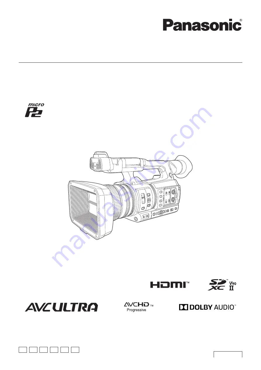
Operating Instructions
Memory Card Camera-Recorder
Before using this product, be sure to read “Read this first!” (pages 2 to 6).
Before operating this product, please read the instructions carefully and save this manual for future use.
ENGLISH
DVQP1830XA
W0219HO2109 -YI
Model No.
AG-CX350
Model No.
AJ-UPX360ED
P
PJ
EN ED AN PX
Summary of Contents for AVC ULTRA AJ-UPX36OED
Page 10: ...Before using the camera read this chapter Chapter 1 Overview ...
Page 191: ...Maintenance of the camera or frequently asked questions are described Chapter 10 Notes ...
Page 201: ...This chapter describes the specifications of this product Chapter 11 Specification ...
Page 210: ...Web Site http www panasonic com Panasonic Corporation 2019 ...