background image


Pall Life Sciences.


USA:


Port Washington, NY, USA 1 800 717 7255 toll free (USA),+1 516 484 5400 phone

,


[email protected] e-mail

, www.pall.com

.  

Europe: Fribourg, Switz41 (0)26 350 53 00 phone, 

[email protected] e-mail.  Asia-Pacific : +65 6389 6500 phone, [email protected] e-mail 
© 2012, Pall Corporation. Pall, Allegro, Kleenpak, Stax and the Allegro Design are trademarks of Pall Corporation. ® 
indicates a trademark registered in the USA and TM indicates a common law trademark. 

Filtration.Separation.Solution 

is a service mark of Pall Corporation.
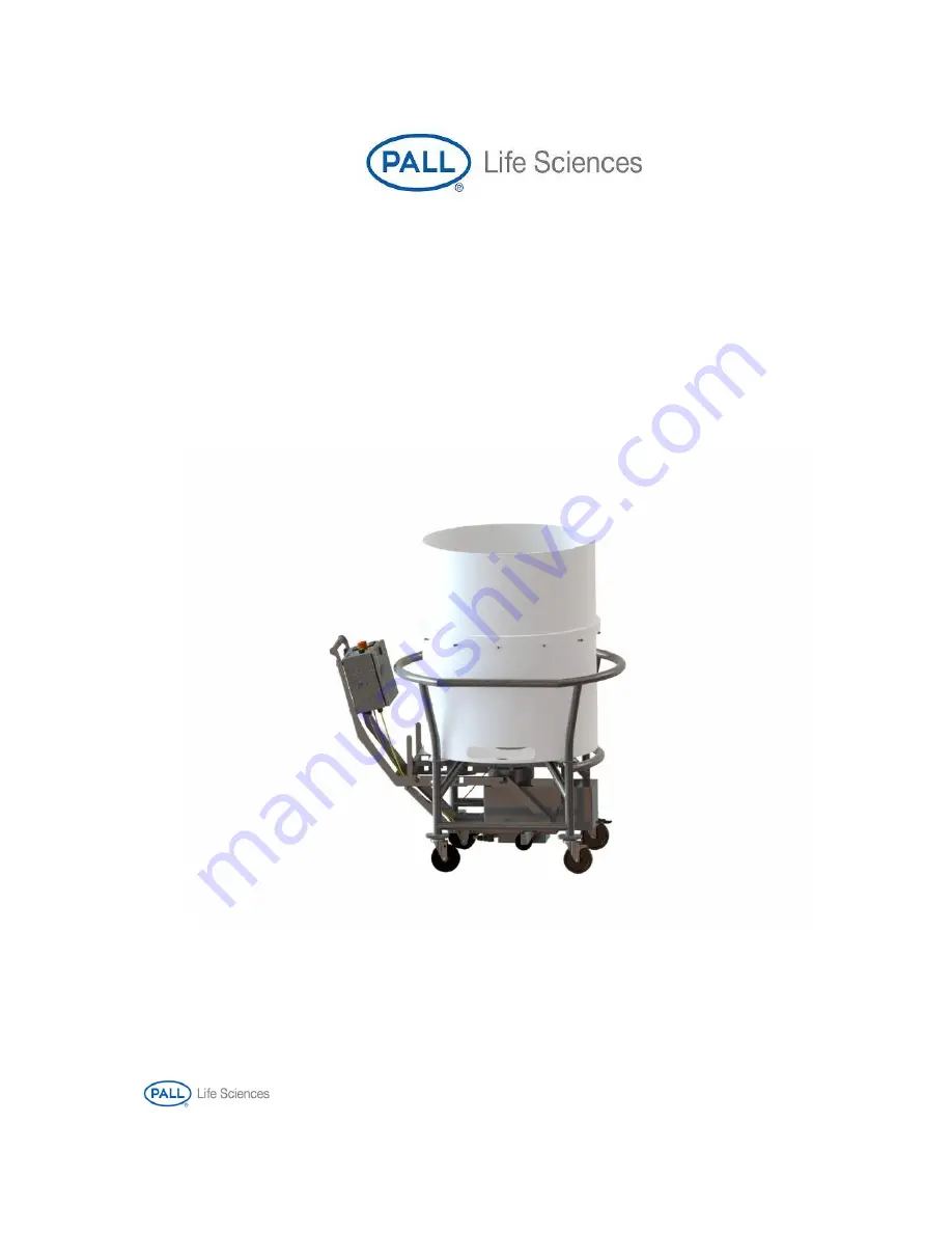


LevMixer

®


Single-Use Mixing System 


OPERATOR MANUAL 


Models DB-300, DB-300C 


USD 3184 

Summary of Contents for LevMixer DB-300

Page 1: ...e mail Asia Pacific 65 6389 6500 phone sgcustomerservice pall com e mail 2012 Pall Corporation Pall Allegro Kleenpak Stax and the Allegro Design are trademarks of Pall Corporation indicates a trademark registered in the USA and TM indicates a common law trademark Filtration Separation Solution is a service mark of Pall Corporation LevMixer Single Use Mixing System OPERATOR MANUAL Models DB 300 DB ...

Page 2: ...ronment it is necessary to wait 1 2 hours to equalize the internal temperatures of the drive unit before powering on 5 Be sure all power is disconnected before opening assembling or disassembling the superconductive drive unit or its control box 6 For full compliance with CE specifications be sure the appropriate ground connection is made 7 For technical assistance contact the sales organization f...

Page 3: ...on bags magnetic chargers and impellers when not in use DO NOT open the machine or control box while the Drive Unit is plugged in DO NOT submerge the drive in water The unit outer surfaces may be cleaned and sanitized by wiping with a mild detergent solution DO NOT cut the ground plug ...

Page 4: ...TROL 14 H CHARGING THE SUPERCONDUCTORS 17 I DOLLY TANK ASSEMBLY 21 J BAG INTERFACE ASSEMBLY 24 K INSERTING MIXING BAG INTO CONTAINER 25 L COUPLING THE BAG WITH SUPERCONDUCTING DRIVE UNIT 26 M MIXING 30 N REMOVING SUPERCONDUCTING DRIVE UNIT FROM TANK 30 O MAINTENANCE CARE OF SUPERCONDUCTING DRIVE UNIT 31 P OPERATOR CONTROL INTERFACE GUIDE 44 Q SPARE PARTS STANDARD ACCESSORIES LISTS 63 R ELECTRICAL ...

Page 5: ...on Mode of control remote local indication Signal type s for remote output control Impeller speed out 4 20mA motor control in 0 10 VDC discrete I O signals relay contact type Alarms generated Motor failure impeller coupling failure speed off range failure cryocooler failure E stop activation Mixer charge time 35 minutes Operator interface type Touchscreen PLC Method for RPM measurement Direct meas...

Page 6: ... PRINCIPLE OF OPERATION The LevMixer s mixing technology is based on non contact magnetic coupling between conventional permanent magnets in the impeller and superconducting material in the drive Superconducting material has the ability to trap the magnetic field generated by the permanent magnets and lock the magnetic field in memory in an equilibrium position Figure 1 Noncontact magnetic couplin...

Page 7: ...ry stable mechanical coupling with finite equilibrium separation This peculiar stability cannot be attained in conventional mixer designs that employ two permanent magnets The Cryogenic temperatures approx 200o C required for the superconducting material are achieved by an internal cryocooler Sterling cycle refrigerator ...

Page 8: ...Document 020 17475 00 Revision E Page 8 of 63 F MIXING SYSTEM COMPONENTS AND ACCESSORIES Figure 2 Main components of LevMixer system ...

Page 9: ...DBAK011 and Magnetic Charger DBCI005 coupled with Shield During the charging procedure the ball bearing red in far left picture should rest on the surface of the levitation head of the drive unit Magnetic Charger Test Impeller Chart Note the appropriate magnetic charger must be used to set the drive machine for use with the corresponding impeller The machine will not properly drive an impeller whi...

Page 10: ...Document 020 17475 00 Revision E Page 10 of 63 Figure 5 Top Drive bag interface Bottom Interface is installed in the railed port of the dolly held in place by the O ring ...

Page 11: ...Document 020 17475 00 Revision E Page 11 of 63 Figure 6 Magnetic clamp left and centering aligner right Figure 7 Magnetic clamp is assembled with centering aligner prior to attachment to the bag ...

Page 12: ...nd alarm status The LevMixer can be operated in one of three modes selected by the operator from the Main Menu Manual mode Automatic mode and Remote mode Each mode includes a specific set of functions to support processing requirements Two auxiliary modes of operation can be activated by the system Power Up mode used to monitor the unit is properly charged and Failure mode used to notify the opera...

Page 13: ...ANT If the drive unit charging phase has not been completed it is possible the Levmixer will not levitate correctly In order to ensure proper levitation in those cases turn the unit off wait for at least 25 minutes and then charge it following the standard procedure as described in section H For details of operation see Section P Operator Control Interface Guide Figure 8 Face panel of control box ...

Page 14: ...nce be set for the impeller type installed within the single use mixing bag the drive unit will operate Pall single use mixing bags employ the 4 magnet set up as a standard although the 6 magnet format is available for select applications 5 If the LevMixer is transported or stored in temperatures colder than the operating environment it is necessary to wait 2 hours to equalize the internal tempera...

Page 15: ...a charging timer will indicate the elapsed charging time in the charging status area bottom row of power up screen 8 Superconductor charging will take approximately 35 minutes After charging is complete a blinking READY button will appear on the screen and the CHARGED notice will be displayed instead of charging time Charging is complete assuming the charger was placed on the levitation head prior...

Page 16: ... The levitated impeller will spin The levitation gap should remain uniform with no significant wobbling of the impeller 15 In the Manual Mode window press and hold STOP button until top bar of the window is filled 2 3 sec 16 When impeller stops rotating remove it from above the levitation head Do not try to remove the test impeller while it is spinning Replace the protective shield on the test imp...

Page 17: ...rs and dollies tanks up to and including 350L use a centrally located impeller and therefore use the central port dolly configuration PALL standard 500L bags use off center impeller and therefore use the off center port dolly configuration See procedure below for changing the dolly port configuration CHANGING DOLLY CONFIGURATION BETWEEN CENTER AND OFF CENTER IMPELLER PORT 1 Determine which port co...

Page 18: ... adjusters with the screws provided 3 To set the rails for the off center 8 port position set the right and left adjusters so that the side with words OFF CENTER is visible on both See figures 15 and 16 Ensure that the two dot marks on the right adjuster are located next to the two dot marks on the rail and single dot mark of the left adjuster is located next to the single dot mark on the left rai...

Page 19: ...e 1 Carefully open the EXTERNAL packaging of the mixing bag A protective shield is magnetically attached to the outside of the bag over the Impeller seat This shield must be removed from the bag before assembling the interface 2 Assemble the centering aligner and magnetic clamp on the outside of the bag as shown in Figure 17 ...

Page 20: ...drain port opening 2 Insert the magnetic clamp into the port 3 Before filling the bag ensure that the bottom drain tube is clamped If the bag contains an EZ Drain ensure the drain is fully closed and clamp the drain in place using the provided plastic drain clip 4 As bag starts to fill gently pull the bottom surface of the bag to remove any wrinkles especially near the impeller DO NOT exceed recom...

Page 21: ...rations can be switched following the procedure described in Section O Each configuration allows connection of the unit to different rail ports using a universal latch Figure 19 Marks on the frame at each latch slot proper positioning of the latch Adjust the universal latch by following the steps shown in figures 20 through 23 Figure 19 The LevMixer shown in standard two left images and expanded t...

Page 22: ... magnetic clamp reach underneath the drive port and carefully pull the magnetic clamp downwards until it is free from the bag tank assembly Return the magnetic clamp to the supplied Accessories Box for future use Figure 21 Universal Latch Removal Step 2 Rotate the latch clockwise until the axle flats are aligned with the horizontal slots Figure 22 Universal Latch Removal Step 3 Slide the latch tow...

Page 23: ...all the way until the bearings rest in the well located at the end of the rails 6 Using the drive unit handle raise the superconductive drive unit to an upright position While holding the drive unit in this position shift the latch toward the dolly tank so that the cross bar rests on the grooves in the guide rails as shown in the fourth step of Figure 24 Figure 24 Coupling of superconducting drive...

Page 24: ... unit slightly to release the locking lever Release the latch by pulling it toward the control box 3 Carefully lower the rear wheels of the drive unit to the floor Roll the drive unit on its rear wheels away from the dolly 4 Press down on the drive unit handle until the guide bearings are free from the guide rails 5 Pull the drive unit away from the dolly until the guide bears are free from the ra...

Page 25: ... of software results in recipes content which is set to factory installed values run time and pause time are zero speed 20 RPM If user defined library content needs to be transferred back in the unit after service is done it is recommended to save the recipe library on a micro SD card prior to conducting software service O 1 PREVENTIVE MAINTENANCE Periodical maintenance is recommended to keep the ...

Page 26: ...arger for mechanical damage Charger magnet damaged Recharge the unit with another charger and perform the levitation test Cryomodule malfunction Call for technical service Impeller doesn t levitate properly after charging completed Unit improperly charged Power off the unit Wait for 25 min or more and charge the unit again Power cord is unplugged from the unit Ensure the power cord is properly att...

Page 27: ...Reset the motor controller alarm Pause about 3 min before starting up motor Avoid frequent starting stopping of the motor Cannot read write to micro SD card Micro card improperly formatted Format micro SD card Power up screen indicates Skipped instead of Charged on charging status Charging skipped during maintenance procedures Turn unit off Wait for at least 25 minutes then start unit and charge i...

Page 28: ...corresponding to the new frame configuration Insert the four carriage screws into four frame connection points The two side bolts should go through bushings as shown in Figure 27 Secure the frame with the four nuts at the connection points Tighten the nuts Make sure the square portion of screw heads are fitted into the square holes in frame Adjust and clip the cables to the frame to fit the frame ...

Page 29: ...n the frame and release the sensor ring cable Unscrew and unplug the sensor ring connector from the rear panel of the Control Box Slip the sensor ring up and off of the levitator head Put the replacement sensor ring over the levitator head Connect the sensor ring connector to the rear panel of control box Place the sensor cable in the cable clips on the frame and lock them Figure 28 Sensor ring re...

Page 30: ...are aligned and the connector plug is pushed all the way in Secure the connector holding cap by rotating it clockwise Tighten the cap firmly to seal the connection Use only power cords provided by PALL for replacement Figure 29 Power cord replacement O 3 4 SD micro card replacement Micro SD cards with up to 2 0 GB of Flash memory are compatible with the Memory slot The PLC uses a FAT 16 file syste...

Page 31: ...nlock control box by rotating the latch counterclockwise using a flat head screwdriver Open the Control Box door and locate the Fuse holder Grip the fuse holder pull upwards and rotate it 90 Unsnap and open the access door on the side of the fuse holder The fuse will now be exposed Remove and replace the fuse by pulling the old one out and snapping the new one into the slot on the access door surf...

Page 32: ...eck to ensure the contact block is firmly seated on the power button and place Cap back on the lever all the way down Close the Control Box door and lock it by rotating the latch clockwise using a flat head screwdriver Figure 32 Contact Block release Figure 33 LED bulb replacement O 3 7 Air Filter inspection To inspect air filter follow steps below Switch the unit off and unplug it from the extern...

Page 33: ... rotation started Wait until the impeller accelerates to its nominal speed of rotation c Reading from external tachometer write into the second column of Table 4 d Calculate and write down in the third column the difference between set point and measured in c speed value e Compare the reading recorded in column 2 with corresponding allowable range in the third column of the Table 4 then record the...

Page 34: ...ng allowable range RPM External Tachometer Max Deviation falls within allowable range Y N Panel Tachometer Max Deviation falls within allowable range Y N 20 19 21 19 21 40 39 41 39 41 60 59 61 59 61 80 79 81 79 81 100 99 101 98 102 120 119 121 118 122 140 139 141 137 143 160 159 161 157 163 180 179 181 176 184 200 199 201 196 204 210 209 211 206 214 Calibration verification is successful if all th...

Page 35: ...mational screens and entry screens All passwords are group passwords with a minimum of six uppercase lower case or numeric characters In total three group logins are available Operator Supervisor and Maintenance Maintenance login is only available while the system is in power up mode The login time period is controlled via a program setup parameter Access is automatically set to the default common...

Page 36: ...el Figure 36 User Login screen Figure 37 Supervisor User Password screen Figure 38 Password entry screen Figure 39 Supervisor Login screen P 3 Power up When the drive unit is turned on the cryocooler will start operating immediately The system will display the Pall LevMixer screen see Figure 40 with the software revision number shown The unit will then automatically enter Power up mode An interact...

Page 37: ...at the superconductors are properly charged One of three modes is possible when the unit is started 1 Superconductors are not charged Charging is required This happens when the unit is powered off for 25 minutes or more Operator must follow the Charging Procedure as described in Section H Charging will start automatically after power is turned ON The PLACE CHARGER IMMEDIATELY notice will display o...

Page 38: ... ready for mixing Figure 44 Power up charging status Figure 45 Power up ready status 2 Superconductors are partially charged Power down is required The on screen notification shows COUPLING INSUFFICIENT The Operator must a Turn the unit off b Wait for at least 25 min c Follow the Charging Procedure as described in Section H This mode can occur if the unit was powered off for 10 min to 25 min after...

Page 39: ...re 46 Main Menu screen Select Auto Mode for the automatic operation mode Select Manual Mode for the manual operation mode Select Remote Mode to control the mixer remotely The three mode screens the Automatic Mode screen the Manual Mode screen and the Remote Mode screen are the locations for setting mixing parameters P 4 Automatic Mode Automatic mode is used to run mixing according to recipes lists...

Page 40: ...elect The Recipe Selector screen will open Figure 48 Use the buttons on the Recipe Selector screen to load recipes and view their contents At the top of the screen press the arrow buttons to move through the list of recipes In the lower right corner of the screen press the Back and Next buttons to move through the individual instructions in the selected recipe On the Recipe Selector screen press t...

Page 41: ...upervisors and maintenance user levels can edit a recipe s instructions To edit a recipe follow these steps 1 Press Select on the Automatic Mode screen The Recipe Selector screen opens Use the arrow buttons at the top of the screen to scroll through the list of recipes until you open the one you want to edit Press Edit The Recipe Editor screen opens Figure 49 If needed press the Back and Next butt...

Page 42: ...recipe name in it An entry screen opens 6 Use the onscreen keyboard and arrows to change the name of the recipe then press enter 7 Press Save to save your changes To return to the Automatic Mode screen without saving your changes to the recipe press Cancel P 5 Manual Mode Use the manual mode to run the mixer either continuously or for a specific amount of time at a given RPM The manual mode is ide...

Page 43: ...un press the Run Period box When the keypad opens enter the amount of time and then press Enter Return to the Manual Mode screen All parameters are indicated in screen areas with white backgrounds Figures 50 and 51 Figure 52 Manual Setup Permanent screen Figure 53 Manual Setup Timed screen Starting a Manual Job To a manual job press and hold the Start button on the Manual Mode screen The mixer wil...

Page 44: ...xer from external equipment to which the mixer is connected Supervisor and Maintenance user levels can switch the mixer between remote and local control Signal circuits for remote control pass through the control box via two connectors located on the back of the control box With a remote control panel the operator is able to Start Stop the motor Change the speed of rotation Read the speed of rotat...

Page 45: ...otation to stop displays an alarm notification to the operator Figure 55 and generates and alarm output signal for remote control The equipment in the drive unit will stay powered up but cannot be operated until failure reset is complete Failure resolution is available only from the LevMixer face panel External control equipment will only receive an alarm signal with no ability to feedback control...

Page 46: ...ified Coupling time the impeller may have decoupled from the mixer s drive When this occurs rotation is stopped and the ALARM appears on the screen The operator should do the following steps a Press the ALARM button The failure detection screen will then open b On the failure detection screen identify the Coupling Off Range failure in the blinking bullet Note the date and time of the failure event...

Page 47: ...turn off power to reset the failure signal d Turn the unit off then turn it back on P 8 Auxiliary functions System functionality is controlled with parameters accessible through the setup editor which is available through the Main menu screen A Setup button will appear on the screen after a user has logged in at the Supervisor or Maintenance level Figure 57 The selection of parameters available fo...

Page 48: ...en Enter the time for auto logout then press Enter 5 View runtime counter indicators for System runtime and Motor runtime Login to the system as Supervisor Press the setup button on the Main menu screen Select the Runtime Hrs function using the up and down arrows Press the curved arrow to go to the view screen The screen will indicate accumulated runtime separately for both system and motor rotati...

Page 49: ...ved arrow to open the next screen Figure 58 Press the File number button to go to the entry screen On the entry screen input the file number 0 9 you wish to Import and press Enter Press the Import recipes button and confirm when prompted Figures 59 and 60 The whole library will be imported from the file on the Micro SD card named LIBRARYX BAK where X is the file number entered on the previous step...

Page 50: ...process Successful Actual duration of recipe run time includes pauses Pause resumed Failure Alarm Unscheduled Aborted P 10 Initial Settings Default settings are the factory preinstalled parameters as listed in the Table6 The parameters can be adjusted through the corresponding editor screens Table6 Initial settings of user interface parameters Description of parameter Units Factory setting Manual ...

Page 51: ... assembly LT SVSP300 2 Sensor Ring assembly LT SVSP301 3 LevMixer Latch LT SVSP315 4 Roller LT SVSP320 5 Mount vibration damping LT SVSP324 6 Replacement Filter Tissue LT SVSP327 7 Timing Belt LT SVSP330 8 Cryocooler Controller 48 VDC Input LT SVSP338 9 Terminating plug LT SVSP341 10 White illuminated Pushbutton Switch LT SVSP414 11 Fuse 250VAC x 5A LT SVSP354 12 Carriage screw 20 lg 1 18 8 SS LT ...

Page 52: ...Document 020 17475 00 Revision E Page 52 of 63 Figure 61 Levmixer components For compact drive unit model see Section S ...

Page 53: ...Document 020 17475 00 Revision E Page 53 of 63 Figure 62 Levmixer components bottom view ...

Page 54: ...Document 020 17475 00 Revision E Page 54 of 63 R ELECTRICAL SCHEMATIC Figure 63 Electrical Schematic Control Box See Table 8 for Remote Control I O chart ...

Page 55: ...Document 020 17475 00 Revision E Page 55 of 63 Figure 64 Electrical Schematic Cage ...

Page 56: ...fe input voltage range is 0 5V to 15V For the analog output 4 20 mA pins 2 and 3 of analog I O connector the MAX load resistance should not exceed 500 Ohm For equipment safety and to avoid possible excess noise on the speed control input signal pins 4 5 of Analog I O connector it is recommended to include an Isolation Amplifier in the design of the 0 10 VDC remote control external circuitry Table9...

Page 57: ...Revision E Page 57 of 63 21 48 VDC power supply 22 48V power supply input harness 23 Cryocooler controller 24 Cryocooler controller output harness 25 Cryocooler harness 26 Power harness 27 Signal harness 28 Terminating plug ...

Page 58: ...r connectivity with tank compact drive requires specific drive port configuration on the tank designed to support compactness of the system Compact model doesn t have the variety of port sizes for connectivity with tanks compare with basic model while mixing capacity and other functionality is identical to DB 300 Figure 65 Compact Levitated Drive Unit Generally compact unit has the same procedure ...

Page 59: ...stead of rails has locking mechanism mounted on the bottom of tank see Figure 66 It holds the drive in place levelled correctly when it is positioned for mixing closed position while allow drive unit to be turned down to disconnect it from impeller and bag open position see Figure 67 Figure 67 Open position of permanently connected drive unit ...

Page 60: ...Document 020 17475 00 Revision E Page 60 of 63 Figure 68 Components of Compact version of Levmixer For numbered spare parts see Table in Section Q ...

Page 61: ...s The machine should only be used for this purpose to ensure a long service life Should your Magnetic Mixer require service contact North America PALL Life Sciences 20 Walkup Drive Westborough MA 01581 E mail PASS_Support pall com Europe PALL Life Sciences Reugelstraat 2 B 3320 Hoegaarden Belgium Phone 32 0 16 76 61 59 Fax 32 0 16 76 76 25 LevMixer Patents Pall com patents ...

Page 62: ......

Page 63: ......

Reviews: