background image

1-2018 


translation


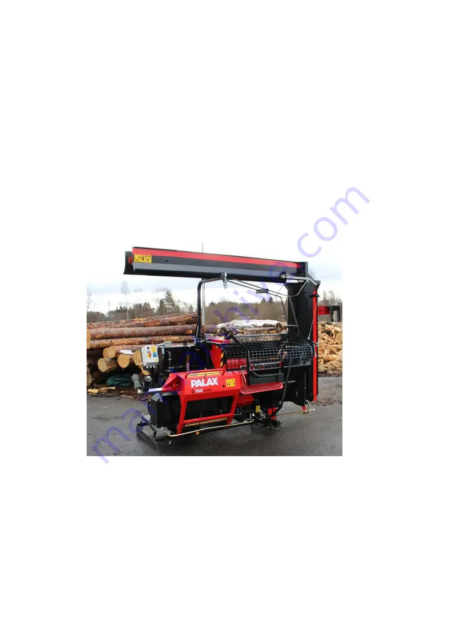
OPERATING INSTRUCTIONS 

PALAX C700 

COMBI 

powered by tractor 
powered by electricity 
powered by combustion engine 
swinging conveyor of 4.3-metres with hydraulic 
motor 


SERIAL NUMBER                                    _______________________ 
 
YEAR OF MANUFACTURE 

          _______________________ 

 
PALAX 
LAHDENTIE 9 
FI-61400 YLISTARO, FINLAND 
TEL.  +358 6 4745100 
 
WWW.PALAX.FI 

Summary of Contents for C700 COMBI

Page 1: ... tractor powered by electricity powered by combustion engine swinging conveyor of 4 3 metres with hydraulic motor SERIAL NUMBER _______________________ YEAR OF MANUFACTURE _______________________ PALAX LAHDENTIE 9 FI 61400 YLISTARO FINLAND TEL 358 6 4745100 WWW PALAX FI ...

Page 2: ...o the work position Figures 4 and 5 10 2 7 Bringing the conveyor into the transport position 11 2 8 Lifting and transferring the machine Figures 6A and 6B 12 3 DRIVING POWER 13 3 1 Powered by a tractor 13 3 2 Revolutions range of the PTO shaft 13 3 3 Stop switch of the tractor powered machine Figure 7 13 3 4 Automatic tightening of the V belts Figure 8 14 3 5 Required measures in an emergency situ...

Page 3: ...n Figure 21 23 6 5 Parts of the hydraulic valve Figure 22 23 6 6 Operation of the valve 23 7 Maintenance of the machine 24 7 1 Crosscut saw blade 24 7 1 1 Removing the crosscut saw blade Figures 23 and 24 24 7 1 2 Sharpening the chain 24 7 1 3 Stressing the saw blade 24 7 2 Guide for crosscut saw blade Figure 25 25 7 2 1 Adjustment of the saw blade guide 25 7 3 Automatic tightening of the angular ...

Page 4: ...1 2018 I V translation 8 Maintenance schedule 32 9 Malfunctions and their remedy 33 10 Electric diagrams 34 ...

Page 5: ...ne is expected to master the use of power take off shaft transmission Before the installation and operation the operator of the machine must become thoroughly familiar with the contents of the manual The operator is also obliged to gain familiarity with the operating controls of the machine and the emergency stop mechanism For more information about our products please visit our website at www pal...

Page 6: ...reby certify that the machine meets the requirements of the Government Decree 12 6 2008 400 on safety of machinery through which the Machine Directive 2006 42 EC has been put into effect and that during the manufacturing process the following harmonized standards have been applied SFS HANDBOOK 93 series SFS EN 349 1 A1 SFS EN 609 1 A1 SFS EN 618 SFS EN 847 1 A1 SFS EN 847 2 A1 SFS EN 847 3 SFS EN ...

Page 7: ...aximum diameter of the tree is about 25 cm The maximum length of the log to be processed is 4 metres If the logs are longer than this they must be pre cut to at most 4 metres 1 4 Warning signs Beware of the crosscut saw bar Read the instruction manual Lifting points Use eye guards and hearing protectors Wear clothes which do not hang loosely Wear safety shoes Use protective gloves Manual stop of t...

Page 8: ...on the serial number and year of manufacture when ordering spare parts Nameplates on the electric drive 3 phase motor Voltage 380 V Output 7 5 kW Hydraulic height adjustment of the splitting wedge optional Manual start of the splitting cylinder Stay away from moving partsof the machines Beware of PTO shaft Disconnect the machine from the electric supply before taking to any service measures The ma...

Page 9: ... position for transportation Always shift and lock the table extension into its rear position for transportation The three point linkage of the tractor is of size category two If using a tractor larger in size check that there is sufficiently space for the PTO shaft and its protective guard Never use the machine indoors risk of dust generation The use of a machine powered by combustion engine invo...

Page 10: ...ooked logs because as a result of faulty cutting the log might roll over or twist the saw bar with enough force to break it Keep the working space clean and clear of foreign objects Always stop the engine for refuelling Always stop the machine before servicing Only cut one log at a time Danger Stay away from moving parts Beware of the hot exhaust pipe on the combustion engine driven unit 1 8 Noise...

Page 11: ...f the combustion engine powered machine may involve danger of exhaust gases 1 11Terms of warranty The warranty period runs for 12 months from the date of purchase The warranty covers Parts damaged during normal operation of the machine due to defects in material or workmanship The reasonable repair cost in accordance with the agreement between the seller and the manufacturer or the buyer and the m...

Page 12: ...combustion engine and the winch Refer to the manuals on our website at www palax fi for detailed operating and servicing instructions for the combustion engine and the winch In matters related to the combustion engine turn to the nearest Honda dealer ...

Page 13: ...ck 4 Emergency stop 5 Manual start of the splitting cylinder 6 Disengaging clutch of the angular gear 7 Crosscut deck 8 Saw blade cover 9 Protective net for saw blade 10 Log stop control lever 11 Protective net for splitting chute 12 Adjustment lever 12 for the splitting wedge 13 Conveyor 1 1 2 3 4 5 6 7 8 9 10 11 12 13 Fig 1 Main parts of the machine Install protective net 9 as shown in Fig 1 so ...

Page 14: ...k is pushed forward the log stop folds completely away from the log 2 5 Topping up hydraulic oil Hydraulic oil volume 40 litres Oil type Univis 32 SHELL Tellus 32 NESTE HYDRAULI 32 or equivalent Only use fresh clean oil Observe particular cleanliness during the oil change because smooth operation of the machine is highly dependent on the purity of the oil 2 6 Bringing the conveyor into the work po...

Page 15: ...or 1 2 2 7 Bringing the conveyor into the transport position 1 Disconnect the attachment chain for the conveyor 2 Lower the conveyor to the ground and connect the support bar B for the conveyor chain Fig 5 3 Pull lock A open and lift up the conveyor top 4 Ensure that lock A is properly locked 5 Raise the conveyor using the winch 6 Tighten the winch wire lightly in order to prevent it uncoiling fro...

Page 16: ...the frame beams of the machine in the front or rear observing the centre of gravity of the machine By lifting points A at the upper part of the machine Fig 6A NOTE The machine must be equipped with appropriate lights and reflectors for transportation on public roads Fig 6B 9A A Fig 6A Lifting points of the machine 6B Fig 6B Example of additional lighting ...

Page 17: ... hook on the machine The machine comes with towing pins of 28 mm If the power take off of the tractor has a high speed range then it should be used because the horsepower requirement of the circular saw is small Make sure that the speed of the power take off shaft does not exceed 450 r p m 3 2 Revolutions range of the PTO shaft The suitable revolutions range is 400 450 r p m 3 3 Stop switch of the...

Page 18: ...ansmission of the tractor as well because the pulley of the angular gear can wear down the V belts unnecessarily NOTE When the clutch is reset to the operating position the power take off drive shaft must be disconnected from the tractor Only use the clutch in an emergency situation 3 6 Selecting the operating mode powered by tractor or electricity Figures 9 and 10 The machine is equipped with a s...

Page 19: ...l tens of seconds As the engine speed increases the D position is switched on and the motor quickly reaches full speed As the position D is switched on the signal light between the start and stop switches illuminates NOTE The machine must not be operated until the motor has reached full speed because in the Y position the output of the electric motor is very low 3 9 Emergency stop of an electric m...

Page 20: ...s lever to about half way activate the choke and pull the starter grip 3 As soon as the motor starts reduce the setting of the choke gradually to make the engine run smoothly 4 Switch on the V belt drive by shifting the clutch lever B and increasing the engine revolutions to maximum 5 The pre set engine revolutions are equal to about 2000 revolutions on the saw blade shaft 12 Fig 12 Clutch lever f...

Page 21: ...so makes the feeding process easier as the log stays on the rollers the maximum amount of time 4 2 Operating the crosscut saw before the operation Cleanse the new circular saw blade of any protective grease because a greasy blade accumulates resin easily making it heat up lose its tension and start to wobble 4 3 During the operation Exercise caution always keep your hands away from the saw blade N...

Page 22: ...here they bend When cutting crooked trees make sure that the log is properly supported by the rollers Big trees Make sure that the rotational speed of the saw blade is correct If the cutting sound is soft the cutting speed and the saw blade revolutions are correct If the cutting sound is loud and cracking the blade is proceeding too fast and the sawdust grooves get clogged Check the rotational spe...

Page 23: ...plit the force requirement immediately drops and the splitting motion resumes the high speed operation The automatic high speed valve speeds up processing of the firewood considerably and at the same time reduces the load on the transmission The automatic valve is also available for retro fitting 13 14 Fig 14 Automatic high speed valve 5 3 Splitting wedges Short straight wedge optional The short s...

Page 24: ... a flow regulation valve 5 6 Adjusting the speed of the splitting wedge adjustment cylinder Figure 17 A Flow regulation valve Adjustment The speed of the adjustment cylinder is increased by turning the valve A to the left NOTE Use as small a flow as possible as the diverted oil flow is lacking from the flow to the splitting cylinder A 14 B 15 Fig 15 Manual adjustment of the splitting wedge 15 16 F...

Page 25: ...ty devices affect the operation of the machine Figure 18 Stopping the splitting cylinder The machine does not operate unless the lock up device A for the splitting cylinder stopper is in the open position and the pedal B is not in the upper position Disengagement switch for the angular gear Keeping the V belts tight and the machine operational requires that disengagement switch C for the transmiss...

Page 26: ...Parts of the launch device Figure 20 1 Lock bar 2 Support bearing 3 Guide bearing 4 Safety wedge 5 Sensor 6 Adjustment sleeve 7 Launch bar 8 Limiter bearing 9 Control lever for manual start 10 Stroke limiter 6 3 Operational principle of launching 1 As the wood falls into the splitting chute it hits the tip of the sensor Figure 18 2 Sensor rod 5 Figure 20 lifts up launch rod 7 by means of the adjus...

Page 27: ...1 Tightener 2 Launch spring 3 Adjustment part of launch spring 4 Launch bar 5 Control lever 6 Locking lever of net cage 7 Detent end of valve 8 Valve 9 Spool shifter 10 Shaft 11 Launch bar 12 Locking lever for pedal 13 Locking lever spring 1 2 3 4 5 6 10 11 12 13 7 8 9 22 Fig 22 Parts of the hydraulic valve 6 6 Operation of the valve Tightener part 1 Stops and reverses the splitting cylinder stops...

Page 28: ...efore installing the blade make sure that the pin which prevents the saw blade from rotating is in place 23 A B Fig 23 Removing the crosscut saw blade 1 2 24 B A Fig 24 Removing the crosscut saw blade 2 2 7 1 2 Sharpening the chain The hard metal blade can be sharpened lightly using a diamond file Depending on the cleanliness of the wood as many as 5001000 bulk cubic metres of wood can be processe...

Page 29: ... nuts 7 3 Automatic tightening of the angular gear V belts Fig 26 The spring B draws the tightener from the slack side of the belts Then the belts automatically remain in correct tightness Belt type SPA 1382 2 pcs 7 4 Changing the V belts angular gear 1 Slacken the V belts using the emergency switch Figure 27 2 Remove the cover plates and the blade as instructed in point 7 1 3 Replace the old belt...

Page 30: ...chine lacks angular gear and related parts such as V belts belt tightener or emergency switch 7 6 Lubricating the machine Fig 28 If the machine is left unused for a longer period of time lubricate the shaft bearings A Figure 28 with roller bearing lubricant in accordance with the table at the end of the operating season NOTE If the machine is left standing for a longer period of time it is importa...

Page 31: ...ating hours or at least one year after the start of operations The oil plug is located in the outer corner of the tank bottom The filter must also be replaced because contaminants that end up in the filter are constantly extracted from the system 30 Fig 30 Oil tank 31 A B Fig 31 Valve 7 9 Maintenance of the valve To withstand and operate flawlessly the detent end A the spool shifter joint B and th...

Page 32: ...d with a pin and a ball joint that require regular maintenance and lubrication 1 Lift up the edge of the protective rubber of the spool shifter 2 Spray lubricant on both sides of the pin and down on the ball joint 3 At the same time check that the rubber is intact 33 Fig 33 Spool shifter 7 12Structure of the detent end and the correct order of the parts Fig 34 Keep cover C of the detent end depres...

Page 33: ...ol lever E In practice this does not affect the operation of the machine in any way If launch spring B Figure 35 is replaced adjustment part C must be installed in its original place The distance of the adjustment part from the end of the launch rod shall be about 105 mm 35 105 mm 3 4 mm A D E B C Fig 35 Basic settings of the valve 1 2 36 B n 34 mm Fig 36 Basic settings of the valve 2 2 NOTE Durin...

Page 34: ...lubricated daily The easiest way to do this is to apply chain spray lubricant to the chain while the conveyor is rotating at low speed The chain only requires light daily lubrication When the machine is left standing for longer periods it pays to lubricate the chain properly to prevent rust The sliding sleeves for the chain tighteners must also be lubricated lightly The bearings of the conveyor ar...

Page 35: ... longer period of time Lubricate the machine after washing Note Do not direct the water jet onto electric devices or bearings 7 19Storing the machine The machine is intended for outdoor use but it is recommended to keep it under cover for longer standstills to avoid corrosion or malfunctions For storing outdoors cover the machine with a tarpaulin of suitable size ...

Page 36: ...ons Check 1 Change 2 Change X X X Volume 40 l e g Esso Univis 32 Neste Hydrauli 32 Oil filter 1 Change 2 Change X X FIO 60 3 Blade shaft bearings Lubrication X Ball bearing lubricant Valve Lubrication X Lubrication oil spray All levers Lubrication X Lubrication oil V belts Angular gear Electric motor Combustion engine Check and change as necessary SPA 1382 2 pc SPA 1320 3 pc XPA 1332 3 pcs Crosscu...

Page 37: ...essing fault in the blade contact a professional The blade whines 1 Too high speed max 2000 r p m 2 Root crack at the tooth 1 Decrease the speed 2 Do not use replace the blade The saw blade rotates in the wrong direction 1 Wrong phase order 1 Switch the phase in the extension cord The electric motor does not start 1 Emergency stop button has been depressed 2 Makes loud noise but does not start 1 R...

Page 38: ...34 translation 10 ELECTRIC DIAGRAMS ...

Page 39: ...35 translation ...

Reviews: