Ormazabal CMS-17, General Instructions Manual
The Ormazabal CMS-17 General Instructions Manual is available for free download from manualshive.com. This comprehensive manual provides detailed guidance on how to properly use and maintain the CMS-17 product. Get your copy today and ensure you are getting the most out of your Ormazabal CMS-17 device.
Share
Download


Reviews:
No comments
Related manuals for CMS-17

isobar DL510PC
Brand: Tripp Lite Pages: 2

PM0816-01
Brand: Racktivity Pages: 25

CPD-1006L
Brand: Nady Systems Pages: 7

ETA-PD8A
Brand: ETA Systems Pages: 12
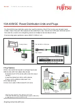
10A-400VDC
Brand: Fujitsu Pages: 2

IT-1 220
Brand: Furman Pages: 9

IS 4 CE RK
Brand: Torus Power Pages: 12

PDU3MV6L2120
Brand: Tripp Lite Pages: 3

AGPD7985
Brand: Tripp Lite Pages: 28

AG-003E
Brand: Tripp Lite Pages: 36

PSA-16A3S
Brand: Showgear Pages: 16

50667
Brand: Showgear Pages: 16

Amplink PDM
Brand: Rowe Pages: 8

48-11-2401
Brand: Milwaukee Pages: 20

SECURE PLUG 165-00471
Brand: MTI Pages: 12

Fairmont 42307
Brand: Greenlee Pages: 22


