Ohio Medical Area, Installation And Maintenance Manual
Discover the Ohio Medical Area product with our comprehensive Installation and Maintenance Manual. This manual is available for free download on our website, providing valuable information on how to properly install and maintain your Ohio Medical Area product. Get your manual today from manualshive.com and ensure your product's longevity.
Share
Download


Reviews:
No comments
Related manuals for Area
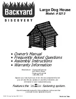
5213
Brand: Backyard Discovery Pages: 24

v.5 Pro
Brand: EarthPulse Pages: 7

hotSHOCK A50
Brand: Horizont Agrar Pages: 9

Cellu-Smooth
Brand: Beauty Works Pages: 8

W080
Brand: YachtSafe Pages: 4

SOLE RELIEF
Brand: Copper Fit Pages: 4

AIRCON WRIST SUPPORT
Brand: sensiplast Pages: 8

28 2F WOLFF
Brand: Perfect Sun Pages: 8

Kyroback
Brand: Radiancy Pages: 20

Home Relax MM9050F0
Brand: Rowenta Pages: 116

DOS190
Brand: Livoo Pages: 9

Focus 40 Blue
Brand: Freedom Scientific Pages: 55

CW12A0324
Brand: Coziwow Pages: 6

B-169 Series
Brand: Bobrick Pages: 2

shouldfix II
Brand: ORTHOSERVICE RO+TEN Pages: 13

84503
Brand: ORTHOSERVICE RO+TEN Pages: 36

Beauty Light
Brand: Lanaform Pages: 30

HydraSonic SSHS1
Brand: Satin Smooth Pages: 18


