IMPORTANT SAFETY INSTRUCTIONS
WARNING – TO REDUCE THE RISK OF FIRE, ELECTRIC SHOCK,
OR INJURY TO PERSONS, OBSERVE THE FOLLOWING:
1.
All electrical work must be done in accordance with local and/
or National Electrical Code as applicable. For safety, this prod-
uct must be grounded. If you are unfamiliar with methods of
installing electrical wiring, secure the services of a qualified
electrician.
2.
Turn off power at service entrance before installing wiring, ser-
vicing, or cleaning this product.
3.
Do not
install heater upside down or sideways. Heater must
be located in the horizontal position.
4.
Do not
recess louvered face of the heater more than three
inches from the vertical face of any overhang (cabinet).
5.
Do not
locate heater behind doors, furniture, etc., where the
air flow to the unit will be restricted.
6.
To avoid electrical shock;
do not
install heater within arm’s
length of tub or shower enclosure.
7.
To avoid motor bearing damage and noisy and/or unbalanced
impellers, keep drywall spray, construction dust, etc., off power
unit.
8.
Provide this heater with a separate electrical circuit following
directions under “Wire the Heater” section.
9.
This product is equipped with a thermostat which may start it
automatically. Turn off power at service entrance before clean-
ing or servicing.
10. This heater includes a visual alarm to warn that parts are get-
ting excessively hot. If the alarm lights are activated, immedi-
ately turn the heater off and inspect for any objects on or adja-
cent to the heater that may cause high temperatures.
11. Please read specification label on product for further informa-
tion and requirements.
INSTALLATION INSTRUCTIONS
READ & SAVE THESE INSTRUCTIONS!
Kickspace Heater
MODEL: 9114NT
PLAN THE INSTALLATION
This heater is designed for installation in an enclosed space such
as under a counter or kickspace to provide warm, gentle heat at the
floor level. Reread Safety Notes 3 through 8 for guidelines in plan-
ning the installation.
The Model 9114NT is factory wired for 240/208 V.A.C. operation. It
offers a choice of heat outputs and can be internally connected for
multiple wattages at different voltages shown in the table below.
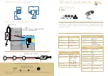
FIELD CONVERSION TO 120 V.A.C.
Refer to FIGURE 1
If a 120 V.A.C. circuit is to be used, make wiring changes as fol-
lows:
1.
Disconnect
white
wire from heater element terminal “2” and
connect it to terminal “4.” The heater will now operate at 120
V.A.C., 750W, 6.3A.
2.
For 120 V.A.C, 1500W, 12.5A operation, add the short
red
jumper wire (provided) between terminals “1” and “2”.
3.
Remove alarm light wire leads from terminals “1” and “3” of the
high temperature limit. Remove white wire lead from limit ter-
minal “1” and reconnect at limit terminal “3”. Secure wire leads
with wire tie so there is no interference with unit operation.
NOTE:
Terminal numbers are marked on the side of the blower
housing, above the heater elements.
VOLTS
WATTS
AMPS
BTU/HR
240
1500
6.3
5120
208
1125
5.4
3840
120*
1500
12.5
5120
120*
750
6.3
2560
All ratings are 1-Phase, 60 Hertz.
*See “FIELD CONVERSION TO 120 V.A.C.” section.
FIGURE 1