background image


MAN208  Rev Date 11/20/2014


VOPEX-C5USBVA-4 /-8 

VOPEX-C5USBVUA-4 /-8 

VGA Video/Audio  


Splitter/Extender 


Installation and Operation Manual 


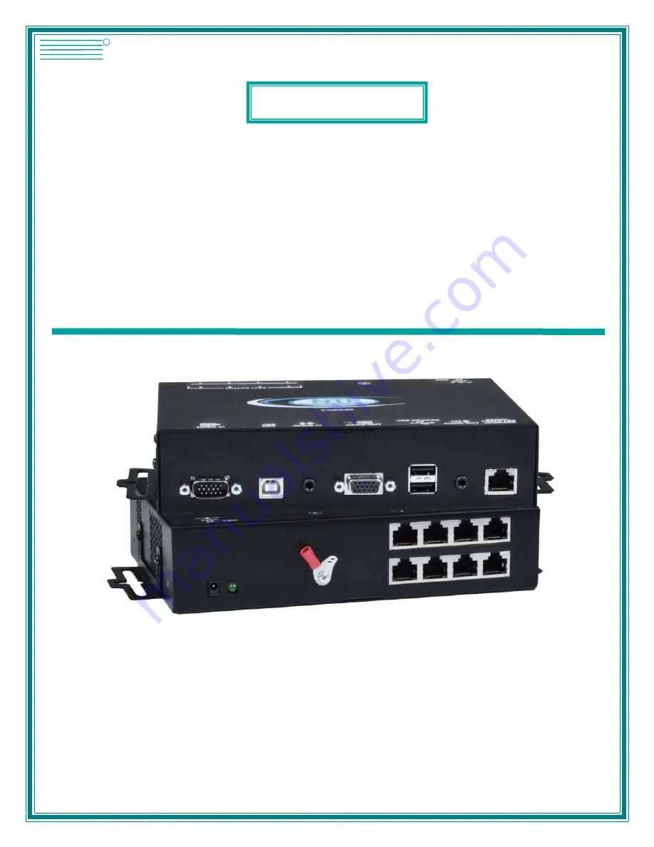
                                                                VOPEX-C5USBVUA-8 (Front and Rear View)                                           
 

VOPEX

®

Series


NETWORK
TECHNOLOGIES
INCORPORATED

Tel:330-562-7070
Fax:330-562-1999

1275 Danner Dr
Aurora, OH 44202

  www.networktechinc.com

NTI

R

Summary of Contents for VOPEX-C5USBVA-4

Page 1: ...SBVUA 4 8 VGA Video Audio Splitter Extender Installation and Operation Manual VOPEX C5USBVUA 8 Front and Rear View VOPEX Series NETWORK TECHNOLOGIES INCORPORATED Tel 330 562 7070 Fax 330 562 1999 1275 Danner Dr Aurora OH 44202 www networktechinc com NTI R ...

Page 2: ...sign without reservation and without notification to its users WARNING Never connect a VOPEX Series VOPEX C5USBV A 4 Extender Splitter to an Ethernet card Ethernet router hub or switch or other Ethernet RJ45 connector of an Ethernet device Damage to devices connected to the Ethernet may result Note CATx connection cable used between NTI VOPEX Series Splitter and XTENDEX Series Remote or any XTENDE...

Page 3: ...e to Upgrade the Firmware 14 Upgrade Procedures 15 Start the Bootloader 15 Upgrade the Local Controller Firmware 15 Upgrade the Local Port Controller Firmware 16 Upgrade the Remote Controller Firmware 16 Technical Specifications 18 Interconnection Cable Wiring Method 19 RJ45 Connector Wiring 19 Troubleshooting 19 Warranty Information 20 TABLE OF FIGURES Figure 1 Connecting the VOPEX to a PC 5 Figu...

Page 4: ...t is automatic for varying lengths of CATx cable Digital transmission of audio signals reduces any loss in quality Audio can be broadcast to self powered stereo speakers at each remote location and to the local unit MATERIALS Materials Included with this kit VOPEX C5USBV U A x x 4 or 8 for number of CATx ports 120VAC or 240VAC at 50 or 60Hz 5VDC 2 0A AC Adapter 4 Port or 3 0A AC Adapter 8 Port VEX...

Page 5: ...device 5 USB Devices USB Type A female for connecting any USB 2 0 full speed devices 6 Audio Out 3 5mm Stereo jack for connecting self powered stereo speakers 7 RS232 Firmware Upgrade RJ45 connector for connecting RS232 communication cable between the VOPEX and the RS232 port of a terminal VOPEX C5USBVUA 4 8 only 8 5VDC 2A Power Jack connection jack for the AC adapter 3A for 8 port model 9 Pwr Gre...

Page 6: ...ort is also present for touch screen monitor CAC reader or SMART Board for connection to any one of the 3 USB Type A ports 15 5VDC 3A Power Jack for connecting AC adapter to Remote Unit 16 Audio Out 3 5mm Stereo Jack for remote connection of self powered stereo speakers 17 CATx RJ45 Female for connecting the CATx cable between the VOPEX and Remote unit 17a Yellow LED traffic indicator illuminates ...

Page 7: ...ry to obtain male to male straight through connection cables long enough to reach from the wall outlets to the connection locations of the VOPEX and XTENDEX Remote Units A properly grounded polarized and preferably surge protected 120V or 240V electrical outlet depending on the AC adapter being used must be installed close enough to the connection location of the VOPEX and XTENDEX Remote Units mon...

Page 8: ...on the audio source Notes If all 3 connectors are available use the connector marked line out The line out connector is typically lime green and may be marked with this symbol The spkr connector is typically orange and may be marked with this symbol The headphones connector may be marked with this symbol c Connect the other 3 5mm stereo plug end of the SA 3 MM cable into the 3 5mm female stereo au...

Page 9: ...EX connection ports are provided on the VOPEX to support them The connections labeled USB DEVICES will support the connection of any USB 2 0 Low Speed or Full Speed rated devices not just the keyboard and mouse shown below An AUDIO OUT jack is provided for the connection of self powered stereo speakers Figure 2 Connect local devices as needed ...

Page 10: ... powered speakers where applicable to the 3 5mm female stereo connector on the Remote Unit 4 If the monitor is a USB connected touchscreen type connect the USB cable from the monitor to one of the USB Type A connectors labeled Supported USB Devices on the Remote Unit Supported on XTENDEX Remote model ST C5USBVUA R 1000 or ST C5USBVU R 1000 only Note The VOPEX must be model VOPEX C5USBVUA x to use ...

Page 11: ...ut on the VOPEX Connect the other end of that cable to the Cat x port on a Remote Unit When properly inserted the CATx cable end should snap into place Repeat for each Remote Unit installed WARNING Never connect the VOPEX to an Ethernet card Ethernet router hub or switch or other Ethernet RJ45 connector of an Ethernet device Damage to devices connected to the Ethernet may result Figure 4 Connect a...

Page 12: ...nnect the AC adapter to an XTENDEX Remote Unit 4 Connect the 5VDC 2 0A AC adapter power connector to the power port on the VOPEX 5VDC 3 0A on 8 port model 5 Plug the AC adapter into a power outlet The green LED on the VOPEX should illuminate indicating that a proper power connection has been made See Figure 6 Figure 6 Connect the AC adapter to a VOPEX 6 Turn ON the CPU stereo speakers and monitors...

Page 13: ...neously V Returns to General Video Quality Adjustment Mode from DDC Update Mode or Color Skew Adjustment Modes M Enable MAC Mode W Disable MAC Mode Esc Exits Command Mode Adjust Brightness The brightness of the extended image can be increased or decreased by pressing the Up Arrow or Down Arrow respectively while in Command Mode This adjustment is in addition to any adjustments made possible by con...

Page 14: ...h Command Mode provided the monitor is not changed Both the Local and Remote Units must be powered in order to update the DDC information The DDC information will be based on the monitors connected to the Remote Unit and locally at the VOPEX To update DDC information from Command Mode 1 press D to enter DDC Update mode See chart above for LED indications 2 press the Left Arrow Right Arrow keys sim...

Page 15: ...will illuminate 2 If a MAC CPU is connected press the M key The keyboard LEDs will momentarily flash and the MAC LED on the Remote Unit will illuminate to indicate MAC Mode is ON To reconnect the VOPEX to a SUN or Windows CPU the default setting press the W key and the MAC LED will go OFF Figure 7 MAC Mode LED Exit Command Mode Press the Esc key to exit Command Mode and return to normal operation ...

Page 16: ...sbv cpx x hex 3 Remote Controller the Remote Controller will be upgraded with a bin file named c5usbvu rcsx x bin The VOPEX firmware has a bootloader which can be used for firmware upgrades The bootloader resides in a protected area of Flash memory so that if the upgrade fails for any reason the bootloader will still be available to be used to re program the entire unit Upgrades are made to the Lo...

Page 17: ...the patch cable to the RS232 FIRMWARE UPGRADE port on the VOPEX attach the supplied 9DB to RJ45 adapter to the patch cable and connect the 9DB adapter to an available serial COM port on the PC Figure 8 Connect PC for firmware upgrade 2 Power ON the computer only Open the terminal console and apply the following settings to the terminal console for the port connected to the VOPEX Baud rate 57600 Da...

Page 18: ...firmware r R Upgrade Remote controller firmware s S Read Checksum of the Local port controller firmware Upgrade the Local Controller Firmware The Local controller firmware comes as a file in binary format and has the extension bin i e filename bin To upgrade the Local controller to this file press u from Terminal window The following message should appear on the screen Erasing flash memory Memory ...

Page 19: ...oader press x Note The Local port controller firmware will rarely if ever need to be updated The firmware download package will include both of the current Local and Remote controller firmware versions but will only include the Local port controller firmware if it has changed Upgrade the Remote Controller Firmware Note To upgrade the Remote Controller firmware the Remote Unit must be connected to ...

Page 20: ...nu Bar of the HyperTerminal window 2 click the item Send File 3 in the dialog box which pops up on the screen browse for the file to be sent and select it 4 select Xmodem from the Protocol drop down menu 5 press Send button The transmission will start shortly Wait until the transmission is finished There will be some pauses during transmission since the processor writes blocks of 4KB When the tran...

Page 21: ... A x 4 Port Power 8 Port Power 120V or 240V at 50 or 60Hz 5VDC 2 0A via AC Adapter 120V or 240V at 50 or 60Hz 5VDC 3 0A via AC Adapter Remote Unit Power 120V or 240V at 50 or 60Hz 5VDC 3 0A via AC Adapter AC Adapter Power Connector 1 3X3 5mm connector center positive Storage temperature 20 to 140 F 30 to 60 C Operating Temperature Range 32 F to 100 F 0 C to 38 C VOPEX Size In WxDxH VOPEX C5USBV U ...

Page 22: ...stions that arise If the answer is not found in the chart a solution may be found in the knowledgebase on our website at http information networktechinc com jive kbindex jspa or please call us directly at 800 742 8324 800 RGB TECH or 330 562 7070 and we will be happy to assist in any way we can Problem Cause Solution VOPEX power LED does not illuminate Power supply is not connected or plugged in M...

Page 23: ...ected Check all cable connections Verify speakers are powered if applicable Check CATx cable connections USB doesn t does not work after power cycling VOPEX or hot plugging the USB on the VOPEX The CPU may take a minute or more to re recognize the VOPEX after a hot plug or power cycle Wait at least a minute or two to give the CPU opportunity to refresh its connection with the VOPEX WARRANTY INFORM...

Reviews: