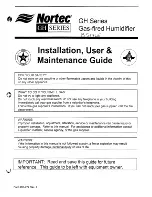
background image

Summary of Contents for Gas-fired Humidifier

Page 1: ...ollow the gas supplier s instructions If you can not reach your gas supplier call the fire department WARNING Improper installation adjustment alteration service or maintenance can cause injury or property damage Refer to this manual For assistance or additional information consuU a qualified installer service agency or the gas supplier WARNING If the information in this manual is not followed exa...

Page 2: ...T 8 ADDITIONAL REQUIREMENTS WHEN VENTING THROUGH A SIDEWALL 8 ELECTRICAL 8 PRIMARY WIRING 8 LOW VOLTAGE CONTROL WIRING 9 CONTROL INSTALLATION 10 BLOWER PACKS 10 STEAM DISTRIBUTORS FOR DUCTED APPLICATIONS 10 PLUMBING 12 WATER SUPPLY LINE 12 DRAIN LINE 13 STEAM LINE 13 WATER TRAP 14 CONDENSATE RETURN LINES FOR STEAM DISTRIBUTORS OPERATION WATER LEVEL CONTROL 14 15 15 BAND P MODELS 15 MC MODEL 15 SEQ...

Page 3: ...ACEMENT 19 TRANSFORMER REPLACEMENT 19 AIR SWITCH REPLACEMENT 19 COMBUSTION AIR BLOWER REPLACEMENT 20 TANK REPLACEMENT 20 HEAT EXCHANGER REPLACEMENT 20 SERVICING THE UNIT 21 FAULT CONDITIONS 21 BAND P MODELS 21 MC MODELS 21 SERVICE CHECKS 21 FLAME SENSOR 21 IGNITER CHECK 21 GAS VALVE SETTING 21 PREVENTATIVE MAINTENANCE SCHEDULE 23 START UP AND INSPECTION 24 TROUBLESHOOTING GUIDE 25 REPLACEMENT PART...

Page 4: ...t for damage and if damage is found notify the shipper promptly 5 All NORTEC products are shipped on an F O B factory basis Any and all damage breakage or loss claims are to be made directly to the shipping company 1 GENERAL SPECIFICATIONS The NORTEC GH Series humidifier is a completely new patented design based on leading edge technology The GH is designed to provide clean steam humidification at...

Page 5: ... LBS LBS STO ov OV NATURAL 357 000 357 000 300 0 2 0 00 1 062 800 1200 178 000 255 000 210 0 2 0 00 1 062 GAS 65 000 85 000 70 0 2 0 00 1 062 357 000 357 000 0 00 1 062 800 1200 1t For high altitude units 2000 4500 ft the input and steam capacities are de rated by 10 STD Standard Gas Unit DV Direct Vent Unit MODEL GH 400 SPECIFICATIONS FUEL BLOWER INPUT BTUH STEAM CAPACITY MANIFOLD PRESS IN AIR OP...

Page 6: ...ng legs must be left in place when floor mounted on combustible material The humidifier shall not be installed directly on carpeting tile or other combustible material other than wood flooring 8 For recommended clearances for servicing refer to Figure 2 3 9 During installation cover the humidifier to prevent any dust or other contaminants from entering the cabinet when activities such as drilling ...

Page 7: ...Factory approval is needed Removal or adjustment of legs requires the square end of a 3 8 socket driver 10 Optional stands are available for all GH Series humidifiers Refer to Shop Drawing Package Form 273 for details and part numbers 15 Clearances around the unit should also be maintained for good access the gas humidifier 3 feet clearance is needed on the right side of the enclosure for GH100 20...

Page 8: ...ow this procedure may damage the gas valve Over pressured gas valves are not covered by warranty 2 DO NOT use Teflon tape on gas line pipe threads A flexible sealant suitable for use with Natural Gas and Propane Gas is recommended 3 Plan gas supply piping so it will not interfere with removal of gas valves or blower assemblies and front or side service doors The gas valve is provided with pressure...

Page 9: ...c_t______ 1 Z Flex I Z Flex Aluminum Chim I Iney Liner II Flex L International_l ll iner ___ i i I i I IMICHIGAN CHIM FLEX CHIM FLEX Aluminum III Liner i il i T I _ I e I b o c o o o o o c c Jj The following table details the allowable duct length that can be connected to the direct vent option Each 90 degree elbow equals 10ft and each 45 degree elbow equals Sft If flexible vent material is used a...

Page 10: ...er vent sequencing Consult with venting contractor supplier for proper hook up Contact NORTEC for additional information GH100 units are supplied with a 90 degree elbow female to female for the vent connection This elbow has the correct dimensions to align the venting with the knock outs in the top and rear cabinet panels The installed venting can be connected to this elbow as long as a proper sea...

Page 11: ...the humidifier NOTE OUTDOOR ENCLOSURE Flue gases must be vented out of the enclosure 8 ADDITIONAL REQUIREMENTS WHEN VENTING THROUGH A SIDEWALL For sidewall venting locate the humidifier as close as possible to the wall being used Locate the vent terminal at least three feet above any forced air inlet located within ten feet or at least four feet below four feet horizontally from or one foot above ...

Page 12: ...afety setpoint Set to approximately 85 RH as a safety to prevent saturation and wetting in the duct Highly recommended for ducted applications C Duct Mounted Safety Air Proving On Off Switch Wired to make when sensing air flow break when no air flow Used as a safety to prevent saturation when there is no air flow Highly recommended for ducted applications D E Wall or Duct Mounted Modulating Humidi...

Page 13: ...before starting humidifier 6 Calibration of controls on off or modulation in the field may be necessary due to shipping and handling Verify humidistat accuracy before commissioning system BLOWER PACKS 1 Blower packs are an optional accessory used to directly distribute steam to localized areas such as computer rooms or in structures that 10 do not have a built in air distribution system Blowers ar...

Page 14: ...pward or downward slope to the distributor will result in poor condensate drainage and spitting of condensate in duct See Figure 10 Figure 10 I I 1 I Always Mount Level 1 J 1 Any distributor longer than 3 feet 1 meter should be supported at its end with a threaded 11 rod through top or bottom of duct See Figure 11 Figure 11 3 8 Ttveaded lbd Field SuWied Duct Steam DiStlibutor Hex Nut Factory SuWli...

Page 15: ... valve s small flow regulating orifice could become plugged 3 Consider using a water softener Longer operating times between tank cleaning will be reached on softened water 4 Reverse osmosis RO water can provide very long times before cleaning is required since it is cleaner than softened water However it is also more corrosive Consult factory before using Deionized 01 water may be used with speci...

Page 16: ...nd cause backup The drain line should be 1 0 0 copper pipe or larger Do not use plastic pipe for drain lines Consult factory NOTE FOR OUTDOOR ENCLOSURE Humidifier must not be drained on the roof If freezing condition occur drain lines should be heat traced STEAM LINE 1 Field supplied hard copper with thick min insulation is recommended for steam supply with NORTEC supplied steam hose coupling used...

Page 17: ...arest drain lower than the distributor See Figure 22 10 Do not run steam line more than 1 foot per Ib hr output Example 10 Ibs hr should not have a steam run longer than 10 feet If long runs are unavoidable the humidifier should be sized larger to compensate for condensate 14 Figure 22 er AF Lew Poinl10 R_ Wh__ n Steam Un Al f roac ft The o buDf From Abo losses and insulated copper should definite...

Page 18: ...ing sequence The water fill continues until float A is reached Float A will initiate a variable time delay relay which maintains water flow for a preset amount of time During a portion of this time the water level in the tank will exceed the level of the blowdown and water will flow down the drain until the timed cycle is complete During operation the water level in the tank will lower by evaporat...

Page 19: ...l shut off and this cycle will be repeated a maximum of three times When the humidity in the space matches the setting of the operating controller the burners will shut down and the unit will remain idle until the next call for humidity SLOWDOWN CALIBRATION The gas humidifier will periodically blowdown or skim water from the tan k to reduce the concentration of total dissolved solids that accumUla...

Page 20: ...lues GHMC DISPLAY OPERATION Refer to the GHMC Display Unit Operating Instructions Form XX 274 for information on programming and operating the display unit START UP PROCEDURE Also see Startup Sheet on page 21 17 Prior to filling the unit it is necessary to ensure that no dirt or dust has accumulated in the control compartment If necessary clean this area to prevent contaminants from being drawn in...

Page 21: ...atch the stainless steel surfaces of the tank Once all large pieces of scale have been removed vacuum the tank out with a shop vacuum fill part way with water and flush remaining sediment from the tank through the drain 18 Due to the presence of polymer gaskets around the heat exchangers do not use any harsh cleaning chemicals Please consult NORTEC prior to using any chemicals Once the lid has bee...

Page 22: ... from the gas supply manifold 7 Remove union and nipple assembly from valve that is being replaced and install on new valve 8 Reverse above procedure to reinstall J 9 Leak test the gas train before re commissioning unit 19 Hot Surface Igniter Replacement NOTE Replacement igniters must be supplied by NORTEC or damage to the unit may occur 1 Shut off electrical power and gas supply to the appliance ...

Page 23: ...e knobs 6 Remove left door panel 7 Disconnect float chamber by uncoupling the union and releasing the hose clamp 8 Disconnect the blowdown skimmer line 3 4 copper utilizing the union 20 9 Remove gas manifold by disconnecting the coupling bellow the gas valve 10 Remove exhaust manifold from GH200 GH 300 or GH400 only 11 Remove nuts holding the heat exchanger And pull heat exchanger out Do not remov...

Page 24: ...he reset button on the main MC control board mounted on the Electrical Swing Panel inside the electrical cabinet 21 II LEO Indication I Error Mode i i__________________ Ii Internal Control Failure 11 _ _ _ _ _ _ __ i Air Flow Fault Steady on 1 Flash I Flame With No Call For Heat I2 Flashes SERVICE CHECKS Flame Sensor Flame current is the current which passes through the flame from the sensor to gr...

Page 25: ...ions This table should be used as a guide when servicing troubleshooting the unit The actual measured manifold pressure should fall within the range shown Maximum Vent Minimum Vent Length length 70 ft 21m Maximum firing 0 62 W c 0 40 W c rate Minimum firing 0 25 W c 0 15 w c rate 22 ...

Page 26: ...hamber X X X Ensure floats move freely Clean scale from chamber when required Fill Lines X X X Inspect for leaks Drain Lines X X X Inspect for leaks at the drain pump fillcup and the float chamber Gas Venting X X X Inspect for leaks Inspect terminal cap is clear flue temp 350 400 Direct Vent X X Inspect for leaks Inspect intake terminal clear Gas Burner X Clean with compressed air from outside mat...

Page 27: ... Tum unit ON at the main power switch Unit will fill automatically until low water float is reached and trial for ignition will begin After 3 tries the ignition module will lockout since gas valve is turned OFF Wait until fill sequence is completed Tum unit OFF at the main power switch Manually tum all gas valve to the ON position red switch 2 Testjng the ignition safety Shut OFF Manually close Ga...

Page 28: ...ight MC display for failure identification See Fault Conditions for identification of fault codes Loose wire s Check wiring connection s No call for humidity Defective or loose blower driver board Check blower driver board for green LED Check if properly seated Replace if properly seated but no LED Defective blower Replace blower 24VDC power supply defective or fuse blown Check fuse on power suppl...

Page 29: ...N Q c Q 27 J t Nortec WHEN YOU NEED HUMIDITY 24 REPLACEMENT PARtS GH Series 10 ...

Page 30: ... GHMC 170 1804 170 1804 170 1804 170 1804 I Valve Solenoid 2 way 24Vac SST GHMC 170 4207 170 4207 170 4207 170 4207 I I 11 Float Chamber Body all models 170 5074 170 5074 170 5074 170 5074 I 12 Ignition Module Main Burner A only GHB GHP 170 2501 170 2501 170 2501 170 2501 I i all Burners GHMC 170 2502 170 2502 170 2502 170 2502 i Ignition Module Auxiliary Burners B C D GHB GHP nla 170 2502 170 250...

Page 31: ...N co 20 21 dNrftrte J4 eP VI WHEN YOU NEED HUMIDITY 9 REPLACEMENT PARTS GH Series 16 ...

Page 32: ...all models 170 7996 170 7996 170 7996 170 7996 21 Controller Base GHB GHP 170 3041 170 3056 170 3081 170 3081 Controller Base GHMC 170 3600 170 3600 170 3600 170 3600 22 Blower Driver all models 170 3604 170 3604 170 3604 170 3604 23a Interface Panel Assemblv Complete GHB GHP 170 1313 170 1322 170 1342 170 1342 Electrical Interface panel GHB GHP 170 7990 170 7991 170 7992 170 7992 Potentiometer 10...

Page 33: ...3 8 ALL ABOVE TYPICAL X 24 j 7 1I1ortec WHEN YOU NEED HUMIDITY T GH 100 GH 200 GH 3001400 H L MODEL DIMENSION L W H in em In em in em 12 6 32 26 4 67 30 0 77 20 3 52 23 6 61 30 0 77 36 7 94 23 6 61 30 0 77 GH STANDS Assembly November 6 2000 ...

Page 34: ...others 3 See GH Shop Drawings for dimensions locating vent fill drain steam and gas connections 4 As a standard the GH unit is factory mounted inside the enclosure 5 Steam lines should be routed through the back or sides of the enclosure 6 Insulate and minimze steam run length to reduce steam losses 7 If freezing conditions occur enclosure should be used in conjunction with freeze proction feature...

Page 35: ...IN BEAM o Nortec 4 r WHEN YOU NEED HUMIDITY RUBBER GASKET DETAIL A INSERT RUBBER GASKET PROVIDED ONTO MOUNTING STUD THEN INSTALL THE HEATER THROUGH THE HOLE IN THE HANDLE PLACE THE WASHER AND SECURE INSTALLATION WITH THE NUT GH ECLOSURE Heater Installation instructions DWG 1502303 ...

Page 36: ...onnector 4 Air Manifold J 5 Clamp Gear DIRECT VENT Nortec PIN GH100 GH200 GH300 150 1635 150 1635 i 150 1635 150 2164 150 2164 150 2164 150 2148 150 2148 150 2148 150 2030 150 2029 150 2320 132 5009 132 5009 132 5009 33 1 5 3 4 GH400 150 1635 150 2164 150 2148 150 1634 132 5009 ...

Page 37: ...OFF By others ON OFF Controls in series i J L ON OFF Controls in series i _ I t e e _ _l _____ _ 1 6 1I el l1 r 2 1 IWul II WHEN YOU NEED HUMIDITY 34 0 10 Vde Modulating Humidistat By Others Wall Or Duct GH SIP Wiring Diagram ...

Page 38: ...ld permanently damage the electron ics Such errors wi 11 void the unit warranty Modulation Signal Input An GHP MC Peripheral Humidifier Interface 0 10 Vdc Unit Operation Signal BMS Interface 0 10Vdc 5 Vdc Supply Modulation Signal Input 8 MC Only EXTERNAL I r l y a r I _ __ _ EXTERNAL 718 9 1 10111 12 1 INTERNAL NOTE If no On Off Control is used then a field jumper must be connected across terminal...

Page 39: ...LEXMASTER CANADA LIMITED Delta BC 7350 72ND Street 124 V4G 1H9 Telephone 604 940 6401 Fax 604 940 6402 NOTE Venting to be used with Direct Vent units FLEXMASTER CANADA LIMITED Calgary ALTA 208 39TH Avenue NE T2E 2M5 Telephone 403 277 3115 Fax 403 276 1309 FLEXMASTER CANADA LIMITED Etobicoke ON 452 Attwell Drive M9W 5C3 Telephone 416 679 0045 Fax 416 679 0051 FLEXMASTER CANADA LIMITED HEAD OFFICE R...

Page 40: ...es expressed or implied by law No liability whatsoever shall be attached to THE COMPANY until said products have been paid for in full and then said liability shall be limited to the original purchase price for the product Any further warranty must be in writing signed by an officer of THE COMPANY THE COMPANY s limited warranty on accessories not of NORTEC s manufacture such as controls humidistat...

Page 41: ...TRIES INC P O Box 698 826 Proctor Avenue Ogdensburg NY 13669 Website www humidity com ortec SERIES I NORTEC AIR CONDITIONING INDUSTRIES LTD 2740 Fenton Road Ottawa ON K1T 3T7 E mail sales humidity com A WMH COMPANY ...

Reviews: