background image

ENGLISH

For the latest Parts manuals and other
language Operator manuals, visit:

www.nobles.com/manuals

®

9015513

Rev. 03 (09-2020)

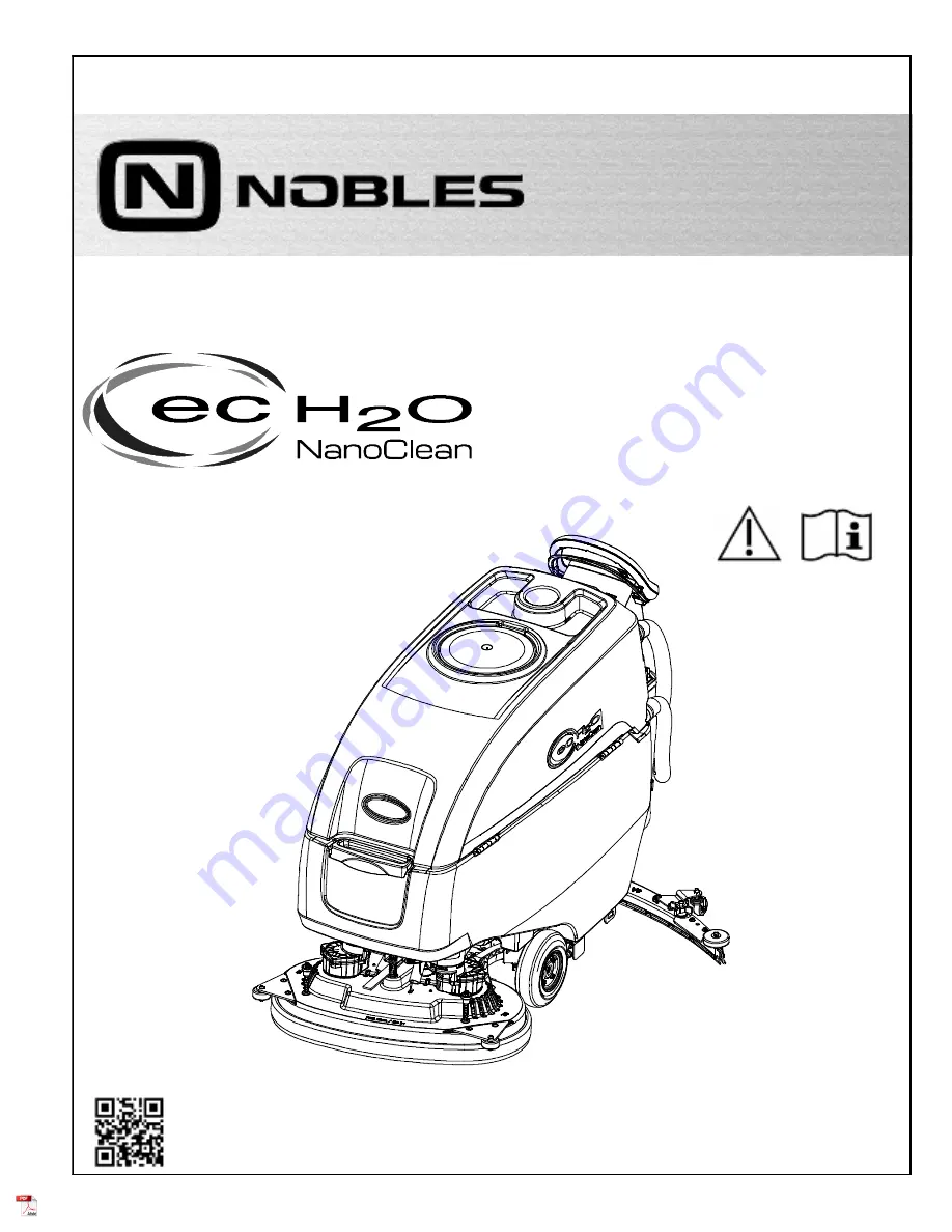
WALK-BEHIND FLOOR SCRUBBER

*9015513*

®

OPERATOR MANUAL

SPEED SCRUB 500

R

Tennant

True

®

Parts

IRIS

®

a Tennant Technology

Insta-Fit

™ Adapter

Smart-Fill

™ Automatic Battery Watering

Summary of Contents for SPEED SCRUB 500

Page 1: ... language Operator manuals visit www nobles com manuals 9015513 Rev 03 09 2020 WALK BEHIND FLOOR SCRUBBER 9015513 OPERATOR MANUAL SPEED SCRUB 500 R TennantTrue Parts IRIS a Tennant Technology Insta Fit Adapter Smart Fill Automatic Battery Watering ...

Page 2: ...and parts are subject to change without notice Original Instructions Copyright 2017 2020 Tennant Company All rights reserved INTENDED USE The Speed Scrub 500 walk behind floor scrubber is intended for commercial use for example in hotels schools hospitals factories shops offices and rental businesses It is designed to scrub hard floor surfaces concrete tile stone synthetic etc in an indoor environ...

Page 3: ...NDICATOR Option 17 MACHINE OPERATION 18 PRE OPERATION CHECK LIST 18 OPERATING MACHINE 18 EMERGENCY SHUT OFF BUTTON 19 WHILE OPERATING MACHINE 19 CIRCUIT BREAKER PANEL 20 HOUR METER 20 DRAINING TANKS 20 DRAINING RECOVERY TANK 20 DRAINING SOLUTION TANK 21 SERVICE INDICATOR CODES 22 ON BOARD BATTERY CHARGER SERVICE INDICATOR CODES 23 ec H2O SYSTEM SERVICE INDICATOR CODES OPTION 23 MAINTENANCE MAINTEN...

Page 4: ...CONTENTS 4 Nobles Speed Scrub 500 01 2017 ...

Page 5: ...h defects or other reproductive harm IRIS Telemetry This machine may be equipped with technology that automatically communicates over the cellular network If the machine will be operated where cell phone use is restricted because of concerns related to equipment interference please contact a Tennant representative for information on how to disable the cellular communication functionality FOR SAFET...

Page 6: ...e incompatible battery chargers as this may damage battery packs and potentially cause a fire hazard Inspect charger cord regularly for damage Keep work area well ventilated Avoid contact with battery acid Keep all metal objects off batteries Do not power spray or hose off machine Electrical malfunction may occur Use damp cloth Use a hoist or adequate assistance when lifting batteries Battery inst...

Page 7: ...e WARNING LABEL Located on recovery tank cover WARNING LABEL Electrical hazard Disconnect battery cables before servicing machine Located on circuit breaker panel WARNING LABEL Batteries emit hydrogen gas Explosion or fire can result Keep sparks and open flame away when charging Located on bottom side of recovery tank WARNING LABEL Spinning brush Keep hands away Located on scrub head ...

Page 8: ...OPERATION 8 Nobles Speed Scrub 500 09 2020 MACHINE COMPONENTS 23 24 29 31 32 33 20 30 34 35 27 25 26 13 5 4 2 12 11 7 6 9 10 8 17 36 37 28 19 22 21 20 1 3 18 15 16 14 ...

Page 9: ...harger cord 18 Off board battery charger receptacle 19 Squeegee lower lift foot pedal 20 Squeegee assembly 21 Squeegee vacuum hose 22 Squeegee debris drip tray 23 Recovery tank 24 ec H2O module option 25 ec H2O water conditioning cartridge 26 Battery compartment 27 Automatic battery watering tank option 28 Solution tank 29 Solution tank front bucket fill port 30 Scrub head 31 Scrub head skirt 32 P...

Page 10: ...dicator 7 Battery discharge indicator BDI 8 ec H2O indicator option 9 Automatic battery watering indicator option MACHINE SYMBOLS ec H2O scrubbing option Circuit breaker No detergent ec H2O option Water temperature ec H2O option Battery charge Fast speed drive model Slow speed drive model Parking brake Forward Reverse drive model Key On Key Off Automatic Battery Watering Tank Option Read Manual Do...

Page 11: ...R SETTINGS ATTENTION Do not disconnect battery cables while charger is plugged in circuit board damage may result IRIS Battery Charging Metrics Notification Machines equipped with capability to report battery charging data via IRIS are supplied with a charger and set of batteries from the factory When a battery reaches its end of life and must be replaced Tennant highly recommends that the same ba...

Page 12: ...to maintain highly polished or burnished floors Buffing pad Red Used for light duty scrubbing without removing floor finish Scrubbing pad Blue Used for medium to heavy duty scrubbing Removes dirt spills and scuffs and leaves surface clean ready for re coating Stripping pad Brown Used for stripping of floor finish to prepare the floor for recoating Heavy duty stripping pad Black Used for aggressive...

Page 13: ...ing brake if equipped 2 Attach the pad to the pad driver before installing the driver Secure pad with center lock Figure 9 FIG 9 FOR SAFETY Do not operate machine with pads or accessories not supplied or approved by Tennant The use of other pads may impair safety 3 Set the yellow spring clips to the open position to make brush installation easier Press clips down and outward to set Figure 10 FIG 1...

Page 14: ...nnant The use of other pads may impair safety 2 Attach backer pad retaining strips facing downward to working pad Figure 14 FIG 14 3 Attach the two pads to the bottom of the scrub head Figure 15 Make sure pad is centered on scrub head FIG 15 INSTALLING CYLINDRICAL BRUSHES Cylindrical Brush Scrub Head Model 1 Raise scrub head off floor and remove key FOR SAFETY Before leaving or servicing machine s...

Page 15: ...roved cleaning detergents Machine damage due to improper detergent usage will void the manufacturer s warranty WARNING Flammable materials can cause an explosion or fire Do not use flammable materials in tank s NOTE Do not use the ec H2O system when there are conventional cleaning detergents in the solution tank Drain rinse and refill the solution tank with clear cool water before operating the ec...

Page 16: ...re date The shelf life of an un installed cartridge is one year from manufacture date For new cartridge replacement the ec H2O module timer must be reset See ec H2O WATER CONDITIONING CARTRIDGE REPLACEMENT ATTENTION During first time use and after replacing the water conditioning cartridge the ec H2O system will automatically override the selected solution flow rate for up to 75 minutes CONTROL PA...

Page 17: ...so flash a fault code See SERVICE INDICATOR CODES to diagnose machine fault FIG 31 BATTERY DISCHARGE INDICATOR The battery discharge indicator BDI displays the charge level of the batteries while the machine is operating When the batteries are fully charged all five indicators are lit Figure 32 When the discharge level reaches the red light stop scrubbing and recharge the batteries When the red li...

Page 18: ...equipped Figure 34 2 Turn the key to the on I position Figure 34 FIG 34 3 ec H2O models The ec H2O system will automatically turn on at key start up The ec H2O indicator will appear on the control panel indicating that the system is activated Figure 35 ATTENTION When conventional scrubbing with cleaning detergents in solution tank make sure to turn off the ec H2O system by pressing the ec H2O swit...

Page 19: ...RNING Flammable materials or reactive metals can cause an explosion or fire Do not pick up 1 Overlap each scrub path by 2 inches 5 cm 2 Keep machine moving to prevent damage to floor finish 3 Wipe squeegee blades with a cloth if blades leave streaks 4 Avoid bumping the machine into posts and walls 5 When draining and refilling machine always top off the optional Severe Environment tank with deterg...

Page 20: ... CB2 10 A ec H2O system automatic battery watering system CB3 10 A Scrub head lift actuator CB4 20 A Vacuum motor CB5 25 A Left brush motor CB6 25 A Right brush motor CB7 60 A Propel FOR SAFETY When servicing machine all repairs must be performed by trained personnel HOUR METER The hour meter records the number of hours the machine has been operated Use the hour meter to perform specific maintenan...

Page 21: ...icing machine stop on level surface turn off machine remove key and set parking brake if equipped 2 To drain remaining water from solution tank pull the solution tank level hose from the accessory rail Figure 48 Firmly reconnect the hose to the accessory rail after draining tank FIG 48 3 Rinse solution tank with clean water Figure 49 FIG 49 4 Remove the solution tank filter and clean screen after ...

Page 22: ...ontrol board problem Contact service S S S Propel circuit breaker tripped Reset circuit breaker If fault repeats contact service S S Propel motor wiring connector or control board problem Contact service S S S Propel faults Restart machine If fault repeats contact ser vice S S S Battery watering pump wiring connector or control board problem Contact service S S Brush motor relay short fault Check ...

Page 23: ...lashing LED fault code Solid or blinking Red ec H2O indicator LED Fault Code Flashing CAUSE SOLUTION S S S ec H2O pump wiring connector or control board problem Contact service S ec H2O pump over current Contact service S S S ec H2O system breaker tripped ec H2O pump breaker tripped Reset circuit breaker If trip repeats contact service ecH2O indicator solid red ec H2O electrical fault Contact serv...

Page 24: ...gh Clean O 9 Scrub head skirt Check for damage and wear Weekly O 7 Battery cells Check electrolyte level O 6 Squeegee assembly drip trap reservoir Check clean 50 Hours O 2 Cylindrical brushes Rotate brushes Check for wear O 2 Cylindrical scrub head Clean underside of scrub head O 3 Recovery tank lid seal Check for wear O 10 Solution tank filter Remove and clean 100 Hours O 7 Battery watering syste...

Page 25: ...ipment as needed All repairs must be performed by trained personnel AFTER DAILY USE 1 Drain and rinse out the recovery tank Figure 51 See DRAINING TANKS FIG 51 2 Remove and clean the float shut off screen Figure 52 FIG 52 3 Drain and rinse out the solution tank Figure 53 FIG 53 4 Disk scrub head Turn pad over or replace when worn Figure 54 FIG 54 5 Replace brushes when they no longer clean effecti...

Page 26: ...hine with an all purpose cleaner and damp cloth Figure 59 FOR SAFETY When servicing machine do not power spray or hose off machine Electrical malfunction may occur Use damp cloth FIG 59 9 Cylindrical brush scrub head Remove and clean debris trough Figure 60 FIG 60 10 Automatic battery watering option Refill tank with distilled water Figure 61 Replace cap FIG 61 11 Charge batteries Figure 62 See BA...

Page 27: ...5 Turn the filter bowl counter clockwise to remove FIG 65 2 Cylindrical brushes Rotate brushes from front to rear Figure 66 Replace brushes when they no longer clean effectively FIG 66 3 Cylindrical scrub head Remove debris buildup from underside of scrub head including the idler plates and drive hubs Figure 67 FIG 67 AFTER EVERY 100 HOURS OF USE If machine is equipped with the optional battery wa...

Page 28: ...ent Hours Vacuum motor 750 Propel motor 1250 Disk brush motors 1250 Cylindrical brush motors 1250 Orbital brush motor 1250 BELTS Cylindrical Brush Model FOR SAFETY Before leaving or servicing machine stop on level surface turn off machine remove key and set parking brake if equipped Replace belts every 1250 hours Contact trained personnel for belt replacement Figure 69 FIG 69 ...

Page 29: ...looded wet lead acid batteries require routine watering as described below Check the battery electrolyte level weekly NOTE If machine is equipped with the automatic or manual battery watering system proceed to the BATTERY WATERING SYSYEM instructions The electrolyte level should be slightly above the battery plates as shown before charging Figure 70 Add distilled water if low DO NOT OVERFILL The e...

Page 30: ...harger s power cord from the storage hooks and plug power cord into a properly grounded wall outlet Figure 72 FIG 72 For models equipped with off board chargers first connect the charger s DC cord into the machine s battery charge receptacle then plug the AC power supply cord into a properly grounded wall outlet Figure 73 Refer to the off board battery charger s owner manual for operating instruct...

Page 31: ...be manually changed See CHANGING ON BOARD BATTERY CHARGER SETTINGS The battery discharge indicator will automatically reprogram to match battery type when the battery charger profile is changed NOTE TPPL batteries come with an unique battery charger that is only used with TPPL batteries It s not intended to be changed CHANGING ON BOARD BATTERY CHARGER SETTINGS To manually change the on board batte...

Page 32: ...teries before charging the electrolyte level will expand and may overflow when charging 2 After charging batteries check the battery electrolyte level indicators located on the battery covers Figure 79 If the level indicator is black add water as described in the following instructions If the level indicators are white the electrolyte is at the correct level no water is required FIG 79 3 Locate th...

Page 33: ...nk FIG 84 The automatic battery watering indicator will also alert user to add distilled water when tank is empty Figure 85 See CONTROL PANEL OPERATION for further details FIG 85 To store machine equipped with the automatic battery watering system in freezing temperatures see STORING MACHINE FREEZE PROTECTION SQUEEGEE BLADE REPLACEMENT FOR SAFETY Before leaving or servicing machine stop on level s...

Page 34: ...e control panel will signal a code when it s time to replace cartridge See CONTROL PANEL OPERATION for further details Depending on machine usage on average a new cartridge can last anywhere from 12 months for heavy machine usage to 24 months for light machine usage ATTENTION During first time use and after replacing the water conditioning cartridge the ec H2O system will automatically override th...

Page 35: ...icator lights are moving back and forth quickly press and release the solution flow button located on ec H2O module Figure 93 The three indicator lights will then blink three times to indicate timer has been reset Repeat process if the three indicator lights do not blink three times Service switch 3 indicator lights Solution flow button FIG 93 MACHINE JACKING FOR SAFETY Before leaving or servicing...

Page 36: ...torage rails for tie down locations damage may occur FIG 95 STORING MACHINE The following steps should be taken when storing the machine for extended periods of time 1 Charge the batteries before storing machine to prolong the life of the batteries Recharge batteries once a month 2 Disconnect batteries before storing 3 Drain and rinse recovery tank and solution tank 4 Store the machine in a dry ar...

Page 37: ... the water from tank Figure 97 FIG 97 Drain remaining water from system by removing the drain hose cap located below the tank Figure 98 Leave cap off tank when draining system After draining replace cap on drain hose IMPORTANT DO NOT add antifreeze to the automatic battery watering tank FIG 98 6 After storing machine in freezing temperatures drain any remaining antifreeze from the solution tank Ad...

Page 38: ...y cord Replace power supply cord Machine will not propel Propel fault has been detected See SERVICE INDICATOR CODES Circuit breaker tripped Reset circuit breaker Faulty propel motor or wiring Contact service Worn carbon brushes in motor Contact service Brush motor will not operate Brush motor fault has been detected See SERVICE INDICATOR CODES Faulty pad motor or wiring Contact service Circuit bre...

Page 39: ...for obstructions Defective seals on recovery tank lid Replaced seal Little or no solution flow Empty solution tank Refill solution tank Low solution flow rate set Increase solution flow rate Clogged solution tank filter Clean filter Plugged solution supply line Flush solution supply line Automatic battery watering tank does not dispense water Tank is empty Refill tank Defective pump Contact servic...

Page 40: ...hr 2200 m2 hr 27 323 ft2 hr 2538 m2 hr Aisle turnaround width 59 in 1499 mm 59 6 in 1514 mm 61 6 in 1565 mm Maximum operating gradient 2 Solution flow rate Low 30 gpm 1 1 L min Med 40 gpm 1 5 L min High 50 gpm 1 9 L min ec H2O solution flow rate Low 15 gpm 0 57 L min Med 22 gpm 0 84 L min High 30 gpm 1 14 L min Low 22 gpm 0 84 L min Med 33 gpm 1 25 L min High 44 gpm 1 67 L min Low 22 gpm 0 84 L mi...

Page 41: ...e turnaround width 59 6 in 1514 mm 59 in 1499 mm Maximum operating gradient 2 Solution flow rate Low 30 gpm 1 1 L min Med 40 gpm 1 5 L min High 50 gpm 1 9 L min ec H2O solution flow rate Low 22 gpm 0 84 L min Med 33 gpm 1 25 L min High 44 gpm 1 67 L min Brush motor 2 24 VDC 0 63 hp 0 47 kW 23 A 1500 rpm 24 VDC 0 75 hp 0 55 kW 28 A 2200 rpm Propel motor 24 VDC 0 63 hp 0 48 kW 20A Vacuum motor 24 VD...

Page 42: ... 650 mm Model DUAL DISK MODEL 58 5 in 1486 mm 26 in 650 mm Model 38 3 in 937 mm 26 in 650 mm Model 41 3 in 1049 mm 28 in 700 mm Model 29 5 in 750 mm 26 in 700 mm Model 33 5 in 800 mm 26 in 800 mm Model 59 1 in 1501 mm 28 in 700 mm Model 61 1 in 1552 mm 32 in 800 mm Model 46 6 in 1234 mm 32 in 800 mm Model ...

Page 43: ...SPECIFICATIONS Nobles Speed Scrub 500 01 2017 43 43 3 in 1100 mm 30 7 in 780 mm CYLINDRICAL BRUSH MODEL 59 1 in 1501 mm 46 6 in 1234 mm ...

Page 44: ...SPECIFICATIONS 44 Nobles Speed Scrub 500 01 2017 43 3 in 1100 mm 28 in 710 mm ORBITAL PAD MODEL 58 5 in 1486 mm 41 3 in 1049 mm ...

Reviews: