Niles IRP-2+, Installation & Operating Manual
The Niles IRP-2+ Installation & Operating Manual is essential for effectively setting up and utilizing this advanced product. Easily accessible for free download on our website, this comprehensive manual provides clear instructions and guidance for seamless installation and optimal operation of the Niles IRP-2+.
Share
Download


Reviews:
No comments
Related manuals for IRP-2+

LYNX Series
Brand: Hall Technologies Pages: 18

USB Rover 2850
Brand: Icron Pages: 2

USB 3.0 Spectra 3022
Brand: Icron Pages: 2

BPCT02
Brand: Oster Pages: 22

90.435A
Brand: Beper Pages: 28

DL-DVI-Vision-CAT series
Brand: Guntermann & Drunck Pages: 128

generation i iB-WRR312N
Brand: iBall Pages: 5

EIQSOUPM
Brand: ElectiQ Pages: 10

ZCH1T1-OSC
Brand: Task Force Tips Pages: 24
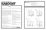
CHA-001
Brand: KABOOST Pages: 2

VE-150
Brand: ATEN Pages: 1

MyBlend PLUS
Brand: Oster Pages: 8

Space-Saving Blender
Brand: Hamilton Beach Pages: 24

50224
Brand: HAMILTON BEACH/PROCTOR SILEX Pages: 4

TPUH421
Brand: PTN Pages: 16

TRF-UZ1
Brand: Universal Remote Control Pages: 16

Optima Magnum 6
Brand: Taurus Pages: 56

HB-01
Brand: DS Produkte Pages: 28


