background image

                                 
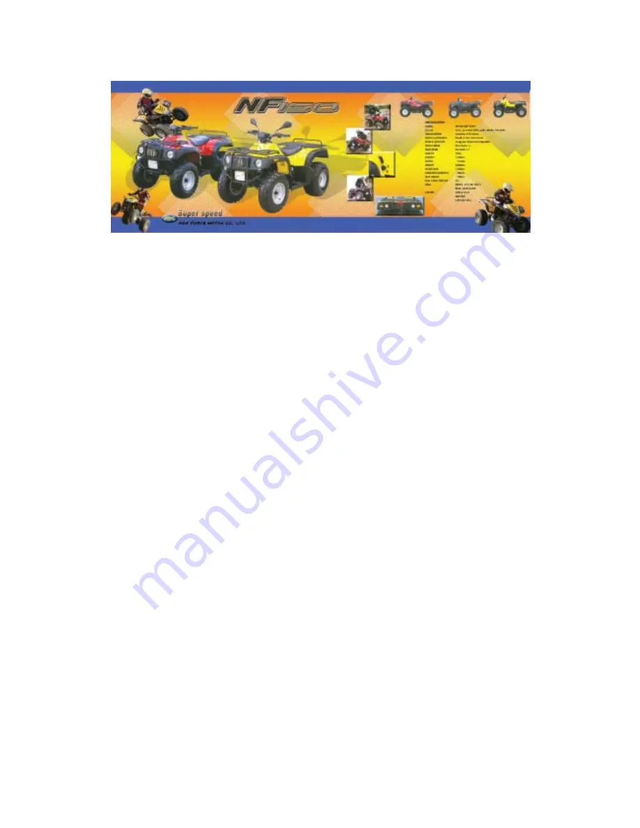
                            NF150- 150cc Utility Repair Manual 


CONTENTS 

 
1. INFORMTION                                                                                            2 
 
2. MAINTENANCE                                                                                        6 
 
3. ENGINE REMOVAL AND INSTALLATION                     12 
 
4. ENGINE FUEL SYSTEM                                                                          13 
 
5. ENGINE LUBRICATION AND COOLING SYSTEM              15 
 
6. 

ENGINE 

COMBUSTION 

SYSTEM 


      16 

 
7. TRANSMISSION SYSTEM     


25 

 
8. 

FRONT 

WHEEL 

AND 

STEERING 

SYSTEM 


    30 

 
9. REAR WHEEL SYSTEM   


38 

 
10. 

BODY 

COVER 

AND 

EXHAUST 

PIPE 

      41 

 
11. 

ELECTRICAL 

SYSTEM 

         43 

 
12. 

TROUBLE 

SHOOTING 

         47 


Summary of Contents for NF150

Page 1: ...OVAL AND INSTALLATION 12 4 ENGINE FUEL SYSTEM 13 5 ENGINE LUBRICATION AND COOLING SYSTEM 15 6 ENGINE COMBUSTION SYSTEM 16 7 TRANSMISSION SYSTEM 25 8 FRONT WHEEL AND STEERING SYSTEM 30 9 REAR WHEEL SYSTEM 38 10 BODY COVER AND EXHAUST PIPE 41 11 ELECTRICAL SYSTEM 43 12 TROUBLE SHOOTING 47 ...

Page 2: ...lfuric acid Protect your eyes skin and clothing If you contact it flush thoroughly with water and call a doctor if electrolyte gets In your eyes 1 2NOTES All information illustrations directions and specifications included in this publication are base on the latest product information available at the time of approval for printing NEW FORCE MOTOR CO LTD reserves the right to make changes at any ti...

Page 3: ...ic C V T V belt and Reverse CHASSIS Overall Length 1720mm Overall Width 920mm Overall Height 1030mm Seat Height 790mm Wheel base 1130mm Ground Clearance 220mm Dry Weight 182kg Fuel Tank Capacity 11 liter SUSPENSION Front Double A arm Rear Swing arm BRAKES Front Drum x 2 EEC SPEC ADDITION Rear Disk x 1 FOOT BRAKE SYSTEM TIRIES Front USA 22 7 10 EEC 21 7 10 Rear SPEC 22 10 10 EEC 21 10 8 ARTILLERY G...

Page 4: ...4 1 4 SERIAL NUMBER The frame serial number is stamped on the front of the frame The engine serial number is stamped on the left side of the crankcase ...

Page 5: ...ut 4 0kgm A arm bolt 4 0kgm A arm holder bolt 6 0kgm Front wheel nut 4 5kgm Disk holder bolt 5 5kgm Driven sprocket holder bolt 4 0kgm Drive chain sprocket nut 11 0kgm Rear axle and tire castle nut 11 0kgm Rear wheel bolt 4 5kgm Exhaust muffler mounting bolt 1 2kgm Engine fr hanger bolt 5 0kgm Engine rr hanger bolt 5 0kgm R L knuckle and tire castle nut 11 0kgm Swing arm axle nut 11 0kgm RR axle h...

Page 6: ...EERING STEM ROD NUT 4 Okgm ENGINE OIL JASO FC Grade or same degree oil GEAR LUBRICATION OIL SAE 30 900cc MISSIONOIL SAE9O 200cc 2 2 MAINTENANCE SCHEDULE The maintenance intervals in the follow table is based upon average riding conditions Riding in unusually dusty areas require more frequent servicing INITIAL SERVICE First week REGULAR SERVICE Every 30 operation days EVERY YEAR FUEL LINE HROTTLE O...

Page 7: ...rcially lubricant to prevent premature wear 2 5 THROTTLE CABLE ADJUSTMENT Slide the rubber cap of the adjuster off the throttle Housing loosen the lock nut and adjust the free play of the throttle lever turning the adjuster on the throttle housing Inspect the free play of the throttle lever 2 6 AIR CLEANER Unscrew the air cleaner cover screws Pull out the air filter element from the air cleaner ca...

Page 8: ...spark plug with 1 2kgm 2 8 IDLE RPM Connect a engine speed meter Warm up the engine 10 minutes are enough Turn the idle speed adjust screw on the carburetor to obtain the idle speed Turn in clockwise will get higher speed Turn out counter clockwise will get lower speed IDLE RPM 1550 士 50rpm 2 9 DRIVE CHAIN When the drive chain becomes very dirty it should be removed cleaned and lubricated by speci...

Page 9: ...er and cable for excessive play or other damage Replace or repair if necessary Measure the free play of the brake lever at the end of the brake lever The standard of free play is 15 25mm Inspect the rear brake lever and cable for excessive play or other damage Replace or repair if necessary Measure the free play of the rear brake lever at the end of the lever The standard is 15 25mm ...

Page 10: ...is excessive play inspect the steering stern rod 2 13 TOE IN Let the vehicle on level ground and the front wheels facing straight ahead Mark the centers of the tires to indicate the axle center height Measure the distance between the marks 750 10mm Carefully move the vehicle back let the wheels have turned 1800 so the marks on the tires are aligned with the axle center height Measure the distance ...

Page 11: ... the lock nuts torque 4 Okgrn 2 14 GEAR OIL Gear oil needs to be changed every 30 operating day There is a gear oil release bolt at the rear of engine Unscrew this release bolt and can let the dirty oil flow out STEP 1 The re add oil hole is on the engine case beside crank case and tinder crank case STEP 2 Re install the oil filler cap STEP 3 ...

Page 12: ... Disconnect the carburetor cable by unscrew wire on the carburetor Disconnect the wire connectors There are three connectors for carburetor auto choke starter motor and generator respectively Remove the drive chain retaining clip and master link and remove the drive chain Remove the engine hanger bolt on the engine 3 3 ENGINE INSTALLATION Engine installation is essentially the reverse order of rem...

Page 13: ...N FUEL AIR MIXTURE RATIO NO GOOD AIR CLEANER DIRTY INSULATOR LEAKS BROKE FUELTANK CAP BREATHING HOLE CLOGGED AUTO CHOKE ELECERICS SHORT CIRCUIT LEAN MIXTURE FUELJET OF CARBURETOR CLOGGED FUEL TANK CAP BREATHING HOLE CLOGG ED FUEL FILTER CLOGGED FUEL FLOWS IN THE TUBE UNSMOOTHLY FLOAT LEVEL IN CARBURETOR TOO LOW RICH MIXTURE FLOAT NEEDLE VALVE IN CARBURETOR FAULTY FLOAT LEVEL TOO HIGH AIR DUCT IN C...

Page 14: ...ASSY TUBE BAND REMOVE THE CARBURETOR AUTO CHOKE OPERATIONAL INSPECTION CHECK THETWO RESISTANTS OF AUTO CHOKE STANDARD BELOW 5Ω ENGINE STOPPED FOR 10 MINUTES AND ABOVE ASSEMBLY INSTALL THE CARB BY MATCHING ITS RAISED PART WITH THE INLET PIPE CAP TIGHTEN BOTH THE BANDS OF INLET PIPE AND A C AS SY TUBE INSTALL THE THROTTLE WIRE ON THE ROLLER INSTALL THE NEGATIVE FUEL TUBE AND THE FUEL TUBE CONNECT AU...

Page 15: ...en cannot work again When this engine is serious scratched you need to change the piston piston rings and cylinder together Also you need to check the combustion system and lubrication system carefully 5 3 OIL PUMP The quantity of oil that delivers out from oil pump which will be increased by the engine speed 5 4 COOLING SYSTEM The air is sucked by the engine cooling fan The cooling fan is on the ...

Page 16: ...D UPON PISTON HEAD OR IN COMBUSTION CHAMBER EXCESSIVE NOISE PISTON AND CYLINDER WORN OUT EXCESSIVE CARBON BUILD UP EXCESS SMOKE CYLINDER OR PISTON RINGS WORN OUT IMPROPER INSTALLATION OF PISTON RINGS PISTON OR CYLINDER WALL SCORED OR SCRATCHED OVERHEATING EXCESSIVE CARBON BUILD UPON THE PISTON OR COMBUSTION CHAMBER ENGINE COOLING SYSTEM FAN CYLINDER COVER WORKS BADLY OIL SUPPLY IS OUT OF ORDER WRO...

Page 17: ...COVER UNSCREW CAM CHAIN TENSIONER SCREW AND TAKE OFF O RING TIGHTEN THE CAM CHAIN TENSIONER SCREW IN A CLOCKWISE DIRECTION UNSCREW THE TWO BOLTS WHICH FIX THE CYLN HEAD REMOVE CAM SHAFT HOLDER NUT WASHER THEN THE CAM SHAFT CAN BE REMOVE MEASURE CAM SHAFT HIGH ANGLE SERVICE LIMIT IN 26 23mm EX 26 12mm ...

Page 18: ...STOPER PLATE AND ROCKER ARM MEASURE THE ACTION OUTER DIAMETERS OF ROCKER ARM SHAFT AND HOLDER SERVICE LIMIT 10 10mm ABOVE HOLDER MEASURE THE ACTION OUTER DIAMETERS OF ROCKER ARM SHAFT AND ROCKER ARM SERVICE LIMIT 9 9 mm SHAFT 10 10mm ROCKER ARM REMOVE CYLN HEAD REMOVE SHROUD A B INLET PIPE AND HEAD COVER REMOVE CAM HOLDER AND MUFFLER ...

Page 19: ...MBLY CYLN HEAD REMOVE RETAINER VALVE SPG SPG SEAT VALVE STEM SEAL CLEAR THE COM BUST1ON CARBON ATTENTION DO NOT HARM THE CYLN HEAD INSTALLATION SURFACE MEASURE THE INNER OUTER VALVE SPG FREE LENGTH SERVICE LIMIT INNER 31 2 mm MIN OUTER34 1 mm M1N CHECK IF VALVE GUIDE BENT BURNED VALVEAND GUIDE OPERATE SMOOTHLY VALVE OUTER DIAMETER MEASURETHE VALVE OUTER DIAMETER SERVICE LIMIT 4 9mm MIN ...

Page 20: ...LDER ASSEMBLY THE CAM HOLDER MATCH THE EX MARK ON CAM HOLDER WITH THE EX VALVE TURN THE T MARK OF FLY WHEEL TO MATCH WITH R COVER INDICATOR POINT PLACE THE CAM SPKT HOLE FACES ABOVE OF CYLN HEADTHE TWO DENTED PUCH POINTS ARE PARALLEL WITH THE CYLN HEAD INSTALLATION SURFACE INSTALL THE CAM SHAFT ON THE CYLN HEAD INSTALL THE CAM CHAIN ON THE SPKT ...

Page 21: ...YLN HEAD NUT TORQUE 2 Okgm LOOSEN THE ADJUST SCREN OF CAM CHAIN IN AANTI CLOCKWISE DIRECTION ADJUSTMENT VALVE CLEARANCE VALVE CLEARANCE 0 07 0 02mm APPLY LUBRICANT ON THE SURFACE OF NEW O RING TIGHTEN NHEAD COVER BOLT ...

Page 22: ...LEAR THE LEFT OVER ON CYLN SURFACE REMOVE PISTON REMOVE PISTON PIN CLIP ATTENTION DO NOT DROPTHE CLIP INTO THE CRANK CASE MEASURE PISTON AND PISTON RING CLEARANCE SERVICE LIMIT TOP RING 0 09mm max SECOND RING 0 09mm max MEASURE THE PISTON RING GAP BY PUTTING THE PISTON RING AT THE CYLN SKIRT SERVICE LIMIT 0 5mm max ...

Page 23: ...OUTER DIAMETER SERVICE LIMIT 56 9mm min PISTON AND PIN CLEARANCE SERVICE LIMIT 0 02mm max MEASURETHECYLN INNER DIAMETER SERVICE LIMIT 57 1mm max PISTON AND CYLN CLEARANCE SERVICE LIMIT 0 1mm max MEASURE CYLN INSTALLATION SURFACE SERVICE LIMIT 0 05mm max MEASURE I HE CRANK SHAFT CON ROD SMALL HOLE INNER DIAMETER SERVICE LIMIT 15 06mm max ...

Page 24: ...ELY AFTER INSTALLATION INSTALL THE PISTON AND CYLINDER CLEAR THE LEFT OVER ON CRANK CASE INSTALL PISTON PISTON PIN ATTENTION THERE IS A IN MARK ON TOP OF THE PISTON IT SHOULD BE PLACED AT INLET VALVE DO NOT DROPTHE CUP INTO THE CRAN CASE INSTALL THE DOWEL PIN AND GASKET ON CRANK CASE COMPRESS THE PISTON RING SET TO INSTALL INTO CYLN MAKE SURE THE RAISED PART OF THE CAM CHAIN GUIDE IS FIXED INTO CY...

Page 25: ...7 1 REMOVE DRIVE FACE ASSY REMOVE LCOVER DUCFTUBEAND LCOVER REMOVE DRIVE FACE TAKE OFF DRIVE BELT REMOVE THE DRIVE FACE ASSEMBLY INSPECF DRIVE BELT WIDTH SERVICE LIMIT 17 5mm min DISASSEMBLY THE RAMP PLATE TAKE OFF SIX ROLLERS ...

Page 26: ...E THE MOVABLE DRIVE FACE INNER DIAMETER SERVICE LIMIT 24 06 max INSPECT THE DRIVE FACE BOSS FOR DAMAGE OR WEAR MEASURE BOSS OUTER DIAMETER SERVICE LIMIT 23 94 mm min INSTALL ASSEMBLY MOVABLE DRIVE FACE AND ROLLER RAMP PLATE INSTALL DRIVE FACE INTO THE CRANK SHAFF TIGHTEN THE DRIVE FACE NUT TORQUE 5 5kgm ...

Page 27: ...TER MAXIMUM LIMIT 125 5mm INSPECT THE LINING FOR DAMAGE OR WEAR MEASURE THE DRIVEN FACE LINING THICKNESS THE MINIMUM LIMIT 1 5mm IFTHEY ARETHINNERTHAN THE MINIMUM LIMIT REPLACE THE DRIVEN FACE LININGS MEASURE THE MOVABLE DRIVEN FACE INNER DIAMETER SERVICE LIMIT 34 06mm max MEASURE THE MOVABLE DRIVEN FACE SPRING FREE LENGTH SERVICE LIMIT 130mm min ...

Page 28: ...DIAMETER SERVICE LIMIT 33 94mm min INSTALL THE MOVABLE DRIVEN FACE INTO THE DRIVEN FACE PUT IN 9 0 9 5g GREASE INTO THE HOLE OF DRIVEN FACE AFTER INSTALLATION THE SURFACE OF DRIVEN FACE SHOULD BE FREE FROM ANY GREASE INSTALLTHE CLUTOH OUTER THEN TIGHTEN DRIVEN FACE NUT TORQUE 5 5kgm ...

Page 29: ...and nuts fastened on the left side case of engine Take off the right side floor panel and the drive chain to get working space better 2 U S model Take off the Gear Shift Position Plate and its fastener European model Release the Foot Brakes Level and other mechanism surrounded to the gearbox if it is necessary ...

Page 30: ...n the vehicle over to the left side to get the engine slide out from its hanger and it is ready for the further work to the engine on the working table Release the gearbox cover by Hex Sock Bolt M8 70 1pc and M8 30 6pcs at torque of 3 2 Kg M 5 Release the Drive Sprocket 18T and Shifter Assembly by take away of the U Nut M16 and plain washer I D 16 5 mm x O D 24 mm x T 4 mm by the torque of 11 0 Kg...

Page 31: ...r Shift Spindle for sliding the Final shaft out from its location 7 Reverse the procedures to Pitt those parts back in after the repair jobs is completely done Make sure the correctness of the gear shifting sequence by manually turning the drive sprocket before drive chain has been put in place U S model Release the Flange Bolt M 6 x 12 2pcs and Nylon Nuts 6 mm of gear shift position plate and pos...

Page 32: ...ACE ASSY REMOVE RETURN SPRING KICK STARF SPINDLE AND STARTER IDLE GEAR INSTALL THE KICK START SPINDLE APPLY SOME GREASE AT THE PART OF KICK SPINDLE THAT PART IS TO BE INSTALLED AT L CASE MATCH THE PIN OF IDLE GEAR WITH THE CRANK CASE IMPRESSION APPLY SOME GREASE ON THE IDLE GEAR ...

Page 33: ...CORRECT BRAKEADJUSTMENT STUCKED BRAKE CABLE STEERS TO ONE SIDE BENT STEERING STEM ROD WHEEL INSTALLED INCORRECTLY UNEQUAL TIRE PRESSURE BENT FRAME POOR BRAKE PERFORMANCE BRAKE SHOES WORN WORN BRAKE DRUM BRAKE LININGS OILY GREASY OR DIRTY IMPROPER BRAKE ADJUSTMENT FRONT SUSPENSION NOISE LOOSE FRONT SUSPENSION FASTENERS BINDING SUSPENSION LINK HARD SUSPENSION FAULTY FRONT AARM BUSHINGS IMPROPERLY IN...

Page 34: ...acket Remove the bolts attaching the speedometer Remove the handle bar holder and handle bar INSTALLATION Put the handlebar on the lower holders Make sure the handlebar punch mark with the top of the handlebar lower holders Install the handlebar upper holders with the L or R marks facing forward Tighten the forward bolts first then tighten the rear bolts Install the handlebar speedometer ...

Page 35: ...e Tighten the screw securely Aligning the split line of the throttle housing and holder with the punch mark Tighten the screw securely 8 3 FRONT WHEEL REMOVAL Raise the front wheels off the ground by placing a block under the frame Remove the front wheel nuts washer and wheels INSTALLATION Install and tighten the four wheel nuts Torque 4 5kgm Remember put a cotter pin in the castle nut ...

Page 36: ...e minimum limit 1 5mm If they are thinner than the minimum limit replace the brake linings Measure the brake drum inner diameter The maximum limit 111 mm Turn the inner race of each bearing with fingers The bearings should turn smoothly and quietly If the race does not turn smoothly or quietly remove and discard the bearings ...

Page 37: ... and nut Torque l 0kgm Install the brake panel on the knuckle Connect the brake cable to the brake arm Install the brake arm Tighten the screws securely Position the brake shoes in their original locations and install the brake shoe spring Install the brake drum and front wheel Install the castle nut and cotter pin 8 5 STEERING SYSTEM REMOVAL OF KNUCKLE AND STEERING STEM ROD Remove the front wheel...

Page 38: ...e or cracks STEERING SHAFT REMOVAL Remove the handle bar and speedometer Remove the front body cover Unscrew the steering shaft fixed out below shaft Pull steering shaft carefully HOLDER INSPECTION Remove the steering shaft Remove the holder from the shaft Inspect the holder for damage or wear replace if necessary Measure the holder inner diameter Maximum limit 32 2mm O RING INSPECTION Remove the ...

Page 39: ... bearing is on the front part of frame The bearing should turn smoothly and quietly Also check that the bearing outer race fits in the holder Replace the bearing if necessary INSTALLATION OF STEERING SHAFT Install the steering shaft with the holder Apply grease to the holder Install the steering shaft holder and tighten the bolt Torque 2 0kgm Install the steering shaft nut and tighten it This nut ...

Page 40: ...40 INSTALLATION OF STEERING STEM ROD Install left steering stem rod with L mark on the wheel side Install right steering stem rod with R mark on the steering shaft side ...

Page 41: ...KE Let the rear wheels off the ground Release the cotter pin axle nut and washer Release the wheel and hub Remove the brake disk protector Check the brake disk thickness The minimum limit is 3 0mm Check the brake disk for damage Replace if necessary Check the brake pad thickness not over wear indicate mark 9 3 DRIVE MECHANISM REMOVAL AND INSPECTION Remove the rear wheel Remove the drive chain prot...

Page 42: ...he driven sprocket Check the driven sprocket for damage or wear Let the rear axle lie in V blocks and check the run out The run out limit is 0 5mm Check the turning of rr axle holder bearing with fingers The bearings should turn smoothly and quietly Replace if necessary ...

Page 43: ... Install the drive chain protector Torque 4 0kgm 9 4 REAR BRAKE AND WHEEL INSTALLATION Install the brake caliper assy and disk DISK HOLDER TORQUE 5 5kgrn CALIPER TORQUE 3 2kgm INSTALL THE DISK PROTECTOR TIGHTEN THE RR AXLE HOLDER NUT WITH 25 0kgm Assembly the wheel and rr wheel hub Tighten the rear axle nut with 11 0kgrn Install a new cotter pin Tighten the rr wheel bolt with 4 5kgm Adjust chain s...

Page 44: ...ew the four bolts which fix the rear body cover on the fixed bar just above the i ear body cover Unscrew the six screws which connect with footrest plate So the rear body cover can be removed 10 2 FRONT BODY COVER REMOVE Remove the handle bar assembly and speedometer assembly Unscrew the two fixed screws above the front body cover Disconnect R L lever wire and switch wire and meter wire Remove bra...

Page 45: ...ust pipe bolts that fixed with engine Unscrew the two bolts which connect the FR PIPE and RR PIPE Unscrew the hammer bolt at the fix bar of rear body cover Remove the exhaust pipe carefully 10 4 EXHAUST PIPE INSTALLATION Installation is the reverse order of removal Torque Exhaust muffler bolts 1 2kgm After installation make sure that there is no exhaust leaks ...

Page 46: ...tor exciter coil Loosen contacted terminals Faulty ignition coil IGNITION SECONDARY CIRCUIT Faulty plug Loosen contacted spark plug wire IMPROPER IGNITION TIMING Faulty generator Faulty CDI unit CHARGING SYSTEM FAILURE LOOSE BROKEN OR SHORTED WIRE FAULTY ALTERNATOR FAULTY IGNITION SWITCH ENGINE INTERMITTENT POWER LOOSE BATTERY CONNECTION LOOSE CHARGING SYSTEM CONNECTION STARTER MOTOR WILL NOT TURN...

Page 47: ...d does not require adjustment 11 4 ALTERNATOR EXCITER COIL Disconnect the exciter coil wire Measure the resistance between the wire and ground STANDER GREEN Y ELLOW 40 300Ω 20ºC BLUE BLACK 300 lkΩ 20ºC 11 5 BATTERY CAUTION The battery gives off explosive gases keep sparks flames and cigarettes away Provide adequate ventilation when charging or using the battery in an open area The battery contains...

Page 48: ... BATTERY INSTALLATION Install the battery in the reverse order of removal After installing the battery coat the terminals with clean grease 11 7 CHARGING Connect the charge positive cable to the battery positive terminal Connect the charge negative cable to the battery negative terminal Using 0 9A charging current about 5 hours Normal charging Or using 4A charging current about 1 2 hour Quick char...

Page 49: ...49 11 8 WIRING DIAGRAMS ...

Page 50: ...HORFED IGNITION COIL BROKEN OR SHORFED SPARK PLUG WIRE FAULTY PULSE GENERATOR FAULTY IGNITION SWITCH TEST CYLINDER COMPRESSION N G WORN CYLINDER AND PISTON LOW COMPRESSION RINGS O K DAMAGED CYLINDER HEAD GASKEF ENGINE STARES BUT STOPS START THE ENGINE AUTO CHOKE OFF OR DAMAGED AUTO CHOKE POWER WIRE DISCONNECTED IMPROPERLY ADJUSTED AIR SCREW ENGINE DOES NOT FIRE IMPROPER INGITION TIMING FUEL AIR MI...

Page 51: ...DAIR SCREW O K CHECK FOR LEAKING N G DETERIORATED INSULATOR O RING INTAKE PIPE LOOSE CARBIJRETOR O K PERFORM SPARK TEST LOOSE OR DISCONNECTED IGNITION WEEK OR INTERMITTENT SPARK SYSTEM WIRES FAULTY CARBON OR WET FOULED SPARK PLUG FAULTY ALTERNATOR FAULTY C D I UNIT FAULTY IGNITION SWITCH FAULTY IGNITION COIL FAULTY PULSE GENERATOR BROKEN OR SHORFED SPARK PLUG WIRE FAULTY ENGINE STOP SWITCH ...

Page 52: ...ING N G FAULTY C D I UNIT FAULTY PULSE GENERATOR O K CHECK FUELTUBE AT FUEL FLOW RESTRICTED LACK OF FUEL IN TANK CARBURETOR CLOGGED RJEL LINE CLOGGED FUEL VALVE LOGGED FILJELTAANK BREATHER HOLE REMOVE CARBURETOR CLOGGED CLEAN WITH HIGH PRESSURE AIR GUN CHECK FOR CLOGGED JETS ...

Page 53: ...K CAP BREATHER HOLE CHECK IGNITION TIMING N G FAULTY PULSE GENERATOR FAULTY C D I UNIT O K TOO LOW TEST CYLINDER COMPRESSION LEAKING HEAD GASKET WORN CYLINDER AND PISTON O K RINGS CHECK CARBURETOR CLOGGED CLEAN O K FOULED OR DISCOLORED CHECK SPARK PLUG CLEAN THE SPARK PLUG SPARK PLUG IS INCORRECT HEAT RANCE O K CHECK FOR ENGIN OVERHEATING EXCESSIVE CARBON OVERHEATING DEPOSITED IN COMBUSTION CHAMBE...

Page 54: ... ONE WHEEL IS WOBBLING BENT RIM IMPROPERLY INSTALLED WHEEL HIJB EXCESSIVE WHEEL BEARING PLAY BENT SWINGARM BENT FRAME SWINGARM PIVOT BUSHING EXCESSIVELY WORN VEHICLE PULLS TO ONE SIDE BENT STEERING STEM ROD INCORRECT STEERING STEM ROD ADJUSTMENT REAR TIE AIR PRESSIRE INCORRECT IMPROPER WHEELALIGNMENT BENT FRAME ...

Reviews: