NetUP HDMI Encoder 8x, User Manual
The NetUP HDMI Encoder 8x is a high-quality streaming device that allows you to easily transmit HDMI video signals over IP networks. For a seamless user experience, we provide a comprehensive User Manual, available for free download from our website. Get the most out of your product by referring to our detailed manual.
Share
Download


Reviews:
No comments
Related manuals for HDMI Encoder 8x

DCC-E
Brand: Helvest Pages: 2

ENC120
Brand: Reach Pages: 13

SEU4
Brand: Dolby Laboratories Pages: 23

iSignager iS-1620
Brand: QNAP Pages: 9

6614
Brand: Davis Instruments Pages: 24

Video Sweep Generator MVG 10
Brand: Kathrein Pages: 28

MAXX SST VEC051D
Brand: Vector Pages: 44

LokPilot Fx micro V3.0
Brand: Esu Pages: 72

Sunny Boy 6000
Brand: SMA Pages: 90

HIT-3MF3HDMI-641RIPRO
Brand: C&C TECHNIC Pages: 55

HSU12VHJ(DB)
Brand: Haier Pages: 22

HSU12VHGDB-G
Brand: Haier Pages: 10

HSU12VHJ(DB)
Brand: Haier Pages: 115

HSU12VHG-B
Brand: Haier Pages: 98
10698
Brand: AEG Pages: 60
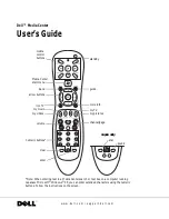
Media Center
Brand: Dell Pages: 24

FR-A800 Plus Series
Brand: Mitsubishi Electric Pages: 66

FR-A7NP
Brand: Mitsubishi Electric Pages: 90


