


Reviews:
No comments
Related manuals for Snakky 6-30R/I
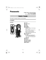
KX-TCD320FX
Brand: Panasonic Pages: 6

Solaris VISION BLSA3
Brand: Baby Lock Pages: 20

Reactor
Brand: Family Fun Companies Pages: 26

2-45DTM
Brand: Blastrac Pages: 59

Office ECoil46
Brand: Digital Finishing Group Pages: 6

52 i Series
Brand: Dürkopp Adler Pages: 84

ECO-C Binder 2:1 Pitch
Brand: Officezone Pages: 5

PT0502-GR
Brand: UnionSpecial Pages: 72

550-19-2
Brand: Duerkopp Adler Pages: 9

Pulsar E 300
Brand: Fellowes Pages: 54

52-56
Brand: Singer Pages: 67

HAZE950
Brand: AFXlight Pages: 20

TB 1280
Brand: Olympia Pages: 104

DDL-900A
Brand: JUKI Pages: 52

DLN-6390
Brand: JUKI Pages: 380

Voice Mail
Brand: Xblue Networks Pages: 24

Strings SS-30
Brand: Yamaha Pages: 7

DMM-2202DA
Brand: KANSAI SPECIAL Pages: 13


