JUKI DDL-900A, Instruction Manual
The JUKI DDL-900A is a high-performance sewing machine designed for professionals. To ensure user safety, it is important to follow the "Cautions For Safety" guidelines included in the user manual. Download the manual for free from manualshive.com to unleash the full potential of this remarkable product.
Share
Download


Reviews:
No comments
Related manuals for DDL-900A
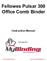
Pulsar E 300
Brand: Fellowes Pages: 7
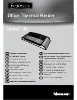
Helios 30
Brand: Fellowes Pages: 8
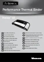
Helios 60
Brand: Fellowes Pages: 8

1243-712/02
Brand: Pfaff Pages: 56
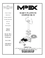
MARCY PLATINUM MS-91
Brand: MPEX Pages: 11

Autopax PAX600H
Brand: Quasar Pages: 148

95K32
Brand: Singer Pages: 9

BLMY
Brand: Baby Lock Pages: 226

CLP12IA
Brand: Clipper Pages: 42

CombBind C110E
Brand: GBC Pages: 74

MEMORYCRAFT 300E
Brand: Janome Pages: 48

Bourg Binder 3001
Brand: C.P.Bourg Pages: 51

H5 Hazer
Brand: Mega Pages: 10

H-Type 969
Brand: DURKOPP ADLER Pages: 90

Smoke 400v3
Brand: Nebula Pages: 8

CP-170
Brand: JUKI Pages: 34

DDL-8700A-7
Brand: JUKI Pages: 60

HZL-27Z
Brand: JUKI Pages: 24


